- Table of Contents
-
- H3C CR16000-F Router Series Installation Guide-5W107
- 00-Preface
- 01-Chapter 1 Preparing for Installation
- 02-Chapter 2 Installing the Router
- 03-Chapter 3 Installing FRUs
- 04-Chapter 4 Connecting Your Router to the Network
- 05-Chapter 5 Troubleshooting
- 06-Chapter 6 Replacement Procedures
- 07-Appendix A Engineering Labels for Cables and Devices
- 08-Appendix B Cabling Recommendations
- 09-Appendix C Repackaging the Router
- Related Documents
-
| Title | Size | Download |
|---|---|---|
| 01-Chapter 1 Preparing for Installation | 3.94 MB |
Preparing for installation
This section describes preparations for installing a CR16000-F router.
Safety recommendations
To avoid possible bodily injury and equipment damage, read all safety recommendations carefully before installation. Note that the recommendations do not cover every possible hazardous condition.
General safety recommendations
· Keep the chassis clean and dust-free.
· Do not place the router on a moist area, and avoid liquid flowing into the router.
· Make sure the ground is dry and flat and anti-slip measures are in place.
· Keep the chassis and installation tools away from walk areas.
· Do not wear loose clothing, jewelry (for example, necklace) or any other things that could get caught in the chassis when you install and maintain the router.
Electricity safety
· Clear the work area of possible electricity hazards, such as ungrounded power extension cables, missing safety grounds, and wet floors.
· Locate the emergency power-off switch in the room before installation so you can quickly shut power off when an electrical accident occurs.
· Remove all external cables, including power cords, before moving the chassis.
· Do not work alone when the router has power.
· Never assume that power has been disconnected from a circuit. Always check.
Moving safety
|
|
WARNING! · Hold the chassis handles firmly to move the router. · Do not hold the handle of a fan tray or power supply, air vents, or the handle on the real panel to move the router. Doing so might cause equipment damage or even bodily injury. |
The router is heavy and large. When you move the router, follow these guidelines:
· Remove all external cables (including power cords), cards, fan trays, and power supplies before moving the chassis.
· Moving the chassis requires a minimum of two people, and you can use a mechanical lift as needed.
· Lift and put down the chassis slowly and never move suddenly.
ESD prevention
To prevent the electric component from being damaged by electrostatic discharge (ESD), follow these guidelines:
· Ground the router correctly. For how to ground your router, see "Grounding the router."
· Always wear an ESD wrist strap and make sure it is correctly grounded when installing FRUs. For how to use an ESD wrist strap, see "Attaching an ESD wrist strap."
· Hold a PCB by its edges. Do not touch any electronic components or printed circuit.
· Put cards away in ESD bags for future use.
Laser safety
|
|
WARNING! Disconnected optical fibers or transceiver modules might emit invisible laser light. Do not stare into beams or view directly with optical instruments when the router is operating. |
Examining the installation site
The router must be used indoors. To ensure correct operation and long service life of your router, the installation site must meet the requirements in this section.
Weight support
Make sure the floor can support the total weight of the rack, chassis, cards, power supplies, and all other components. Additionally, the floor loading plan must also consider system expansion, such as adding more cards. For more information, see H3C CR16000-F Router Series Hardware Information and Specifications.
Temperature
|
CAUTION: If condensation appears on the chassis when you move it to a high-temperature environment, dry the chassis before powering it on to avoid short circuits. |
To ensure correct operation of the router, make sure the room temperature meets the requirements in Table 1.
Table 1 Temperature requirements
|
Temperature |
Range |
|
Operating temperature |
0°C to 45°C (32°F to 113°F) |
|
Storage temperature |
–40°C to +70°C (–40°F to +158°F) |
Humidity
Maintain appropriate humidity in your equipment room, as described in Table 2.
· Lasting high relative humidity can cause poor insulation, electricity leakage, mechanical property change of materials, and metal corrosion.
· Lasting low relative humidity can cause washer contraction and ESD and cause problems including loose mounting screws and circuit failure.
|
Humidity |
Range |
|
Operating humidity |
10% RH to 95% RH, noncondensing |
|
Storage humidity |
5% RH to 95% RH, noncondensing |
Cleanliness
Dust buildup on the chassis might result in electrostatic adsorption, which causes poor contact of metal components and contact points. In the worst case, electrostatic adsorption can cause communication failure.
Table 3 Dust concentration limits in the equipment room
|
Substance |
Particle diameter |
Concentration limit |
|
Dust particles |
≥ 0.5 µm |
≤ 1.8 × 10⁷ particles/m3 |
Corrosive gases can accelerate corrosion and aging of components. Make sure the corrosive gases in the equipment room do not exceed the concentration limits as shown in Table 4.
Table 4 Corrosive gas concentration limits in the equipment room
|
Gas |
Average concentration (mg/m3) |
Maximum concentration (mg/m3) |
|
SO2 |
0.3 |
1.0 |
|
H2S |
0.1 |
0.5 |
|
Cl2 |
0.1 |
0.3 |
|
HCI |
0.1 |
0.5 |
|
HF |
0.01 |
0.03 |
|
NH3 |
1.0 |
3.0 |
|
O3 |
0.05 |
0.1 |
|
NOX |
0.5 |
1.0 |
EMI
All electromagnetic interference (EMI) sources, from outside or inside of the router and application system, adversely affect the router in the following ways:
· A conduction pattern of capacitance coupling.
· Inductance coupling.
· Electromagnetic wave radiation.
· Common impedance (including the grounding system) coupling.
To prevent EMI, use the following guidelines:
· If AC power is used, use a single-phase three-wire power receptacle with protection earth (PE) to filter interference from the power grid.
· Keep the router far away from radio transmitting stations, radar stations, and high-frequency devices.
· Use electromagnetic shielding, for example, shielded interface cables, when necessary.
· To prevent signal ports from getting damaged by overvoltage or overcurrent caused by lightning strikes, route interface cables only indoors.
Grounding
Using a good grounding system to protect your router against lightning shocks, interferences, and ESD is essential to the operating reliability of your router. For more information about grounding the router, see "Grounding the router."
Make sure the resistance between the chassis and the ground is less than 1 ohm.
Power
Perform the following tasks to meet the power requirements:
1. Calculate the system power consumption.
The system power consumption varies by card type and density. For more information about system power consumption calculation, see H3C CR16000-F Router Series Hardware Information and Specifications.
2. Select power supplies and identity the number of power supplies.
The total maximum output power of all power supplies must be higher than the system power consumption. For more information about available power supplies, see H3C CR16000-F Router Series Hardware Information and Specifications.
3. Verify that the power system at the installation site meets the requirements of the power supplies, including the input method and rated input voltage.
Cooling
For heat dissipation, make sure the following requirements are met:
· A minimum clearance of 10 cm (3.94 in) is reserved around the inlet and outlet air vents.
· The rack for the router has a good cooling system.
· The installation site has a good cooling system.
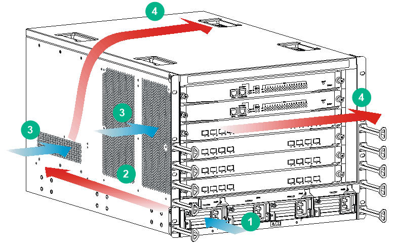
Figure 1 describes the airflow through the CR16010-F chassis. Figure 2 describes the airflow through the CR16010H-F chassis and CR16010H-FA chassis. Figure 3 describes the airflow through the CR16018-F chassis and CR16018-FA chassis. Figure 4 describes the airflow through the CR16005E-F chassis. Figure 5 describes the airflow through the CR16010E-F chassis. Figure 6 describes the airflow through the other models.
Figure 1 Airflow through the CR16010-F chassis
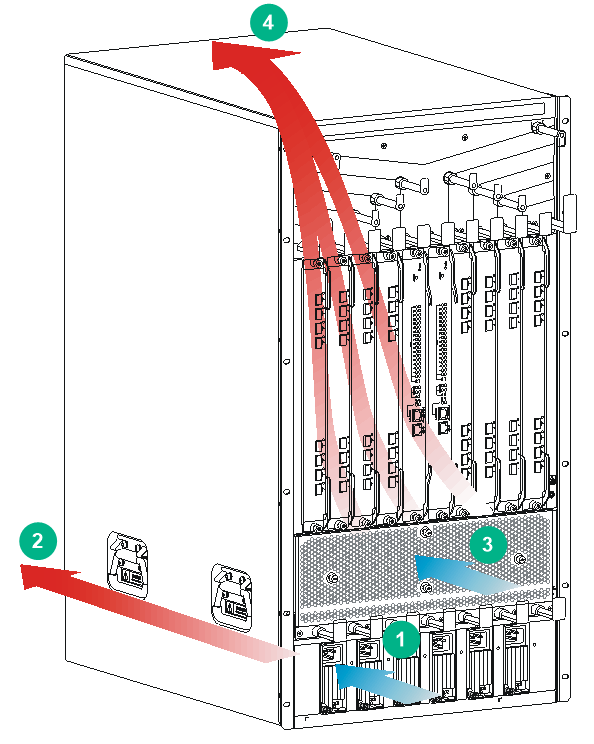
|
(1) Direction of the airflow into the power supplies |
(2) Direction of the airflow out of the power supplies |
|
(3) Direction of the airflow into the chassis |
(4) Direction of the airflow out of the chassis |
Figure 2 Airflow through the CR16010H-F chassis and CR16010H-FA chassis
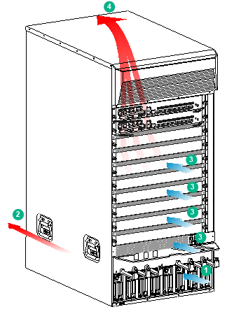
|
(1) Direction of the airflow into the power supplies |
(2) Direction of the airflow out of the power supplies |
|
(3) Direction of the airflow into the chassis |
(4) Direction of the airflow out of the chassis |
Figure 3 Airflow through the CR16018-F chassis and CR16018-FA chassis
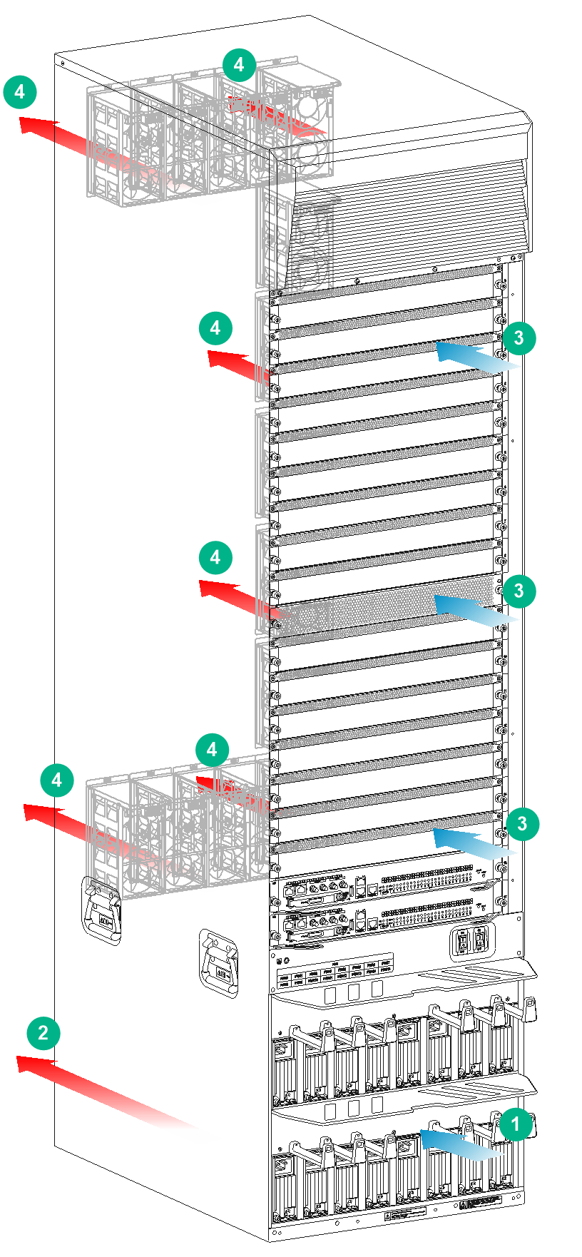
|
(1) Direction of the airflow into the power supplies |
(2) Direction of the airflow out of the power supplies |
|
(3) Direction of the airflow into the chassis |
(4) Direction of the airflow out of the chassis |
Figure 4 Airflow through the CR16005E-F chassis
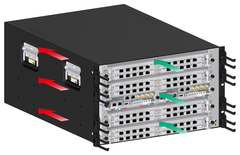
Figure 5 Airflow through the CR16010E-F chassis
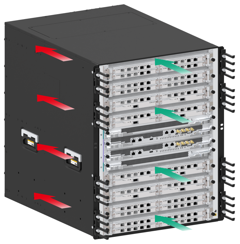
Figure 6 Airflow through the other models
|
(1) Direction of the airflow into the power supplies |
(2) Direction of the airflow out of the power supplies |
|
(3) Direction of the airflow into the chassis |
(4) Direction of the airflow out of the chassis |
Space
For easy installation and maintenance, follow these space requirements:
· Reserve a minimum clearance of 1 m (3.28 ft) between the rack and walls or other devices.
· For heat dissipation, make sure the headroom in the equipment room is not less than 3 m (9.84 ft).
· Make sure the rack has enough space to accommodate the router. See Table 5 for rack requirements. For more information about chassis dimensions, see H3C CR16000-F Router Series Hardware Information and Specifications.
Table 5 Router depth and rack requirements
|
Model |
Chassis depth |
Rack requirements |
|
CR16006-F |
Total depth: 772 mm (30.39 in) · 91 mm (3.58 in) from the mounting surface of the mounting brackets to the front end of the cable management brackets · 681 mm (26.81 in) from the mounting surface of the mounting brackets to the ejector levers of the switching fabric modules |
· A minimum of 94 mm (3.70 in) between the front rack posts and the interior side of the front door (including the door lock and handle). · A minimum of 684 mm (26.93 in) between the front rack posts and the interior side of the rear door (including the door lock and handle). If the rack meets these requirements and has a minimum depth of 0.8 m (2.62 ft), you can mount the router in the rack. As a best practice, use a rack with a minimum depth of 1.0 m (3.28 ft). |
|
CR16010-F (one fan tray) |
Total depth: 756 mm (29.76 in) · 75 mm (2.95 in) from the mounting surface of the mounting brackets to the front end of the cable management brackets · 681 mm (26.81 in) from the mounting surface of the mounting brackets to the ejector levers of the switching fabric modules |
· A minimum of 78 mm (3.07 in) between the front rack posts and the interior side of the front door (including the door lock and handle). · A minimum of 684 mm (26.93 in) between the front rack posts and the interior side of the rear door (including the door lock and handle). If the rack meets these requirements and has a minimum depth of 0.8 m (2.62 ft), you can mount the router in the rack. As a best practice, use a rack with a minimum depth of 1.0 m (3.28 ft). |
|
CR16010-F (two fan trays) |
Total depth: 759 mm (29.88 in) · 78 mm (3.07 in) from the mounting surface of the mounting brackets to the front end of the cable management brackets · 681 mm (26.81 in) from the mounting surface of the mounting brackets to the ejector levers of the switching fabric modules |
· A minimum of 81 mm (3.19 in) between the front rack posts and the interior side of the front door (including the door lock and handle). · A minimum of 684 mm (26.93 in) between the front rack posts and the interior side of the rear door (including the door lock and handle). If the rack meets these requirements and has a minimum depth of 0.8 m (2.62 ft), you can mount the router in the rack. As a best practice, use a rack with a minimum depth of 1.0 m (3.28 ft). |
|
CR16014-F |
Total depth: 756 mm (29.76 in) · 95 mm (3.74 in) from the mounting surface of the mounting brackets to the front end of the cable management brackets · 661 mm (26.02 in) from the mounting surface of the mounting brackets to the ejector levers of the switching fabric modules |
· A minimum of 98 mm (3.86 in) between the front rack posts and the interior side of the front door (including the door lock and handle). · A minimum of 664 mm (26.14 in) between the front rack posts and the interior side of the rear door (including the door lock and handle). If the rack meets these requirements and has a minimum depth of 0.8 m (2.62 ft), you can mount the router in the rack. As a best practice, use a rack with a minimum depth of 1.0 m (3.28 ft). |
|
CR16010H-F/CR16010H-FA |
Total depth: 777 mm (30.59 in) · 114 mm (4.49 in) from the mounting surface of the mounting brackets to the front end of the cable management brackets · 663 mm (26.10 in) from the mounting surface of the mounting brackets to the chassis rear handles |
· A minimum of 117 mm (4.61 in) between the front rack posts and the interior side of the front door (including the door lock and handle). · A minimum of 666 mm (26.22 in) between the front rack posts and the interior side of the rear door (including the door lock and handle). If the rack meets these requirements and has a minimum depth of 0.8 m (2.62 ft), you can mount the router in the rack. As a best practice, use a single-door rack with a minimum depth of 1.0 m (3.28 ft). |
|
CR16018-F/CR16018-FA |
Total depth: 777 mm (30.59 in) · 114 mm (4.49 in) from the mounting surface of the mounting brackets to the front end of the cable management brackets · 663 mm (26.10 in) from the mounting surface of the mounting brackets to the chassis rear handles |
· A minimum of 117 mm (4.61 in) between the front rack posts and the interior side of the front door (including the door lock and handle). · A minimum of 666 mm (26.22 in) between the front rack posts and the interior side of the rear door (including the door lock and handle). If the rack meets these requirements and has a minimum depth of 0.8 m (2.62 ft), you can mount the router in the rack. As a best practice, use a single-door rack with a minimum depth of 1.0 m (3.28 ft). |
|
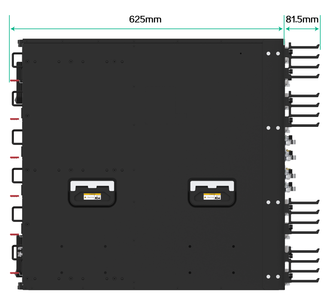
CR16005E-F/CR16010E-F |
Total depth: 706.5 mm (27.82 in) · 81.5 mm (3.21 in) from the mounting surface of the mounting brackets to the front end of the cable management brackets · 625 mm (24.61 in) from the mounting surface of the mounting brackets to the latch on the power supply |
· A minimum depth of 0.8 m (2.62 ft) · A minimum of 84.5 mm (3.33 in) between the front rack posts and the interior side of the front door (including the door lock and handle). · A minimum of 628 mm (24.72 in) between the front rack posts and the interior side of the rear door (including the door lock and handle). |
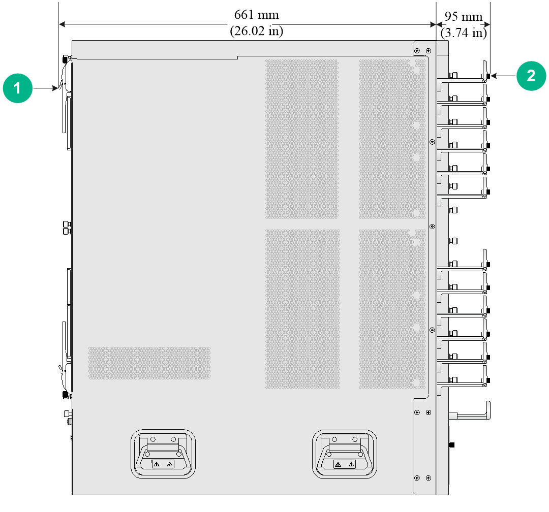
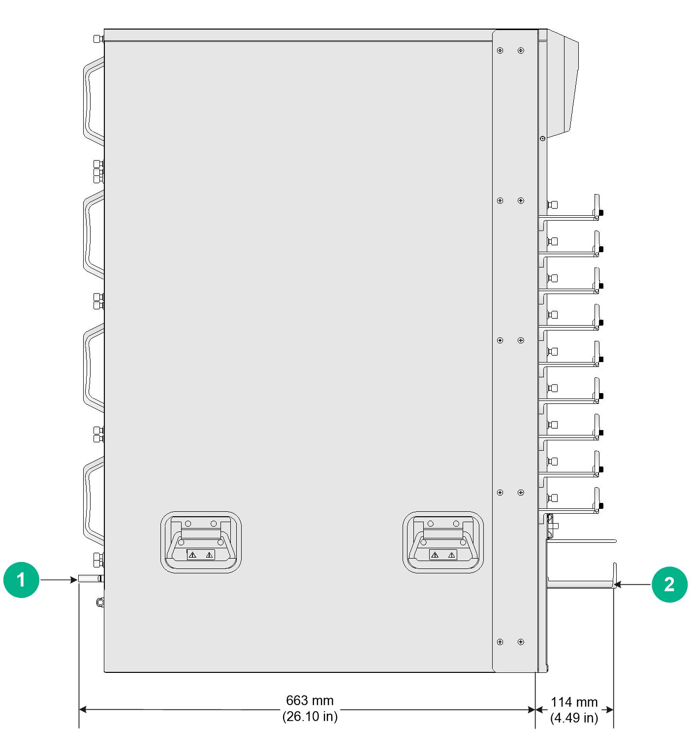
Figure 7 describes the depth of the CR16006-F, CR16010-F (one fan tray), CR16010-F (two fan trays), and CR16014-F chassis. Figure 8 describes the depth of the CR16010H-F, CR16010H-FA, CR16018-FA, and CR16018-F chassis. Figure 9 describes the depth of the CR16005E-F and CR16010E-F chassis.
Figure 7 CR16014-F chassis depth
|
(1) Ejector levers of the switching fabric modules |
(2) Cable management bracket |
Figure 8 CR16010H-F chassis depth
|
(1) Handle at the rear of the chassis |
(2) Cable management bracket |
Figure 9 CR16010E-F chassis depth
|
|
NOTE: · If the rack does not meet the requirements described in Table 5, the rack door might fail to be closed after you install the router of standard configurations in the rack. · The signal cables and power cords are routed through the front of the chassis. If you use power cords that has a conductor cross-section area of a minimum of 16 sq mm (0.02 sq in), leave more space between the front rack posts and the front door as appropriate. |
Tools and equipment
No installation tools and equipment are provided with the router. Prepare installation tools and equipment yourself as required. Table 6 lists the tools and equipment that you might use during installation.
Table 6 Tools and equipment list
|
Category |
Tool |
|
Measuring and marking tools |
Long tape Ruler (1 meter, or 3.28 ft) Gradienter Marker Chalk line Pencil |
|
Drills |
Percussion drill Electric drill Several auxiliary drill bits |
|
Fastening tools |
Flat-blade screwdriver P4-75 mm Phillips screwdriver P1-100 mm, P2-150 mm, and P3-250 mm Socket wrench M5 Socket wrench M6 Box-end wrench |
|
Small tools |
Needle-nose pliers Diagonal pliers Combination pliers Wire-stripping pliers Crimping pliers RJ-45 crimping pliers File Handsaw |
|
Auxiliary tools |
ESD wrist strap Hair brush Paper knife Hand bellows Electric iron Solder wire Ladder Cable stripper Vacuum cleaner Crowbar Rubber hammer |
|
Tools for fiber-optic cleaning |
Lint-free paper Optical fiber microscope |
|
Equipment |
Multimeter 500 V Megohmmeter for measuring the insulation resistance Error detector Optical power meter Earth resistance tester |
