- Table of Contents
-
- 06-Layer 3—IP Routing Configuration Guide
- 00-Preface
- 01-Basic IP routing configuration
- 02-Static routing configuration
- 03-RIP configuration
- 04-OSPF configuration
- 05-IS-IS configuration
- 06-Basic BGP configuration
- 07-Advanced BGP configuration
- 08-Policy-based routing configuration
- 09-IPv6 static routing configuration
- 10-RIPng configuration
- 11-OSPFv3 configuration
- 12-IPv6 policy-based routing configuration
- 13-Routing policy configuration
- 14-DCN configuration
- Related Documents
-
| Title | Size | Download |
|---|---|---|
| 08-Policy-based routing configuration | 175.82 KB |
Contents
Restrictions and guidelines: PBR configuration
Setting match criteria for a node
Configuring actions for a node
Specifying a policy for local PBR
Specifying a policy for interface PBR
Enabling the PBR logging feature
Verifying PBR policy configuration
Displaying PBR configuration and statistics
Example: Configuring packet type-based local PBR
Configuring PBR
About PBR
Policy-based routing (PBR) uses user-defined policies to route packets. A policy can specify parameters for packets that match specific criteria such as ACLs. The parameters include the next hop, output interface, default next hop, SRv6 TE policy, SR-MPLS TE policy, default SRv6 TE policy, default SR-MPLS TE policy, and default output interface.
Packet forwarding process
When the device receives a packet, the device searches the PBR policy for a matching node to forward that packet.
· If a matching node is found and its match mode is permit, the device performs the following operations:
a. Uses the next hops, output interfaces, SRv6 TE policies, or SR-MPLS TE policies specified on the node to forward the packet.
b. Searches the routing table for a route (except the default route) to forward the packet if one of the following conditions exists:
- No next hops, output interfaces, SRv6 TE policies, or SR-MPLS TE policies are specified on the node.
- Forwarding failed based on the next hops, output interfaces, SRv6 TE policies, or SR-MPLS TE policies.
c. Uses the default next hops, default output interfaces, default SRv6 TE policies, or default SR-MPLS TE policies specified on the node to forward the packet if one of the following conditions exists:
- No matching route was found in the routing table.
- The routing table-based forwarding failed.
d. Uses the default route to forward the packet if one of the following conditions exists:
- No default next hops, default output interfaces, default SRv6 TE policies, or default SR-MPLS TE policies are specified on the node.
- The forwarding failed based on the default next hops, default output interfaces, default SRv6 TE policies, or default SR-MPLS TE policies.
· The device performs routing table lookup to forward the packet in either of the following conditions:
¡ No matching node is found.
¡ A matching node is found, but its match mode is deny.
PBR types
PBR includes the following types:
· Local PBR—Guides the forwarding of locally generated packets, such as ICMP packets generated by using the ping command.
· Interface PBR—Guides the forwarding of packets received on an interface.
Policy
A policy includes match criteria and actions to be taken on the matching packets. A policy can have one or multiple nodes as follows:
· Each node is identified by a node number. A smaller node number has a higher priority.
· A node contains if-match and apply clauses. An if-match clause specifies a match criterion, and an apply clause specifies an action.
· A node has a match mode of permit or deny.
A policy compares packets with nodes in priority order. If a packet matches the criteria on a node, it is processed by the action on the node. If the packet does not match any criteria on the node, it goes to the next node for a match. If the packet does not match the criteria on any node, the device performs a routing table lookup.
Relationship between if-match clauses
Only the if-match acl clause is supported. On a node, you can specify only one if-match acl clause.
Relationship between apply clauses
You can specify multiple apply clauses for a node, but some of them might not be executed. For more information about relationship between apply clauses, see "Configuring actions for a node."
Relationship between the match mode and clauses on the node
|
Does a packet match all the if-match clauses on the node? |
Match mode |
|
|
Permit |
Deny |
|
|
Yes. |
· If the node contains apply clauses, PBR executes the apply clauses on the node. ¡ If PBR-based forwarding succeeds, PBR does not compare the packet with the next node. ¡ If PBR-based forwarding fails, PBR does not compare the packet with the next node. · If the node does not contain apply clauses, the device performs a routing table lookup for the packet. |
The device performs a routing table lookup for the packet. |
|
No. |
PBR compares the packet with the next node. |
PBR compares the packet with the next node. |
|
|
NOTE: A node that has no if-match clauses matches any packet. |
PBR and Track
PBR can work with the Track feature to dynamically adapt the availability status of an apply clause to the link status of a tracked object. The tracked object can be a next hop, output interface, default next hop, or default output interface.
· When the track entry associated with an object changes to Negative, the apply clause is invalid.
· When the track entry changes to Positive or NotReady, the apply clause is valid.
For more information about Track-PBR collaboration, see High Availability Configuration Guide.
Restrictions and guidelines: PBR configuration
If a valid default route is configured on the device, and a PBR policy is applied to an interface, the following commands in the PBR policy cannot take effect:
· apply default-next-hop
· apply default-output-interface
· apply default-sr-policy
· apply default-srv6-policy
If a packet destined for the local device matches a PBR policy, PBR will execute the apply clauses in the policy, including the clause for forwarding. When you configure a PBR policy, be careful to avoid this situation.
Upon rebooting a device, if you configure a new PBR match criterion on it, packets matching the existing PBR match criterion will be discarded when the following conditions exist:
· The interfaces configured with both PBR match criteria are the same type on the device. In addition, the new PBR match criterion contains larger match scope than the existing PBR match criterion.
· The new PBR match criterion is configured for a different type of interface than the existing PBR match criterion on the device.
The packet loss issue will be resolved after the new PBR match criterion is successfully applied. As a best practice, specify an appropriate match scope when you configure a PBR match criterion for the first time to avoid future modifications.
PBR tasks at a glance
To configure PBR, perform the following tasks:
f. Setting match criteria for a node
g. Configuring actions for a node
2. Specifying a policy for PBR
Choose the following tasks as needed:
¡ Specifying a policy for local PBR
¡ Specifying a policy for interface PBR
3. (Optional.) Enabling the PBR logging feature
Configuring a policy
Creating a node
1. Enter system view.
system-view
2. Create a node for a policy, and enter its view.
policy-based-route policy-name [ deny | permit ] node node-number
3. (Optional.) Configure a description for the policy node.
description text
By default, no description is configured for a policy node.
Setting match criteria for a node
Procedure
1. Enter system view.
system-view
2. Enter policy node view.
policy-based-route policy-name [ deny | permit ] node node-number
3. Set match criteria.
¡ Set an ACL match criterion.
if-match acl { acl-number | name acl-name }
By default, no ACL match criterion is set.
The ACL match criterion cannot match Layer 2 information.
When using the ACL to match packets, PBR ignores the action (permit or deny) and time range settings in the ACL.
Configuring actions for a node
About this task
The apply clauses allow you to specify the actions to be taken on matching packets on a node.
The following apply clauses determine the packet forwarding paths in a descending order:
· apply access-vpn
· apply next-hop
· apply output-interface
· apply srv6-policy
· apply sr-policy
· apply default-next-hop
· apply default-output-interface
· apply default-srv6-policy
· apply default-sr-policy
PBR supports the types of apply clauses shown in Table 1.
Table 1 Priorities and meanings of apply clauses
|
Clause |
Meaning |
Priority |
|
apply precedence |
Sets an IP precedence. |
This clause is always executed. |
|
apply access-vpn |
Specifies the forwarding tables that can be used for the matching packets. |
Use this clause only in special scenarios that require sending packets received from one network to another network, for example, from a VPN to the public network, or from one VPN to another VPN. The device forwards the matching packets by using the first available forwarding table selected in the order in which they are specified. |
|
apply remark-vpn |
Enables VPN remark action. |
VPN remark action marks the matching packets as belonging to the VPN instance to which they are forwarded based on the apply access-vpn vpn-instance command. All subsequent service modules of PBR handle the packets as belonging to the re-marked VPN instance. If the VPN remark action is not enabled, the forwarded matching packets are marked as belonging to the VPN instance or the public network from which they were received. VPN remark action applies only to packets that have been successfully forwarded based on the apply access-vpn vpn-instance command. |
|
apply next-hop, apply output-interface, apply srv6-policy, and apply sr-policy |
Sets next hops, SR-MPLS TE policies, SRv6 TE policies, and output interfaces. |
If multiple clauses are configured, only the clause with the highest priority is executed. |
|
apply default-next-hop, apply default-output-interface, apply default-srv6-policy, and apply default-sr-policy |
Sets default next hops, default SR-MPLS TE policies, default SRv6 TE policies, and default output interfaces. |
If multiple clauses are configured, only the clause with the highest priority is executed. The clauses take effect only in the following cases: · No next hops, SR-MPLS TE policies, default SRv6 TE policies, or output interfaces are set or the next hops, SR-MPLS TE policies, default SRv6 TE policies, and output interfaces are invalid. · The packet does not match any route in the routing table. |
|
apply statistics |
Counts successful matches and matching bytes on the policy node. |
To include the number of successful matches and matching bytes on a policy node in the statistics displayed by a display command, execute this command. This clause is always executed for matching packets. |
Restrictions and guidelines
If you specify a next hop or default next hop, PBR periodically performs a lookup in the FIB table to determine its availability. Temporary service interruption might occur if PBR does not update the route immediately after its availability status changes.
The apply access-vpn command cannot be configured with other actions for the same policy node. You can configure the apply access-vpn command and other actions for different nodes in the same policy. After configuration, packets might not match the nodes based on ascending order of the node numbers.
Configuring actions to modify packet fields
1. Enter system view.
system-view
2. Enter policy node view.
policy-based-route policy-name [ deny | permit ] node node-number
3. Configure actions.
¡ Set an IP precedence.
apply precedence { type | value }
By default, no IP precedence is specified.
Configuring actions to direct packet forwarding
1. Enter system view.
system-view
2. Enter policy node view.
policy-based-route policy-name [ deny | permit ] node node-number
3. Configure actions.
¡ Specify the forwarding tables that can be used for the matching packets.
apply access-vpn { public | vpn-instance vpn-instance-name }
By default, the device forwards matching packets by using the forwarding table for the network from which the packets are received.
You can specify the forwarding table for the public network and only one VPN instance.
This command and the redirect public enable command are mutually exclusive. After configuring this command, you cannot configure the redirect public enable command in VPN instance view. For more information about the redirect public enable command, see MPLS L3VPN configuration in MPLS Configuration Guide.
¡ Enable VPN remark action to mark the matching packets as belonging to the VPN instance to which they are forwarded based on the apply access-vpn vpn-instance command.
apply remark-vpn
By default, VPN remark action is not configured
¡ Set next hops.
apply next-hop [ vpn-instance vpn-instance-name ] { ip-address [ direct ] [ track track-entry-number ] }&<1-2>
By default, no next hops are specified.
On a node, you can specify a maximum of two next hops for backup in one command line or by executing this command multiple times.
If multiple next hops on the same subnet are specified for backup, the device first uses the subnet route for the next hops to forward packets when the primary next hop fails. If the subnet route is not available, the device selects a backup next hop.
¡ Set output interfaces.
apply output-interface { interface-type interface-number [ track track-entry-number ] }
By default, no output interfaces are specified.
The output interfaces specified in this command cannot be automatically created tunnel interfaces.
¡ Set SRv6 TE policies.
apply srv6-policy { endpoint color [ { sid | vpnsid } sid ] }&<1-2>
By default, no SRv6 TE policies are specified.
You can specify a maximum of two SRv6 TE policies in one command line or by executing this command multiple times. The first available SRv6 TE policy selected according to configuration order will be used to forward matching packets.
¡ Set SR-MPLS TE policies.
apply sr-policy { endpoint color }&<1-2>
By default, no SR-MPLS TE policies are specified.
¡ Set default next hops.
apply default-next-hop [ vpn-instance vpn-instance-name ] { ip-address [ direct ] [ track track-entry-number ] }&<1-2>
By default, no default next hops are specified.
On a node, you can specify a maximum of two default next hops for backup in one command line or by executing this command multiple times.
¡ Set default output interfaces.
apply default-output-interface { interface-type interface-number [ track track-entry-number ]
By default, no default output interfaces are specified.
The default output interfaces specified in this command cannot be automatically created tunnel interfaces.
¡ Set default SRv6 TE policies.
apply default-srv6-policy { endpoint color [ { sid | vpnsid } sid ] }&<1-2>
By default, no default SRv6 TE policies are specified.
You can specify a maximum of two default SRv6 TE policies in one command line or by executing this command multiple times. The first available default SRv6 TE policy selected according to configuration order will be used to forward matching packets.
¡ Set default SR-MPLS TE policies.
apply default-sr-policy { endpoint color }&<1-2>
By default, no default SR-MPLS TE policies are specified.
Collecting policy node statistics
1. Enter system view.
system-view
2. Enter policy node view.
policy-based-route policy-name [ deny | permit ] node node-number
3. Count successful matches and matching bytes on the policy node.
apply statistics
By default, match counting is disabled on a policy node.
After configuring this command, you cannot specify the share-mode keyword when specifying a policy for interface PBR.
Specifying a policy for PBR
Specifying a policy for local PBR
About this task
Perform this task to specify a policy for local PBR to guide the forwarding of locally generated packets.
Restrictions and guidelines
You can specify only one policy for local PBR and must make sure the specified policy already exists. Before you apply a new policy, you must first remove the current policy.
Local PBR might affect local services such as ping and Telnet. When you use local PBR, make sure you fully understand its impact on local services of the device.
Procedure
1. Enter system view.
system-view
2. Specify a policy for local PBR.
ip local policy-based-route policy-name
By default, local PBR is not enabled.
Specifying a policy for interface PBR
About this task
Perform this task to apply a policy to an interface to guide the forwarding of packets received on the interface.
Restrictions and guidelines
You can apply only one policy to an interface and must make sure the specified policy already exists. Before you can apply a new interface PBR policy to an interface, you must first remove the current policy from the interface.
You can apply a policy to multiple interfaces.
Procedure
1. Enter system view.
system-view
2. Enter interface view.
interface interface-type interface-number
3. Specify a policy for interface PBR.
ip policy-based-route policy-name [ share-mode ]
By default, no interface policy is applied to an interface.
If you configure the apply statistics clause for the PBR policy, you cannot specify the share-mode keyword in this command.
Enabling the PBR logging feature
About this task
The PBR logging feature helps the administrator locate and fix faults. The feature logs PBR events and sends the logs to the information center. The information center processes the logs according to output rules. For more information about the information center, see System Management Configuration Guide.
Procedure
1. Enter system view.
system-view
2. Enable the PBR logging feature.
ip policy-based-route-log enable
By default, the PBR logging feature is disabled.
Verifying and maintaining PBR
Verifying PBR policy configuration
To display PBR policy information, execute the following command in any view:
display ip policy-based-route [ policy policy-name ]
Displaying PBR configuration and statistics
Perform display tasks in any view.
· Display PBR configuration.
display ip policy-based-route setup
· Display local PBR configuration and statistics.
display ip policy-based-route local [ slot slot-number ]
· Display interface PBR configuration and statistics.
display ip policy-based-route interface interface-type interface-number [ slot slot-number ]
Clearing PBR statistics
To clear PBR statistics, execute the following command in user view:
reset ip policy-based-route statistics [ policy policy-name ]
PBR configuration examples
Example: Configuring packet type-based local PBR
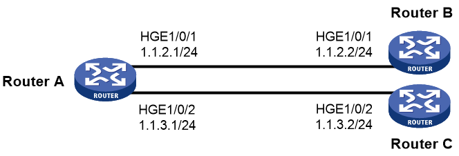
Network configuration
As shown in Figure 1, Router B and Router C do not have a route to reach each other.
Configure PBR on Router A to forward all TCP packets to the next hop 1.1.2.2 (Router B).
Procedure
|
|
IMPORTANT: By default, interfaces on the device are disabled (in ADM or Administratively Down state). To have an interface operate, you must use the undo shutdown command to enable that interface. |
1. Configure Router A:
# Configure the IP addresses of HundredGigE 1/0/1 and HundredGigE 1/0/2.
<RouterA> system-view
[RouterA] interface hundredgige 1/0/1
[RouterA-HundredGigE1/0/1] ip address 1.1.2.1 24
[RouterA-HundredGigE1/0/1] quit
[RouterA] interface hundredgige 1/0/2
[RouterA-HundredGigE1/0/2] ip address 1.1.3.1 24
[RouterA-HundredGigE1/0/2] quit
# Configure ACL 3101 to match TCP packets.
[RouterA] acl advanced 3101
[RouterA-acl-ipv4-adv-3101] rule permit tcp
[RouterA-acl-ipv4-adv-3101] quit
# Configure Node 5 for the policy aaa to forward TCP packets to next hop 1.1.2.2.
[RouterA] policy-based-route aaa permit node 5
[RouterA-pbr-aaa-5] if-match acl 3101
[RouterA-pbr-aaa-5] apply next-hop 1.1.2.2
[RouterA-pbr-aaa-5] quit
# Configure local PBR by applying the policy aaa to Router A.
[RouterA] ip local policy-based-route aaa
2. On Router B, configure the IP address of HundredGigE 1/0/1.
<RouterB> system-view
[RouterB] interface hundredgige 1/0/1
[RouterB-HundredGigE1/0/1] ip address 1.1.2.2 24
3. On Router C, configure the IP address of HundredGigE 1/0/2.
<RouterC> system-view
[RouterC] interface hundredgige 1/0/2
[RouterC-HundredGigE1/0/2] ip address 1.1.3.2 24
Verifying the configuration
1. Perform telnet operations to verify that local PBR on Router A operates as configured to forward the matching TCP packets to the next hop 1.1.2.2 (Router B), as follows:
# Verify that you can telnet to Router B from Router A successfully. (Details not shown.)
# Verify that you cannot telnet to Router C from Router A. (Details not shown.)
2. Verify that Router A forwards packets other than TCP packets through HundredGigE 1/0/2. For example, verify that you can ping Router C from Router A. (Details not shown.)
Example: Configuring packet type-based interface PBR
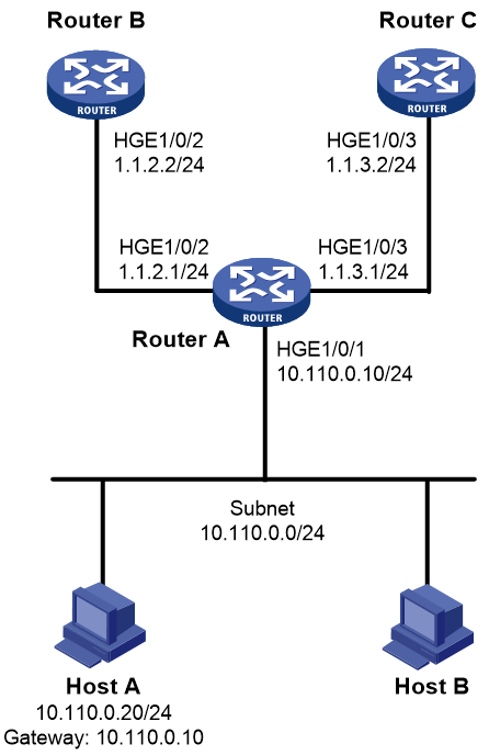
Network configuration
As shown in Figure 2, Router B and Router C do not have a route to reach each other.
Configure PBR on Router A to forward all TCP packets received on HundredGigE 1/0/1 to the next hop 1.1.2.2 (Router B).
Procedure
|
|
IMPORTANT: By default, interfaces on the device are disabled (in ADM or Administratively Down state). To have an interface operate, you must use the undo shutdown command to enable that interface. |
1. Configure IP addresses and unicast routing protocol settings to make sure Router B and Router C can reach Host A. (Details not shown.)
2. Configure Router A:
# Configure ACL 3101 to match TCP packets.
[RouterA] acl advanced 3101
[RouterA-acl-ipv4-adv-3101] rule permit tcp
[RouterA-acl-ipv4-adv-3101] quit
# Configure Node 5 for the policy aaa to forward TCP packets to next hop 1.1.2.2.
[RouterA] policy-based-route aaa permit node 5
[RouterA-pbr-aaa-5] if-match acl 3101
[RouterA-pbr-aaa-5] apply next-hop 1.1.2.2
[RouterA-pbr-aaa-5] quit
# Configure interface PBR by applying the policy aaa to HundredGigE 1/0/1.
[RouterA] interface hundredgige 1/0/1
[RouterA-HundredGigE1/0/1] ip policy-based-route aaa
[RouterA-HundredGigE1/0/1] quit
Verifying the configuration
1. Perform telnet operations to verify that interface PBR on Router A operates as configured to forward the matching TCP packets to the next hop 1.1.2.2 (Router B), as follows:
# Verify that you can telnet to Router B from Host A successfully. (Details not shown.)
# Verify that you cannot telnet to Router C from Host A. (Details not shown.)
2. Verify that Router A forwards packets other than TCP packets through HundredGigE 1/0/3. For example, verify that you can ping Router C from Host A. (Details not shown.)
Example: Configuring source-IP-based interface PBR
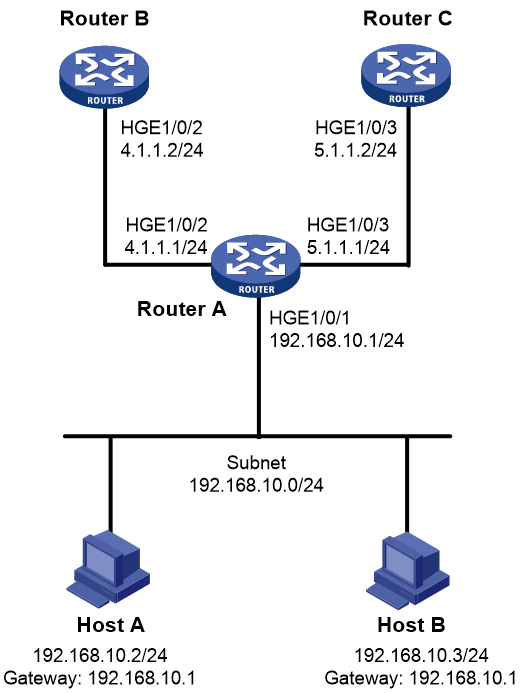
Network configuration
As shown in Figure 3, Router B and Router C do not have a route to reach each other.
Configure interface PBR to guide the forwarding of packets received on HundredGigE 1/0/1 of Router A as follows:
· Set the next hop of packets sourced from 192.168.10.2 to 4.1.1.2/24.
· Set the next hop of other packets to 5.1.1.2/24.
Procedure
|
|
IMPORTANT: By default, interfaces on the device are disabled (in ADM or Administratively Down state). To have an interface operate, you must use the undo shutdown command to enable that interface. |
1. Configure IP addresses and unicast routing protocol settings to make sure Router B can reach Host A and Host B, and Router C can reach Host A and Host B. (Details not shown.)
2. Configure Router A:
# Configure ACL 2000 to match packets sourced from 192.168.10.2.
[RouterA] acl basic 2000
[RouterA-acl-ipv4-basic-2000] rule 10 permit source 192.168.10.2 0
[RouterA-acl-ipv4-basic-2000] quit
# Configure Node 0 for the policy aaa to forward packets sourced from 192.168.10.2 to next hop 4.1.1.2. Configure Node 1 for the policy aaa to forward other packets to next hop 5.1.1.2.
[RouterA] policy-based-route aaa permit node 0
[RouterA-pbr-aaa-0] if-match acl 2000
[RouterA-pbr-aaa-0] apply next-hop 4.1.1.2
[RouterA-pbr-aaa-0] quit
[RouterA] policy-based-route aaa permit node 1
[RouterA-pbr-aaa-1] apply next-hop 5.1.1.2
[RouterA-pbr-aaa-1] quit
# Configure interface PBR by applying the policy aaa to HundredGigE 1/0/1.
[RouterA] interface hundredgige 1/0/1
[RouterA-HundredGigE1/0/1] ip policy-based-route aaa
[RouterA-HundredGigE1/0/1] quit
Verifying the configuration
1. Verify that interface PBR on Router A operates as configured to forward packets sourced from 192.168.10.2 to the next hop 4.1.1.2 and packets sourced from 192.168.10.3 to the next hop 5.1.1.2:
# Configure IP address 192.168.10.3/24 for Host B, and specify its gateway address as 192.168.10.1. (Details not shown.)
# Verify that you can ping Router B from Host A. (Details not shown.)
# Verify that you can ping Router C from Host B. (Details not shown.)
# Verify that you cannot ping Router B from Host B. (Details not shown.)
# Verify that you cannot ping Router C from Host A. (Details not shown.)
