- Table of Contents
-
- H3C Data Center Switches DRNI Configuration Guide-6W103
- 00-DRNI network planning
- 01-DRNI+IPv4 and IPv6 Dual-Active VLAN Gateway Configuration Example
- 02-Multi-Layer DRNI+STP+Dual-Active VLAN Gateway Configuration Examples
- 03-Multi-Layer DRNI+Dual-Active VLAN Gateway+OSPF Configuration Examples
- 04-Multi-tier DRNI+Spine Gateways+ECMP Paths to External Network Configuration Example
- 05-DRNI and VRRP Configuration Example
- 06-DRNI+RDMA Configuration Example
- 07-DRNI and EVPN Distributed Gateway (IS-IS for underlay routing) Configuration Example
- 08-DRNI and EVPN Distributed Gateway (BGP for Underlay Routing) Configuration Example
- 09-DRNI+EVPN Distributed Gateway (OSPF on Underlay Network)+DHCP Relay+Microsegmentation+Service Chain Configuration Example
- 10-DRNI+EVPN Centralized Gateway Configuration Example
- 11-Access to DRNI Through Dynamic Routing and Distributed EVPN Gateways Configuration Example
- 12-DRNI+EVPN+Monitor Link Configuration Examples
- 13-DRNI and MVXLAN Configuration Example
- 14-DRNI and DCI Configuration Example
- 15-DRNI+EVPN DC Switchover Upon Border Failure Configuration Examples
- Related Documents
-
| Title | Size | Download |
|---|---|---|
| 15-DRNI+EVPN DC Switchover Upon Border Failure Configuration Examples | 532.33 KB |
Introduction
The following information provides a data center (DC) switchover solution upon border device failure in the EVPN + DRNI networking.
This document applies to the following application scenarios:
· For the two border devices in a DC, all member ports of a DR interface go down. This scenario requires switchover for only the traffic on the faulty DR interface to the backup DC. Other traffic do not require switchover.
· All spine device-attached ports on the two border devices go down. The solution described in this document does not apply to this fault scenario if an integrated border and spine device is deployed in the network.
· Both border devices become faulty. The solution described in this document does not apply to this fault scenario if an integrated border and spine device is deployed in the network.
|
|
NOTE: This document provides the configuration for traffic switchover to the backup DC when one of the border device failures occurs. For more information about recovering the DR interface, IPL, keepalive, or public network interface failure on a border device or recovering failure of a single border device, see the EVPN+DRNI configuration examples. |
This document provides the following configuration examples based on the connections between the border devices and the external networks.
Example: Using multiple DR interfaces on the border devices as the outbound interfaces to external networks
Network configuration
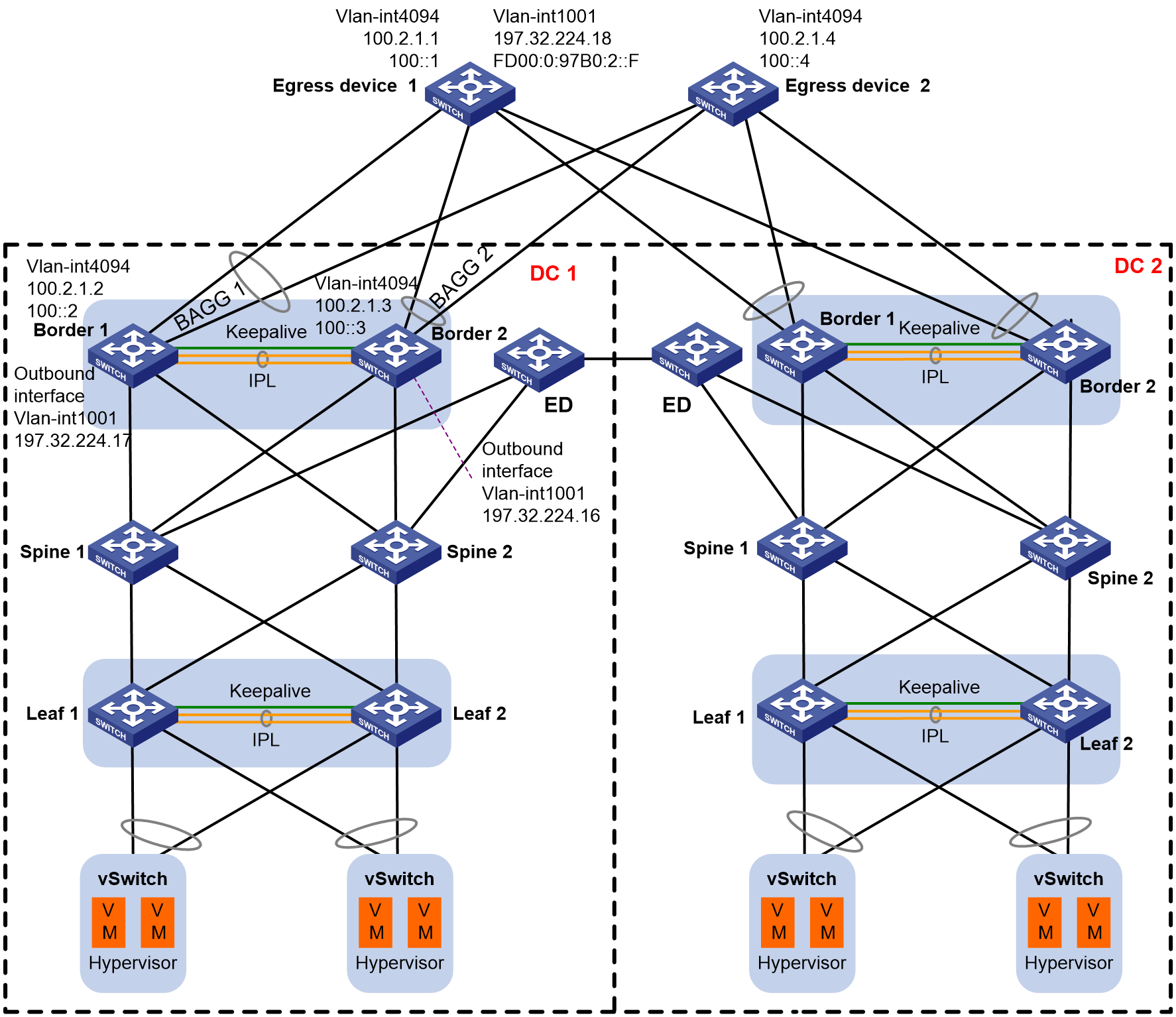
As shown in Figure 1, two DCs adopt the EVPN+DRNI networking, and they are interconnected through the VXLAN-DCI tunnel established on ED devices. DC 2 acts as the backup for DC 1. Configure static routes on the border devices to communicate with the external networks. The border devices in DC 1 are connected to different uplink egress devices through multiple DR interfaces. Egress device 1 and egress device 2 are connected to different external networks.
When one of the following situations occurs in DC 1, make sure traffic can switch over to the border devices in DC 2:
· For the two border devices in DC 1, all member ports of a DR interface go down. This situation requires switchover of only the traffic on the faulty DR interface to the backup DC. Other traffic do not require switchover.
· All spine device-attached ports on the two border devices go down.
· Both border devices become faulty.
Analysis
The border device has multiple DR interfaces. Connect each DR interface to an external network. When the same DR interface on the two border devices fails, only the outbound traffic on the faulty DR interface requires switchover. Other traffic do not require switchover. Do not shut down the border device interfaces attached to the spine devices. If you shut down such interfaces, all outbound traffic will be switched over.
To meet these requirements, configure collaboration between NQA, Track, and default static routes (IPv4 and IPv6) as follows:
· Configure a default static route on the border device, with the IP address of VLAN-interface 1001 as the next hop.
· Configure an ICMP-echo NQA operation to detect the connectivity between the border device and egress device.
· Configure a track entry to associate the NQA operation with the static route. When NQA detects a connection failure between the border device and the egress device, the static route is withdrawn.
When a member port of a DR interface on Border 1 goes down and the corresponding member port of the DR interface on Border 2 is up, ICMP packets can go through the IPL. NQA will not trigger track entry state change. When the physical member ports of DR interfaces on both border devices go down, NQA on the border devices can detect failure of the connections to the egress device. Track will then notify the devices to withdraw the static routes on the DR interfaces. The route information change will be synchronized to the remote leaf devices. The remote leaf devices will not forward outbound traffic to this group of border devices. Traffic on other DR interfaces on the border devices will not be affected because they are still in up state.
Applicable product matrix
|
|
IMPORTANT: In addition to running an applicable software version, you must also install the most recent patch, if any. |
|
Device |
Software version |
|
S6805, S6825, S6850, S9850 |
R6635 |
|
S6800, S6860 |
F2715 and higher F27xx versions. Do not use F28xx versions. |
|
S12500X-AF, S6890 |
R2820 |
|
S12500G-AF |
Contact H3C Support to obtain compatible versions. |
|
S9820-64H, S9820-8C |
Not supported |
|
S6812, S6813 |
Not supported |
Restrictions and guidelines
You need to create the same VLAN interfaces on the egress devices as those on the failover link, and configure different IP addresses for these VLAN interfaces. This configuration ensures that the entries created by ARP responses from the IPP can be synchronized to the DR interfaces. Without this configuration, NQA cannot detect DR interface failure. This is because NQA probe packets can be forwarded through the IPL.
Procedure
This example describes the configuration for traffic switchover upon failures when the border devices use multiple DR interfaces as the outbound interfaces to the external network. The settings include VLAN-interface 4094 for the failover link, as well as collaboration between NQA, Track, and default static routes. The settings of EVPN, VXLAN, and data center interconnection are omitted.
Configuring border devices
|
Border 1 |
Border 2 |
Description |
|
ip vpn-instance external_vpn_1001 |
ip vpn-instance external_vpn_1001 |
Create external network VPN instance external_vpn_1001 and enter VPN instance view. |
|
quit |
quit |
Return to system view. |
|
interface bridge-aggregation 1 |
interface bridge-aggregation 1 |
Create Layer 2 aggregation group 1, which will be used as the DR aggregation group. |
|
port link-type trunk |
port link-type trunk |
Set the link type of Bridge-Aggregation 1 to trunk. |
|
undo port trunk permit vlan 1 |
undo port trunk permit vlan 1 |
Forbid traffic of VLAN 1 to pass through the trunk port. |
|
port trunk permit vlan 1001 4094 |
port trunk permit vlan 1001 4094 |
Assign the trunk port to VLAN 1001 and VLAN 4094. |
|
link-aggregation mode dynamic |
link-aggregation mode dynamic |
Configure the aggregate interface to operate in dynamic mode. |
|
port drni group 2 |
port drni group 2 |
Assign the Bridge-Aggregation 1 to DR group 2. |
|
interface vlan-interface 4094 |
interface vlan-interface 4094 |
Create VLAN-interface 4094 used as the failover link. |
|
ip address 100.2.1.2 255.255.255.0 |
ip address 100.2.1.3 255.255.255.0 |
Configure the IPv4 address for the failover link. |
|
ipv6 address 100::2/64 |
ipv6 address 100::3/64 |
Configure the IPv6 address for the failover link. |
|
ospf 65530 area 0.0.0.0 |
ospf 65530 area 0.0.0.0 |
Enable OSPF to create routes for failover between the two DR devices. |
|
quit |
quit |
Return to system view. |
|
interface Vlan-interface 1001 |
interface Vlan-interface 1001 |
Enter the view of VLAN-interface 1001 directly connected to the external network. |
|
ip address 197.32.224.17 255.255.255.252 |
ip address 197.32.224.16 255.255.255.252 |
Configure an IPv4 address for VLAN-interface 4094 connected to the external network. |
|
ip binding vpn-instance external_vpn_1001 |
ip binding vpn-instance external_vpn_1001 |
Bind an external network VPN instance. |
|
ipv6 address FD00:0:97B0:2::E/64 |
ipv6 address FD00:0:97B0:2::D/64 |
Configure an IPv6 address for VLAN-interface 4094 connected to the external network. |
|
quit |
quit |
Return to system view. |
|
nqa entry admin1 lable1 |
nqa entry admin1 lable1 |
Create NQA operation admin1-lable1 and enter its view. |
|
type icmp-echo |
type icmp-echo |
Specify the ICMP echo operation type and enter its view. |
|
destination ip 100.2.1.1 |
destination ip 100.2.1.1 |
Specify the destination IPv4 address as the IP address of VLAN-interface 4094 on the egress device. |
|
frequency 500 |
frequency 500 |
Configure the NQA operation to repeat every 500 milliseconds. |
|
reaction 1 checked-element probe-fail threshold-type consecutive 1 action-type trigger-only |
reaction 1 checked-element probe-fail threshold-type consecutive 1 action-type trigger-only |
# Create reaction entry 1. If the number of consecutive probe failures reaches 1, collaboration is triggered. |
|
source ip 100.2.1.2 |
source ip 100.2.1.3 |
Specify the source IPv4 address for the NQA operation as the IP address of VLAN-interface 4094. |
|
quit |
quit |
Return to the view of NQA operation admin1-lable1. |
|
quit |
quit |
Return to system view. |
|
nqa entry admin2 lable2 |
nqa entry admin2 lable2 |
Create NQA operation admin2-lable2 and enter its view. |
|
type icmp-echo |
type icmp-echo |
Specify the ICMP echo operation type. |
|
destination ipv6 100::1 |
destination ipv6 100::1 |
Specify the destination IPv6 address as the IPv6 address of VLAN-interface 4094 on the egress device. |
|
frequency 500 |
frequency 500 |
Configure the NQA operation to repeat every 500 milliseconds. |
|
reaction 1 checked-element probe-fail threshold-type consecutive 1 action-type trigger-only |
reaction 1 checked-element probe-fail threshold-type consecutive 1 action-type trigger-only |
Create reaction entry 1. If the number of consecutive probe failures reaches 1, collaboration is triggered. |
|
source ipv6 100::2 |
source ipv6 100::3 |
Specify the source IPv6 address as the IPv6 address of VLAN-interface 4094. |
|
quit |
quit |
Return to the view of NQA operation admin2-lable2. |
|
quit |
quit |
Return to system view. |
|
track11 nqa entry admin1 lable1 reaction 1 |
track11 nqa entry admin1 lable1 reaction 1 |
Associate NQA operation admin1-lable1 with track entry 11, and enter Track view. |
|
quit |
quit |
Return to system view. |
|
track12 nqa entry admin2 lable2 reaction 1 |
track12 nqa entry admin2 lable2 reaction 1 |
Associate NQA operation admin2-lable2 with track entry 12, and enter Track view. |
|
quit |
quit |
Return to system view. |
|
ip vpn-instance USERVRF |
ip vpn-instance USERVRF |
Create internal network VPN instance USERVRF and enter VPN instance view. |
|
quit |
quit |
Return to system view. |
|
ip route-static vpn-instance USERVRF 0.0.0.0 0 vpn-instance external_vpn_1001 197.32.224.18 track 11 preference 1 |
ip route-static vpn-instance USERVRF 0.0.0.0 0 vpn-instance external_vpn_1001 197.32.224.18 track 11 preference 1 |
Create an IPv4 static route, specify the next hop on the border device to the external network as 197.32.224.18 (IPv4 address of VLAN-interface 1001 on the egress device), and associate the static route with track entry 11. |
|
ipv6 route-static vpn-instance USERVRF ::0 vpn-instance external_vpn_1001 FD00:0:97B0:2::F track 12 preference 1 |
ipv6 route-static vpn-instance USERVRF ::0 vpn-instance external_vpn_1001 FD00:0:97B0:2::F track 12 preference 1 |
Create an IPv6 static route, specify the next hop on the border device to the external network as FD00:0:97B0:2::F (IPv6 address of VLAN-interface 1001 on the egress device), and associate the static route with track entry 12. |
|
nqa schedule admin1 lable1 start-time now lifetime forever |
nqa schedule admin1 lable1 start-time now lifetime forever |
Schedule the operation with administrator name admin1. |
|
nqa schedule admin2 lable2 start-time now lifetime forever |
nqa schedule admin2 lable2 start-time now lifetime forever |
Schedule the operation with administrator name admin2. |
Configure egress devices
The egress devices reside in the Internet and third-party external connection area. Egress device configuration typically includes dynamic aggregate interfaces connected to border devices, failover link, and next hop interface on the border device to the external network.
Table 1 Configuring egress devices
|
Egress device |
Description |
|
interface bridge-aggregation 2 |
Configure the aggregate interface connected to the DR interfaces on Border 1 and Border 2. |
|
port link-type trunk |
Set the link type of the aggregate interface to trunk. |
|
undo port trunk permit vlan 1 |
Forbid traffic of VLAN 1 to pass through the trunk port. |
|
port trunk permit vlan 1001 4094 |
Assign the trunk port to VLAN 1001 and VLAN 4094. |
|
link-aggregation mode dynamic |
Configure the aggregate interface to operate in dynamic mode. |
|
quit |
Return to system view. |
|
interface vlan-interface 4094 |
Configure the failover link interface. |
|
ip address 100.2.1.1 255.255.255.0 |
Configure the IPv4 address for the failover link. |
|
ipv6 address 100::1/64 |
Configure the IPv6 address for the failover link. |
|
quit |
Return to system view. |
|
interface vlan-interface 1001 |
Configure the next hop address on the border device to the external network. |
|
ip address 197.32.224.18 255.255.255.252 |
Configure an IPv4 address for VLAN-interface 1001, that is, the next hop IPv4 address on the border device to the external network. |
|
ipv6 address FD00:0:97B0:2::F/64 |
Configure an IPv6 address for VLAN-interface 1001, that is, the next hop IPv6 address on the border device to the external network. |
|
quit |
Return to system view. |
Verifying failure recovery
Shut down the DR member port on one border device (Border 1, for example). Traffic can be forwarded through the IPL, the track entry state is Positive, and the default static route is still active. VLAN-interface 1001 and VLAN-interface 4094 on the egress device can learn the ARP and ND entries from the DR interface, and no packet loss occurs.
As shown in Figure 2, the traffic from the server to the external network is forwarded through the IPL to the egress device.
Figure 2 Failure recovery for the DR member port on Border 1

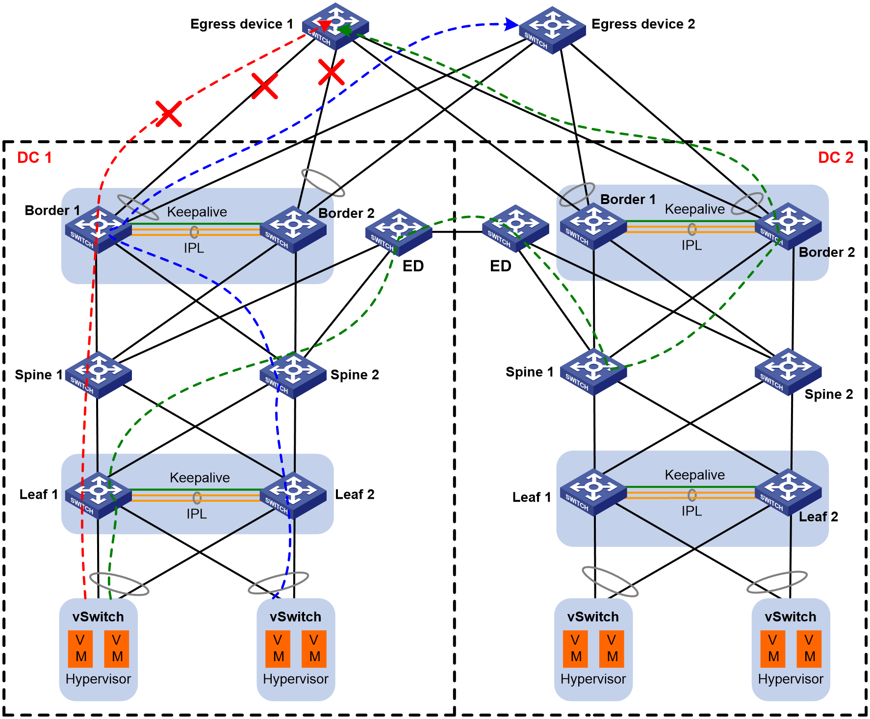
As shown in Figure 3, shut down all member ports of BAGG1 on both Border 1 and Border 2 in DC 1. The static route marked with a red line is withdrawn (with BAGG1 on Border 1 and Border 2 as the output interface, and IP address of VLAN-interface 1001 on egress device 1 as the next hop). The changed route information is then synchronized to the leaf devices. The outbound traffic the previously forwarded through BAGG1 on Border 1 and Border 2 will be switched over to the border device in DC 2 (the traffic path is marked with a green line).
The interface status of BAGG2 on Border 1 and Border 2 in DC 1 and the default static route are not changed. The path (marked with a blue line) is not changed for outbound traffic forwarded through BAGG2 on Border 1 and Border 2.
Figure 3 Failure recovery the DR member ports on both Border 1 and Border 2
Example: Connecting the border devices to the external network with multiple Layer 3 Ethernet interfaces
Network configuration
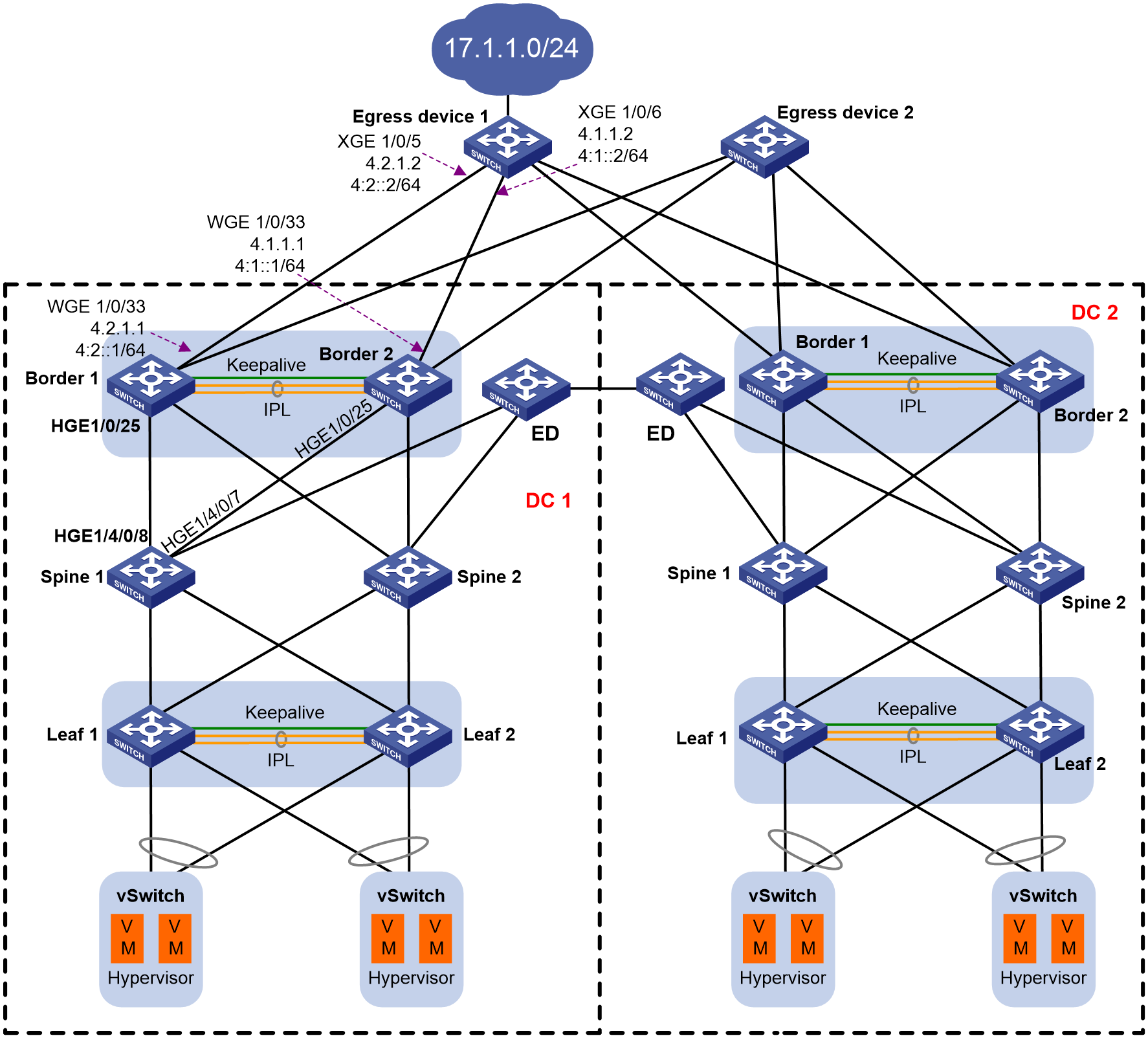
As shown in Figure 4, two data centers adopt the EVPN+DRNI networking, and they are interconnected through the VXLAN-DCI tunnel established between ED devices. DC 2 acts as the backup for DC 1. The border devices are connected to different uplink egress devices through multiple Layer 3 Ethernet interfaces. Egress device 1 and egress device 2 are connected to different external networks.
When one of the following situations occurs in DC 1, make sure traffic can switch over to the border devices in DC 2:
· On the two border devices in DC 1, both Layer 3 Ethernet interfaces connected to the same egress device go down.
· All spine device-attached ports on the two border devices go down.
· Both border devices become faulty.
Analysis
Route setup for northbound traffic
1. Configure a default IPv4/IPv6 static route (with the ip route-static 0.0.0.0 0 NULL0 command) on the egress device. Configure OSPF/OSPFv3 to advertise the default static route to the border device. The border device will forward traffic matching the default route through the Layer 3 interface connected to the egress device.
In this solution, the default static route is not deployed to the border device. If the default static route is deployed to the border device, the IP address of the interface on the border device directly connected to the egress device is used as the next hop. When the direct link fails, the next hop no longer exists, and the default static route becomes invalid and is withdrawn. Then the traffic sent by the leaf device can enter the border device through the DRNI group IP address. With a private network failover link configured, traffic can be forwarded through the IPL. However, such a situation has long convergence time and is not as expected.
2. Configure a routing policy on the border device to deny all routes except the default route received from the egress device.
This configuration saves route resources and prevents the border device from receiving other unnecessary static routes from the egress device.
3. The border device redistributes the default route to the internal network VPN and then into BGP. Then it advertises the route to the leaf device.
4. The leaf device accepts only the default route. Northbound traffic will be forwarded through the default route.
Figure 5 Route setup for northbound traffic

Route setup for southbound traffic
1. Create a static route between the egress device and DC 1/DC 2, and associate the static routes with a track entry. Set a higher priority for the static route to DC 1. Southbound traffic are preferentially forwarded through DC 1. When NQA detects that all links connected to DC 1 fail, the static route (to DC 2) with lower priority takes effect. Southbound traffic will be switched over to DC 2.
2. Replicate internal network VPN route on the border device to external network VPN, and send the route of the leaf device to the egress device. Upon entering the egress device, southbound traffic will be forwarded to the leaf device through the border device.
Failover link configuration
1. Create VLAN-interface 4093 for the failover link on the border device and bind it to the external network VPN.
2. In addition, bind the interface connected to the external network on the border device to the external network VPN.
Applicable product matrix
|
|
IMPORTANT: In addition to running an applicable software version, you must also install the most recent patch, if any. |
|
Device |
Software version |
|
S6805, S6825, S6850, S9850 |
R6635 |
|
S6800, S6860 |
F2715 and higher F27xx versions. Do not use F28xx versions. |
|
S12500X-AF, S6890 |
R2820 |
|
S12500G-AF |
Contact H3C Support to obtain compatible versions. |
|
S9820-64H, S9820-8C |
Not supported |
|
S6812, S6813 |
Not supported |
Restrictions and guidelines
· Replicate OSPF routes of the external network VPN to the internal network VPN, and configure a routing policy to redistribute only the default route. Do not redistribute routes with RT. The redistributed routes cannot be reoriginated as EVPN routes.
· To correctly forward southbound traffic, advertise routes of the leaf device to the border device and then to the egress device.
· To correctly forward northbound traffic, replicate routes of the external network VPN to the internal network VPN. Delete configuration associated with RTs to avoid routing loops.
· Configure the spf-schedule-interval 1 10 10 command in OSPF/OSPFv3 view. This configuration addresses the packet loss issue when the following conditions occur in sequence:
¡ The outbound interface to the external network on Border 2 in DC 1 goes down.
¡ The outbound interface to the external network on Border 1 goes down.
¡ The outbound interface to the external network on Border 1 comes up.
¡ Traffic switches over from the border device in DC 2 to Border 1 and Border 2 in DC 1.
During this process, when the outbound interface to the external network on Border 1 comes up, Border 1 first establishes OSPF/OSPFv3 neighbors with the egress device, and then receives the default static route from the egress device. Because failover link between Border 1 and Border 2 keeps up, the default static route will be immediately sent to Border 2. During this process, if flapping occurs for the outbound interface to the external network on Border 1, the SPF calculation interval increases by an incremental interval of 200 ms (up to 5 seconds) for OSPF/OSPFv3 in the private network. If no OSPF/OSPFv3 neighbor flapping occurs on Border 2, the calculated route is immediately sent to the remote leaf device. The remote leaf device then immediately switches traffic to the border device in DC 1 that has not completed SPF calculation. No such default route entry exists, and packet loss occurs.
· In this configuration solution, the border devices do not have DR interfaces. DRNI MAD shutdown does not take effect upon reboot of the border device. The current software version does not support the workaround by configuring empty DR interfaces. When Border 1 reboots or both Border 1 and Border 2 reboot, reserve enough time for route synchronization. To do that, configure a delay up timer on the uplink and downlink interfaces of the border device. On the border device, set the delay up timer for the interface connected to the spine device to 150 seconds, and set the delay up timer for the interface connected to the egress device to 300 seconds. This configuration enables the interface between the border and spine to come up first, establish BGP neighbors, and then synchronize routes.
· Add the uplink and downlink interfaces on the border device to DRNI MAD shutdown.
Procedure
Configuring border devices
|
Border 1 |
Border 2 |
Description |
|
ip vpn-instance external_vpn_1001 |
ip vpn-instance external_vpn_1001 |
Create external network VPN instance external_vpn_1001 and enter VPN instance view. |
|
quit |
quit |
Return to system view. |
|
ip vpn-instance external_vpn_1002 |
ip vpn-instance external_vpn_1002 |
Create external network VPN instance external_vpn_1002 and enter VPN instance view. |
|
quit |
quit |
Return to system view. |
|
ospf 1 router-id 100.3.1.2 vpn-instance external_vpn_1001 |
ospf 1 router-id 100.3.1.3 vpn-instance external_vpn_1001 |
Enable OSPF for the external network VPN. |
|
spf-schedule-interval 1 10 10 |
spf-schedule-interval 1 10 10 |
Set the maximum SPF calculation interval, minimum interval, and incremental interval. |
|
area 0.0.0.0 |
area 0.0.0.0 |
Create an OSPF area. |
|
ospfv3 1 vpn-instance external_vpn_1001 |
ospfv3 1 vpn-instance external_vpn_1001 |
Enable OSPFv3 for the external network VPN. |
|
router-id 4.2.1.1 |
router-id 4.1.1.1 |
Configure a router ID. |
|
spf-schedule-interval 1 10 10 |
spf-schedule-interval 1 10 10 |
Set the maximum SPF calculation interval, minimum interval, and incremental interval. |
|
quit |
quit |
Return to system view. |
|
interface vlan-interface 4093 |
interface vlan-interface 4093 |
Configure a VLAN interface for the failover link. |
|
ip binding vpn-instance external_vpn_1001 |
ip binding vpn-instance external_vpn_1001 |
Bind an external network VPN instance. |
|
ip address 100.3.1.2 255.255.255.0 |
ip address 100.3.1.3 255.255.255.0 |
Assign an IPv4 address to the interface. |
|
ospf 1 area 0.0.0.0 |
ospf 1 area 0.0.0.0 |
Enable OSPF for the interface. |
|
ospf peer hold-max-cost duration 300000 |
ospf peer hold-max-cost duration 300000 |
Enable OSPF to advertise the maximum link cost to neighbors within 300000 milliseconds. |
|
ospfv3 1 area 0.0.0.0 |
ospfv3 1 area 0.0.0.0 |
Enable OSPFv3 for the interface. |
|
ospfv3 peer hold-max-cost duration 300000 |
ospfv3 peer hold-max-cost duration 300000 |
Enable OSPFv3 to advertise the maximum link cost to neighbors within 300000 milliseconds. |
|
ipv6 address 100:1::2/64 |
ipv6 address 100:1::3/64 |
Assign an IPv6 address to the interface. |
|
quit |
quit |
N/A |
|
ip prefix-list ipv4-def permit 0.0.0.0 0 |
ip prefix-list ipv4-def permit 0.0.0.0 0 |
Configure an IPv4 prefix list to permit the default route.
|
|
ipv6 prefix-list ipv6-def permit 0::0 0 |
ipv6 prefix-list ipv6-def permit 0::0 0 |
Configure an IPv6 prefix list to permit the default route.
|
|
ip prefix-list SDNCIDR_DENY_IPv4 deny 0.0.0.0 0 less-equal 32 |
ip prefix-list SDNCIDR_DENY_IPv4 deny 0.0.0.0 0 less-equal 32 |
Configure an IPv4 prefix list to deny non-default routes.
|
|
ipv6 prefix-list SDNCIDR_DENY_IPv6 deny 0::0 0 less-equal 128 |
ipv6 prefix-list SDNCIDR_DENY_IPv6 deny 0::0 0 less-equal 128 |
Configure an IPv6 prefix list to deny non-default routes.
|
|
route-policy ipv4-def permit node 10 |
route-policy ipv4-def permit node 10 |
Configure a routing policy. |
|
if-match ip address prefix-list ipv4-def |
if-match ip address prefix-list ipv4-def |
Match an IPv4 prefix list. |
|
route-policy ipv4-def deny node 20 |
route-policy ipv4-def deny node 20 |
Configure a routing policy. |
|
if-match ip address prefix-list SDNCIDR_DENY_IPv4 |
if-match ip address prefix-list SDNCIDR_DENY_IPv4 |
Match an IPv4 prefix list. |
|
route-policy ipv6-def permit node 10 |
route-policy ipv6-def permit node 10 |
Configure a routing policy. |
|
if-match ipv6 address prefix-list ipv6-def |
if-match ipv6 address prefix-list ipv6-def |
Match an IPv6 prefix list. |
|
route-policy ipv6-def deny node 20 |
route-policy ipv6-def deny node 20 |
Configure a routing policy. |
|
if-match ipv6 address prefix-list SDNCIDR_DENY_IPv6 |
if-match ipv6 address prefix-list SDNCIDR_DENY_IPv6 |
Match an IPv6 prefix list. |
|
ip vpn-instance USERVRF |
ip vpn-instance USERVRF |
Create a BGP-VPN instance and enter BGP-VPN instance view. |
|
address-family ipv4 |
address-family ipv4 |
Enter VPN instance IPv4 address family view. |
|
route-replicate from vpn-instance external_vpn_1001 protocol ospf 1 advertise route-policy ipv4-def |
route-replicate from vpn-instance external_vpn_1001 protocol ospf 1 advertise route-policy ipv4-def |
Replicate OSPF routes from the internal network VPN to the external network. |
|
route-replicate from vpn-instance external_vpn_1002 protocol ospf 1 advertise route-policy ipv4-def |
route-replicate from vpn-instance external_vpn_1002 protocol ospf 1 advertise route-policy ipv4-def |
Replicate OSPF routes from the internal network VPN to the external network. |
|
address-family ipv6 |
address-family ipv6 |
Enter VPN instance IPv6 address family view. |
|
route-replicate from vpn-instance external_vpn_1001 protocol ospfv3 1 advertise route-policy ipv6-def |
route-replicate from vpn-instance external_vpn_1001 protocol ospfv3 1 advertise route-policy ipv6-def |
Replicate OSPFv3 routes from the internal network VPN to the external network. |
|
route-replicate from vpn-instance external_vpn_1002 protocol ospfv3 1 advertise route-policy ipv6-def |
route-replicate from vpn-instance external_vpn_1002 protocol ospfv3 1 advertise route-policy ipv6-def |
Replicate OSPFv3 routes from the internal network VPN to the external network. |
|
bgp 65530 |
bgp 65530 |
Enter BGP view. |
|
ip vpn-instance USERVRF |
ip vpn-instance USERVRF |
Create a BGP-VPN instance and enter BGP-VPN instance view. |
|
address-family ipv4 |
address-family ipv4 |
Enter VPN instance IPv4 address family view. |
|
import-route ospf 1 allow-direct |
import-route ospf 1 allow-direct |
Redistribute OSPF routes to the internal network VPN of BGP. |
|
address-family ipv6 |
address-family ipv6 |
Enter VPN instance IPv6 address family view. |
|
import-route ospfv3 1 allow-direct |
import-route ospfv3 1 allow-direct |
Redistribute OSPFv3 routes to the internal network VPN of BGP. |
|
ip vpn-instance external_vpn_1001 |
ip vpn-instance external_vpn_1001 |
Create a BGP-VPN instance and enter BGP-VPN instance view. |
|
address-family ipv4 |
address-family ipv4 |
Enter VPN instance IPv4 address family view. |
|
route-replicate from vpn-instance USERVRF protocol bgp 65530 advertise |
route-replicate from vpn-instance USERVRF protocol bgp 65530 advertise |
Replicate internal network IPv4 routes to BGP and advertise the routes. |
|
address-family ipv6 |
address-family ipv6 |
Enter VPN instance IPv6 address family view. |
|
route-replicate from vpn-instance USERVRF protocol bgp4+ 65530 advertise |
route-replicate from vpn-instance USERVRF protocol bgp4+ 65530 advertise |
Replicate internal network IPv6 routes to BGP and advertise the routes. |
|
quit |
quit |
Return to BGP-VPN instance view. |
|
quit |
quit |
Return to BGP view. |
|
quit |
quit |
Return to system view. |
|
ospf 1 router-id 100.3.1.2 vpn-instance external_vpn_1001 |
ospf 1 router-id 100.3.1.3 vpn-instance external_vpn_1001 |
Enable OSPF for the external network VPN. |
|
filter-policy route-policy ipv4-def import |
filter-policy route-policy ipv4-def import |
Configure a filtering policy to deploy only the default route to the routing table. |
|
quit |
quit |
Return to system view. |
|
ospfv3 1 vpn-instance external_vpn_1001 |
ospfv3 1 vpn-instance external_vpn_1001 |
Enable OSPFv3 for the external network VPN. |
|
router-id 4.2.1.1 |
router-id 4.1.1.1 |
Configure a router ID. |
|
filter-policy route-policy ipv6-def import |
filter-policy route-policy ipv6-def import |
Configure a filtering policy to deploy only the default route to the routing table. |
|
area 0.0.0.0 |
area 0.0.0.0 |
Enter OSPFv3 area view. |
|
quit |
quit |
Return to OSPFv3 view. |
|
quit |
quit |
Return to system view. |
|
interface Twenty-FiveGigE1/0/33 |
interface Twenty-FiveGigE1/0/33 |
Enter the view of the physical interface connected to the egress device. |
|
port link-mode route |
port link-mode route |
Configure the interface to operate in Layer 3 mode. |
|
speed 10000 |
speed 10000 |
Set the same speed as the peer interface. |
|
ip binding vpn-instance external_vpn_1001 |
ip binding vpn-instance external_vpn_1001 |
Bind an external network VPN instance. |
|
ip address 4.2.1.1 255.255.255.0 |
ip address 4.1.1.1 255.255.255.0 |
Assign an IPv4 address to the interface. |
|
ospf 1 area 0.0.0.0 |
ospf 1 area 0.0.0.0 |
Enable OSPF for the interface. |
|
ospf peer hold-max-cost duration 300000 |
ospf peer hold-max-cost duration 300000 |
Enable OSPF to advertise the maximum link cost to neighbors within 300000 milliseconds. |
|
ospfv3 1 area 0.0.0.0 |
ospfv3 1 area 0.0.0.0 |
Enable OSPFv3 for the interface. |
|
ospfv3 peer hold-max-cost duration 300000 |
ospfv3 peer hold-max-cost duration 300000 |
Enable OSPFv3 to advertise the maximum link cost to neighbors within 300000 milliseconds. |
|
lldp compliance admin-status cdp txrx |
lldp compliance admin-status cdp txrx |
Enable CDP-compatible LLDP globally and configure CDP-compatible LLDP to operate in TxRx mode. |
|
ipv6 address 4:1::1/64 |
ipv6 address 4:1::2/64 |
Assign an IPv6 address to the interface. |
|
quit |
quit |
Return to system view. |
|
interface HundredGigE1/0/25 |
interface HundredGigE1/0/25 |
Enter the view of the physical interface connected to the spine device. |
|
port link-mode route |
port link-mode route |
Configure the interface to operate in Layer 3 mode. |
|
link-delay down 0 |
link-delay down 0 |
Set the link-down event suppression interval to 0 seconds. |
|
ip address unnumbered interface LoopBack0 |
ip address unnumbered interface LoopBack0 |
Configure the interface to borrow the IP address of Loopback 0. |
|
ospf network-type p2p |
ospf network-type p2p |
Specify the OSPF network type for the interface as P2P. |
|
ospf 65530 area 0.0.0.0 |
ospf 65530 area 0.0.0.0 |
Enable OSPF for the interface. |
|
ospf peer hold-max-cost duration 300000 |
ospf peer hold-max-cost duration 300000 |
Enable OSPF to advertise the maximum link cost to neighbors within 300000 milliseconds. |
|
lldp compliance admin-status cdp txrx |
lldp compliance admin-status cdp txrx |
Enable CDP-compatible LLDP globally and configure CDP-compatible LLDP to operate in TxRx mode. |
|
lldp management-address arp-learning |
lldp management-address arp-learning |
Enable the device to generate an ARP entry after it receives an LLDP frame that contains a management address TLV on the interface. |
|
lldp tlv-enable basic-tlv management-address-tlv interface LoopBack0 |
lldp tlv-enable basic-tlv management-address-tlv interface LoopBack0 |
Advertise the IP address of Loopback 0 as management address TLVs in LLDP packets. |
|
undo mac-address static source-check enable |
undo mac-address static source-check enable |
Disable the static source check feature on the packet input interface. |
Configure egress devices
|
Egress device 1 |
Description |
|
ip route-static 0.0.0.0 0 NULL0 |
Configure an IPv4 default route. |
|
ipv6 route-static ::0 NULL0 |
Configure an IPv6 default route. |
|
ospf 1 router-id 17.1.1.1 |
Enable OSPF and enter OSPF view. |
|
default-route-advertise |
Advertise the default route. |
|
import-route static |
Redistribute static routes. |
|
area 0.0.0.0 |
Create an OSPF area and enter OSPF area view. |
|
quit |
Return to OSPF view. |
|
quit |
Return to system view. |
|
ospfv3 1 |
Enable OSPFv3. |
|
router-id 4.1.1.2 |
Configure a router ID. |
|
default-route-advertise |
Advertise the default route. |
|
import-route static |
Redistribute static routes. |
|
area 0.0.0.0 |
Create an OSPFv3 area and enter OSPFv3 area view. |
|
quit |
Return to OSPF view. |
|
quit |
Return to system view. |
|
interface Ten-GigabitEthernet1/0/5 |
Enter the view of the interface connected to Border 1. |
|
port link-mode route |
Configure the interface to operate in Layer 3 mode. |
|
ip address 4.2.1.2 255.255.255.0 |
Assign an IPv4 address to the interface. |
|
ospf 1 area 0.0.0.0 |
Enable OSPF for the interface. |
|
ospf peer hold-max-cost duration 300000 |
Enable OSPF to advertise the maximum link cost to neighbors within 300000 milliseconds. |
|
ospfv3 1 area 0.0.0.0 |
Enable OSPFv3 for the interface. |
|
ospfv3 peer hold-max-costduration 300000 |
Enable OSPFv3 to advertise the maximum link cost to neighbors within 300000 milliseconds. |
|
ipv6 address 4:2::2/64 |
Assign an IPv6 address to the interface. |
|
quit |
Return to system view. |
|
interface Ten-GigabitEthernet1/0/6 |
Enter the view of the interface connected to Border 2. |
|
port link-mode route |
Configure the interface to operate in Layer 3 mode. |
|
ip address 4.1.1.2 255.255.255.0 |
Assign an IPv4 address to the interface. |
|
ospf 1 area 0.0.0.0 |
Enable OSPF for the interface. |
|
ospf peer hold-max-cost duration 300000 |
Enable OSPF to advertise the maximum link cost to neighbors within 300000 milliseconds. |
|
ospfv3 1 area 0.0.0.0 |
Enable OSPFv3 for the interface. |
|
ospfv3 peer hold-max-costduration 300000 |
Enable OSPFv3 to advertise the maximum link cost to neighbors within 300000 milliseconds. |
|
ipv6 address 4:1::2/64 |
Assign an IPv6 address to the interface. |
|
quit |
Return to system view. |
|
nqa entry admin1 lable1 |
Create NQA operation admin1-lable1 and enter its view. |
|
type icmp-echo |
Specify the ICMP echo operation type. |
|
destination ip 4.1.1.1 |
Configure the destination IPv4 address for the operation. |
|
frequency 500 |
Configure the NQA operation to repeat every 500 milliseconds. |
|
reaction 1 checked-element probe-fail threshold-type consecutive 1 action-type trigger-only |
Create reaction entry 1. If the number of consecutive probe failures reaches 1, collaboration is triggered. |
|
source ip 4.1.1.2 |
Configure the source IPv4 address for the operation. |
|
nqa entry admin2 lable2 |
Create NQA operation admin2-lable2 and enter its view. |
|
type icmp-echo |
Specify the ICMP echo operation type. |
|
destination ip 4.2.1.1 |
Configure the destination IPv4 address for the operation. |
|
frequency 500 |
Configure the NQA operation to repeat every 500 milliseconds. |
|
reaction 1 checked-element probe-fail threshold-type consecutive 1 action-type trigger-only |
Create reaction entry 1. If the number of consecutive probe failures reaches 1, collaboration is triggered. |
|
source ip 4.2.1.2 |
Configure the source IPv4 address for the operation. |
|
nqa entry admin3 lable3 |
Create NQA operation admin3-lable3 and enter its view. |
|
type icmp-echo |
Specify the ICMP echo operation type. |
|
destination ipv6 4:1::1 |
Configure the destination IPv6 address for the operation. |
|
frequency 500 |
Configure the NQA operation to repeat every 500 milliseconds. |
|
reaction 1 checked-element probe-fail threshold-type consecutive 1 action-type trigger-only |
Create reaction entry 1. If the number of consecutive probe failures reaches 1, collaboration is triggered. |
|
source ipv6 4:1::2 |
Configure the source IPv6 address for the operation. |
|
nqa entry admin4 lable4 |
Create NQA operation admin4-lable4 and enter its view. |
|
type icmp-echo |
Specify the ICMP echo operation type. |
|
destination ipv6 4:2::1 |
Configure the destination IPv6 address for the operation. |
|
frequency 500 |
Configure the NQA operation to repeat every 500 milliseconds. |
|
reaction 1 checked-element probe-fail threshold-type consecutive 1 action-type trigger-only |
Create reaction entry 1. If the number of consecutive probe failures reaches 1, collaboration is triggered. |
|
source ipv6 4:2::2 |
Configure the source IPv6 address for the operation. |
|
track 41 nqa entry admin1 lable1 reaction 1 |
Associate NQA operation admin1-lable1 with track entry 41. |
|
delay positive 60 |
Set the positive state notification delay to 60 seconds. |
|
track 42 nqa entry admin2 lable2 reaction 1 |
Associate NQA operation admin2-lable2 with track entry 42. |
|
delay positive 60 |
Set the positive state notification delay to 60 seconds. |
|
track 61 nqa entry admin3 lable3 reaction 1 |
Associate NQA operation admin3-lable3 with track entry 61. |
|
delay positive 60 |
Set the positive state notification delay to 60 seconds. |
|
track 62 nqa entry admin4 lable4 reaction 1 |
Associate NQA operation admin4-lable4 with track entry 62. |
|
delay positive 60 |
Set the positive state notification delay to 60 seconds. |
|
quit |
Return to system view. |
|
ip route-static 197.32.0.0 16 4.1.1.1 track 41 preference 80 |
Configure an IPv4 static route to the border device in DC 1, and associate the static route with track entry 41. |
|
ip route-static 197.32.0.0 16 4.2.1.1 track 42 preference 80 |
Configure an IPv4 static route to the border device in DC 1, and associate the static route with track entry 42. |
|
ip route-static 197.32.0.0 16 5.1.1.1 preference 120 |
Configure an IPv4 static route with lower priority to the border device in DC 2. |
|
ipv6 route-static FD00:: 16 4:1::1 track 61 preference 80 |
Configure an IPv6 static route to the border device in DC 1, and associate the static route with track entry 61. |
|
ipv6 route-static FD00:: 16 4:2::1 track 62 preference 80 |
Configure an IPv6 static route to the border device in DC 1, and associate the static route with track entry 62. |
|
ipv6 route-static FD00:: 16 5:1::1 preference 120 |
Configure an IPv6 static route with lower priority to the border device in DC 2. |
|
nqa schedule admin1 lable1 start-time now lifetime forever |
Schedule the operation with administrator name admin1- admin1. |
|
nqa schedule admin2 lable2 start-time now lifetime forever |
Schedule the operation with administrator name admin2- admin2. |
|
nqa schedule admin3 lable3 start-time now lifetime forever |
Schedule the operation with administrator name admin3- admin3. |
|
nqa schedule admin4 lable4 start-time now lifetime forever |
Schedule the operation with administrator name admin4- admin4. |
Configuring spine devices
|
Spine 1 |
Description |
|
interface HundredGigE1/4/0/8 |
Enter the view of the interface connected to Border 1. |
|
port link-mode route |
Configure the interface to operate in Layer 3 mode. |
|
ip address unnumbered interface LoopBack0 |
Configure the interface to borrow the IP address of Loopback 0. |
|
ospf network-type p2p |
Specify the OSPF network type for the interface as P2P. |
|
ospf 65530 area 0.0.0.0 |
Enable OSPF for the interface. |
|
ospf peer hold-max-cost duration 300000 |
Enable OSPF to advertise the maximum link cost to neighbors within 300000 milliseconds. |
|
lldp management-address arp-learning |
Enable the interface to generate an ARP entry after receiving an LLDP frame carrying an IPv4 management address TLV. |
|
lldp tlv-enable basic-tlv management-address-tlv interface LoopBack0 |
Advertise the IP address of Loopback 0 as management address TLVs in LLDP packets. |
|
interface HundredGigE1/4/0/7 |
Enter the view of the interface connected to Border 2. |
|
port link-mode route |
Configure the interface to operate in Layer 3 mode. |
|
ip address unnumbered interface LoopBack0 |
Configure the interface to borrow the IP address of Loopback 0. |
|
ospf network-type p2p |
Specify the OSPF network type for the interface as P2P. |
|
ospf 65530 area 0.0.0.0 |
Enable OSPF for the interface. |
|
ospf peer hold-max-cost duration 300000 |
Enable OSPF to advertise the maximum link cost to neighbors within 300000 milliseconds. |
|
lldp management-address arp-learning |
Enable the interface to generate an ARP entry after receiving an LLDP frame carrying an IPv4 management address TLV. |
|
lldp tlv-enable basic-tlv management-address-tlv interface LoopBack0 |
Advertise the IP address of Loopback 0 as management address TLVs in LLDP packets. |
Verifying failure recovery
Verify recovery upon failure of a single border device or both border devices.
As shown in Figure 6, shut down the outbound interface to the external network on Border 1 and Border 2 separately. The traffic can be forwarded through the IPL. From the routing table, you can see that the next hop of the default route points to VLAN-interface 4093 of the failover link.
[Border] display ip routing-table vpn external_vpn_1001 0.0.0.0
Summary count : 2
Destination/Mask Proto Pre Cost NextHop Interface
0.0.0.0/0 O_ASE2 150 1 100.3.1.2 Vlan4093
0.0.0.0/32 Direct 0 0 127.0.0.1 InLoop0
Figure 6 Layer 3 Ethernet interface failure on a single border device
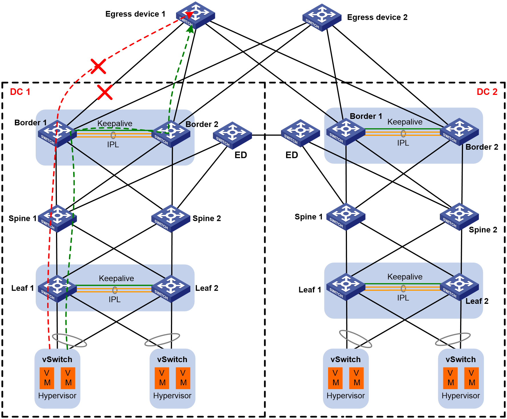
As shown in Figure 7, shut down the outbound interfaces to the external network on both Border 1 and Border 2. The traffic is completely switched to the path marked in green. Border 1 and Border 2 no longer receive the traffic from this group marked in red. On the remote leaf device, you can see that the default static route for this group has been withdrawn. Outbound traffic in the other group and the associated default static route are not affected.
Figure 7 Layer 3 Ethernet interface failure on both border devices
