- Table of Contents
-
- H3C Data Center Switches DRNI Configuration Guide-6W103
- 00-DRNI network planning
- 01-DRNI+IPv4 and IPv6 Dual-Active VLAN Gateway Configuration Example
- 02-Multi-Layer DRNI+STP+Dual-Active VLAN Gateway Configuration Examples
- 03-Multi-Layer DRNI+Dual-Active VLAN Gateway+OSPF Configuration Examples
- 04-Multi-tier DRNI+Spine Gateways+ECMP Paths to External Network Configuration Example
- 05-DRNI and VRRP Configuration Example
- 06-DRNI+RDMA Configuration Example
- 07-DRNI and EVPN Distributed Gateway (IS-IS for underlay routing) Configuration Example
- 08-DRNI and EVPN Distributed Gateway (BGP for Underlay Routing) Configuration Example
- 09-DRNI+EVPN Distributed Gateway (OSPF on Underlay Network)+DHCP Relay+Microsegmentation+Service Chain Configuration Example
- 10-DRNI+EVPN Centralized Gateway Configuration Example
- 11-Access to DRNI Through Dynamic Routing and Distributed EVPN Gateways Configuration Example
- 12-DRNI+EVPN+Monitor Link Configuration Examples
- 13-DRNI and MVXLAN Configuration Example
- 14-DRNI and DCI Configuration Example
- 15-DRNI+EVPN DC Switchover Upon Border Failure Configuration Examples
- Related Documents
-
| Title | Size | Download |
|---|---|---|
| 14-DRNI and DCI Configuration Example | 207.11 KB |
Example: Configuring DRNI and DCI
Configuring EDs in data center 1
Configuring EDs in data center 2
Overlay traffic forwarding models
Overlay traffic characteristics
Testing network convergence upon single points of failure
Example: Configuring DRNI and DCI
Network configuration
As shown in Figure 1:
· The two EDs in each data center (DC) form a DR system. The interfaces connected the EDs in different DCs operate in Layer 3 mode.
· Run a dynamic routing protocol on the EDs. In this example, OSPF is used.
· All the EDs are connected to spine devices.
|
|
NOTE: In this example, the same tenant uses the same VXLAN ID and L3 VXLAN ID for inter-DC communication. |
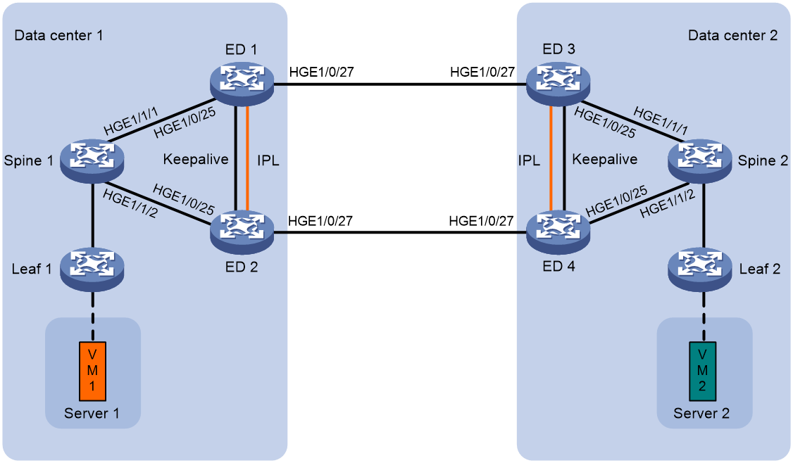
Table 1 Interface and IP address assignment
|
Device |
Interface |
IP address |
|
Spine 1 |
Loopback 0 |
100.1.1.37/32 |
|
HGE 1/1/1 |
Borrowed from Loopback 0 |
|
|
HGE 1/1/2 |
Borrowed from Loopback 0 |
|
|
Spine 2 |
Loopback 0 |
101.1.1.17/32 |
|
HGE 1/1/1 |
Borrowed from Loopback 0 |
|
|
HGE 1/1/2 |
Borrowed from Loopback 0 |
|
|
ED 1 |
Loopback 0 |
100.1.1.47/32 |
|
Loopback 2 |
100.1.1.19/32 |
|
|
HGE 1/0/25 |
Borrowed from Loopback 0 |
|
|
HGE 1/0/27 |
9.1.1.1/24 |
|
|
ED 2 |
Loopback 0 |
100.1.1.48/32 |
|
Loopback 2 |
100.1.1.19/32 |
|
|
HGE 1/0/25 |
Borrowed from Loopback 0 |
|
|
HGE 1/0/27 |
9.1.2.1/24 |
|
|
ED 3 |
Loopback 0 |
101.1.1.26/32 |
|
Loopback 2 |
101.1.1.19/32 |
|
|
HGE 1/0/25 |
Borrowed from Loopback 0 |
|
|
HGE 1/0/27 |
9.1.1.2/24 |
|
|
ED 4 |
Loopback 0 |
101.1.1.27/32 |
|
Loopback 2 |
101.1.1.19/32 |
|
|
HGE 1/0/25 |
Borrowed from Loopback 0 |
|
|
HGE 1/0/27 |
9.1.2.2/24 |
Applicable product matrix
|
|
IMPORTANT: In addition to running an applicable software version, you must also install the most recent patch, if any. |
|
Role |
Device |
Software version |
|
ED |
S6805, S6825, S6850, and S9850 |
F6632 and higher F66xx or R66xx versions |
|
S6800 and S6860 |
F2715 and higher F27xx or R27xx versions |
|
|
S12500X-AF and S6890 |
F2809 and higher F28xx or R28xx versions |
|
|
S12500G-AF |
R7624P12 |
|
|
S9820-64H and S9820-8C |
Not supported |
|
|
S6812 and S6813 |
Not supported |
|
|
SDN controller |
N/A |
E6103 or higher versions NOTE: Before you use a higher version than E6103, contact H3C support to verify version compatibility. |
Restrictions and guidelines
· You must configure the same DR system MAC address for the DR member devices in a DR system and configure different DR system MAC addresses for the DR member devices in different DR systems. Make sure each DR system has a unique DR system MAC address in the network.
· This example covers the settings on the EDs. For more information about configuring the spine and leaf devices, see the configuration guides for the devices.
· Before you perform the tasks in this example, perform the following tasks:
a. Configure IP addresses and masks for interfaces.
b. Configure routing protocols on the transport network to ensure that the devices have routes to reach one another.
· The spine in each DC establishes IBGP peer relationship with the ED and leaf devices in the local DC. The EDs in one DC establish EBGP peer relationship with the EDs in the other DC.
Configuring EDs
Procedure summary
· Configuring EDs in data center 1
· Configuring EDs in data center 2
Configuring EDs in data center 1
|
ED 1 (S6850) |
ED 2 (S6850) |
Configuration method |
Description |
Remarks |
|
drni system-mac 2-2-2 |
drni system-mac 2-2-2 |
Manual or controller-based |
Configure the DR system MAC address. |
For the DR member devices to be identified as one DR system, you must configure the same DR system MAC address on them. |
|
drni system-number 1 |
drni system-number 2 |
Manual or controller-based |
Set the DR system number. |
You must assign different DR system numbers to the DR member devices in a DR system. |
|
drni system-priority 123 |
drni system-priority 123 |
Manual or controller-based |
Set the DR system priority. |
You must configure the same DR system priority for the DR member devices in a DR system. |
|
drni keepalive ip destination 1.0.2.2 source 1.0.2.1 |
drni keepalive ip destination 1.0.2.1 source 1.0.2.2 |
Manual or controller-based |
Specify the destination and source IP addresses of keepalive packets. |
N/A |
|
interface twenty-fivegige 1/0/56 |
interface twenty-fivegige 1/0/56 |
Manual or controller-based |
Enter the view of Twenty-FiveGigE 1/0/56. The interface is attached to the keepalive link. |
N/A |
|
port link-mode route |
port link-mode route |
Manual or controller-based |
Set the link mode of the keepalive interface to Layer 3. |
N/A |
|
ip address 1.0.2.1 24 |
ip address 1.0.2.2 24 |
Manual or controller-based |
Assign an IP address to Twenty-FiveGigE 1/0/56. This IP address is the source IP address of keepalive packets. |
N/A |
|
quit |
quit |
N/A |
N/A |
N/A |
|
drni mad exclude interface twenty-fivegige 1/0/56 |
drni mad exclude interface twenty-fivegige 1/0/56 |
Manual or controller-based |
Exclude Twenty-FiveGigE 1/0/56 from the DRNI MAD shutdown action. |
N/A |
|
vlan 4094 |
vlan 4094 |
Manual or controller-based |
Create VLAN 4094. |
N/A |
|
interface bridge-aggregation 1 |
interface bridge-aggregation 1 |
Manual or controller-based |
Create Layer 2 aggregate interface Bridge-Aggregation 1. This interface will be used as the IPP. |
N/A |
|
link-aggregation mode dynamic |
link-aggregation mode dynamic |
Manual or controller-based |
Configure Bridge-Aggregation 1 to operate in dynamic aggregation mode. |
N/A |
|
quit |
quit |
N/A |
N/A |
N/A |
|
interface range hundredgige 1/0/31 hundredgige 1/0/32 |
interface range hundredgige 1/0/31 hundredgige 1/0/32 |
Manual or controller-based |
Enter the interface range view of physical interfaces that will be assigned to Bridge-Aggregation 1. |
N/A |
|
port link-aggregation group 1 |
port link-aggregation group 1 |
Manual or controller-based |
Assign the physical interfaces to Bridge-Aggregation 1. |
N/A |
|
quit |
quit |
N/A |
N/A |
N/A |
|
interface bridge-aggregation 1 |
interface bridge-aggregation 1 |
Manual or controller-based |
Enter the view of Bridge-Aggregation 1. |
N/A |
|
port drni intra-portal-port 1 |
port drni intra-portal-port 1 |
Manual or controller-based |
Specify Bridge-Aggregation 1 as the IPP. |
N/A |
|
port trunk pvid vlan 4094 |
port trunk pvid vlan 4094 |
Manual or controller-based |
Set the PVID of the IPP to 4094. |
N/A |
|
quit |
quit |
N/A |
N/A |
N/A |
|
interface loopback 0 |
interface loopback 0 |
Manual or controller-based |
Create Loopback 0 and enter its view. |
N/A |
|
ip address 100.1.1.47 32 |
ip address 100.1.1.48 32 |
Manual or controller-based |
Assign an IP address to the interface. |
The IP address must be a local IP address. |
|
interface loopback 2 |
interface loopback 2 |
Manual or controller-based |
Create Loopback 2 and enter its view. |
N/A |
|
ip address 100.1.1.19 32 |
ip address 100.1.1.19 32 |
Manual or controller-based |
Assign an IP address to the interface. |
Specify the virtual VTEP address. |
|
l2vpn enable |
l2vpn enable |
Manual or controller-based |
Enable L2VPN. |
N/A |
|
vxlan tunnel mac-learning disable |
vxlan tunnel mac-learning disable |
Manual or controller-based |
Disable remote-MAC address learning. |
N/A |
|
vxlan tunnel arp-learning disable |
vxlan tunnel arp-learning disable |
Manual or controller-based |
Disable remote ARP learning for VXLANs. |
N/A |
|
vxlan tunnel nd-learning disable |
vxlan tunnel nd-learning disable |
Manual or controller-based |
Disable remote ND learning for VXLANs. |
N/A |
|
vxlan default-decapsulation source interface loopback 0 |
vxlan default-decapsulation source interface loopback 0 |
Manual or controller-based |
Enable default IPv4 VXLAN decapsulation and specify source interface Loopback 0. |
N/A |
|
l2vpn drni peer-link ac-match-rule vxlan-mapping |
l2vpn drni peer-link ac-match-rule vxlan-mapping |
Manual or controller-based |
Enable the switch to create frame match criteria based on VXLAN IDs for the dynamic ACs on the Ethernet aggregate link IPL. |
N/A |
|
ospf 65530 router-id 172.10.1.47 |
ospf 65530 router-id 172.10.1.48 |
Manual or controller-based |
Enable OSPF process 65530 on the underlay network. |
N/A |
|
stub-router include-stub on-startup 900 |
stub-router include-stub on-startup 900 |
Manual or controller-based |
Configure the router as a stub router during reboot and specify the timeout time to 900 seconds. |
N/A |
|
area 0.0.0.0 |
area 0.0.0.0 |
Manual or controller-based |
Create an OSPF area. |
N/A |
|
quit |
quit |
N/A |
N/A |
N/A |
|
interface range loopback 0 loopback 2 |
interface range loopback 0 loopback 2 |
Manual |
Enter the interface range view of Loopback 0 and Loopback 2. |
N/A |
|
ospf 65530 area 0.0.0.0 |
ospf 65530 area 0.0.0.0 |
Manual |
Enable OSPF process 65530 on the loopback interfaces. |
N/A |
|
quit |
quit |
N/A |
N/A |
N/A |
|
Interface hundredgige 1/0/27 |
interface hundredgige 1/0/27 |
Manual |
Enter the view of the DCI interface. A DCI interface is connected to an ED in another DC. |
N/A |
|
port link-type route |
port link-type route |
Manual |
Set the link type of the DCI interface to Layer 3. |
N/A |
|
ip address 9.1.1.1 255.255.255.0 |
ip address 9.1.2.1 255.255.255.0 |
Manual |
Assign an IP address to the DCI interface. |
N/A |
|
ospf 65530 area 0.0.0.0 |
ospf 65530 area 0.0.0.0 |
Manual |
Enable OSPF process 65530 on the DCI interface. |
N/A |
|
ospf peer hold-max-cost duration 60000 |
ospf peer hold-max-cost duration 60000 |
Manual |
On the DCI interface, enable OSPF to advertise the maximum link cost to neighbors within 60 seconds. |
N/A |
|
quit |
quit |
N/A |
N/A |
N/A |
|
evpn drni group 100.1.1.19 |
evpn drni group 100.1.1.19 |
Manual or controller-based |
Enable EVPN distributed relay and specify the virtual VTEP address. |
N/A |
|
ip vpn-instance USERVRF |
ip vpn-instance USERVRF |
Manual or controller-based |
Create VPN instance USERVRF for the service network and enter its view. |
N/A |
|
router-distinguisher 9:10001 |
router-distinguisher 10:10001 |
Manual or controller-based |
Configure an RD for the VPN instance. |
Do not configure the same RD on both the EDs for the VPN instance. |
|
address-family ipv4 |
address-family ipv4 |
Manual or controller-based |
Enter VPN instance IPv4 address family view. |
N/A |
|
vpn-target 0:10001 1:10001 import-extcommunity |
vpn-target 0:10001 1:10001 import-extcommunity |
Manual or controller-based |
Configure the import route targets in VPN instance IPv4 address family view. |
Make sure the same import route targets are configured for the VPN instance on the EDs. |
|
vpn-target 1:10001 export-extcommunity |
vpn-target 1:10001 export-extcommunity |
Manual or controller-based |
Configure the export route targets in VPN instance IPv4 address family view. |
Make sure the same export route targets are configured for the VPN instance on the EDs. |
|
address-family ipv6 |
address-family ipv6 |
Manual or controller-based |
Enter VPN instance IPv6 address family view. |
N/A |
|
vpn-target 0:10001 1:10001 import-extcommunity |
vpn-target 0:10001 1:10001 import-extcommunity |
Manual or controller-based |
Configure the import route targets in VPN instance IPv6 address family view. |
Make sure the same import route targets are configured for the VPN instance on the EDs. |
|
vpn-target 1:10001 export-extcommunity |
vpn-target 1:10001 export-extcommunity |
Manual or controller-based |
Configure the export route targets in VPN instance IPv6 address family view. |
Make sure the same export route targets are configured for the VPN instance on the EDs. |
|
address-family evpn |
address-family evpn |
Manual or controller-based |
Enter VPN instance EVPN view. |
N/A |
|
vpn-target 0:10001 1:10001 import-extcommunity |
vpn-target 0:10001 1:10001 import-extcommunity |
Manual or controller-based |
Configure the import route targets for EVPN. |
Make sure the same import route targets are configured for EVPN on the EDs. |
|
vpn-target 1:10001 export-extcommunity |
vpn-target 1:10001 export-extcommunity |
Manual or controller-based |
Configure the export route targets for EVPN. |
Make sure the same export route targets are configured for EVPN on the EDs. |
|
quit |
quit |
N/A |
N/A |
N/A |
|
quit |
quit |
N/A |
N/A |
N/A |
|
bgp 65530 |
bgp 65530 |
Manual or controller-based |
Create BGP instance 65530. |
N/A |
|
router-id 172.10.1.47 |
router-id 172.10.1.48 |
Manual or controller-based |
Configure a router ID for the BGP instance. |
N/A |
|
group evpn internal |
group evpn internal |
Manual or controller-based |
Create an IBGP peer group named evpn. |
N/A |
|
peer evpn connect-interface loopback 0 |
peer evpn connect-interface loopback 0 |
Manual or controller-based |
Specify source interface Loopback 0 for establishing TCP connections to the peer group. |
N/A |
|
peer 100.1.1.37 group evpn |
peer 100.1.1.37 group evpn |
Manual or controller-based |
Add the spine to peer group evpn. |
N/A |
|
peer 101.1.1.26 as-number 65531 |
peer 101.1.1.26 as-number 65531 |
Manual or controller-based |
Establish EBGP peer relationship with peer ED 3. |
N/A |
|
peer 101.1.1.26 ebgp-max-hop 64 |
peer 101.1.1.26 ebgp-max-hop 64 |
Manual or controller-based |
Enable BGP to establish EBGP sessions to indirectly connected EBGP peer ED 3, and set the maximum hop count to 64. |
N/A |
|
peer 101.1.1.26 source-address 100.1.1.47 |
peer 101.1.1.26 source-address 100.1.1.48 |
Manual or controller-based |
Specify a source IP address for establishing TCP connections to peer ED 3. |
N/A |
|
peer 101.1.1.27 as-number 65531 |
peer 101.1.1.27 as-number 65531 |
Manual or controller-based |
Establish EBGP peer relationship with peer ED 4. |
N/A |
|
peer 101.1.1.27 ebgp-mac-hop 64 |
peer 101.1.1.27 ebgp-mac-hop 64 |
Manual or controller-based |
Enable BGP to establish EBGP sessions to indirectly connected EBGP peer ED 4, and set the maximum hop count to 64. |
N/A |
|
peer 101.1.1.27 source-address 100.1.1.47 |
peer 101.1.1.27 source-address 100.1.1.48 |
Manual or controller-based |
Specify a source IP address for establishing TCP connections to peer ED 4. |
N/A |
|
address-family l2vpn evpn |
address-family l2vpn evpn |
Manual or controller-based |
Enter BGP EVPN address family view. |
N/A |
|
nexthop evpn-drni group-address |
nexthop evpn-drni group-address |
Manual or controller-based |
Enable the switch to replace the next hop in advertised BGP EVPN routes with the virtual VTEP address. |
N/A |
|
peer evpn enable |
peer evpn enable |
Manual or controller-based |
Enable BGP to exchange unicast routing information with peer group evpn. |
N/A |
|
peer 100.1.1.37 next-hop-local |
peer 100.1.1.37 next-hop-local |
Manual or controller-based |
Set the local router as the next hop for routes sent to peer 100.1.1.37. |
N/A |
|
peer 101.1.1.26 enable |
peer 101.1.1.26 enable |
Manual or controller-based |
Enable BGP to exchange unicast routing information with peer 101.1.1.26. |
N/A |
|
peer 101.1.1.26 router-mac-local dci |
peer 101.1.1.26 router-mac-local dci |
Manual or controller-based |
Enable the switch to use its router MAC address to replace the router MAC address of routes received from and advertised to peer 101.1.1.26 and establish VXLAN-DCI tunnels with the peer. |
N/A |
|
peer 101.1.1.27 enable |
peer 101.1.1.27 enable |
Manual or controller-based |
Enable BGP to exchange unicast routing information with peer 101.1.1.27. |
N/A |
|
peer 101.1.1.27 router-mac-local dci |
peer 101.1.1.27 router-mac-local dci |
Manual or controller-based |
Enable the switch to use its router MAC address to replace the router MAC address of routes received from and advertised to peer 101.1.1.27 and establish VXLAN-DCI tunnels with the peer. |
N/A |
|
quit |
quit |
N/A |
N/A |
N/A |
|
quit |
quit |
N/A |
N/A |
N/A |
|
interface vlan-interface 4094 |
interface vlan-interface 4094 |
Manual or controller-based |
Create VLAN-interface 4094. |
N/A |
|
ip address 100.1.1.70 255.255.255.252 |
ip address 100.1.1.69 255.255.255.252 |
Manual or controller-based |
Assign an IP address to the VLAN interface. |
N/A |
|
ospf 65530 area 0.0.0.0 |
ospf 65530 area 0.0.0.0 |
Manual or controller-based |
Enable OSPF process 65530. |
N/A |
|
ospf peer hold-max-cost duration 60000 |
ospf peer hold-max-cost duration 60000 |
Manual |
On the VLAN interface, enable OSPF to advertise the maximum link cost to neighbors within 60 seconds. |
N/A |
|
quit |
quit |
N/A |
N/A |
N/A |
Configuring EDs in data center 2
|
ED 3 (S6850) |
ED 4 (S6850) |
Configuration method |
Description |
Remarks |
|
drni system-mac 3-3-3 |
drni system-mac 3-3-3 |
Manual or controller-based |
Configure the DR system MAC address. |
For the DR member devices to be identified as one DR system, you must configure the same DR system MAC address on them. |
|
drni system-number 1 |
drni system-number 2 |
Manual or controller-based |
Set the DR system number. |
You must assign different DR system numbers to the DR member devices in a DR system. |
|
drni system-priority 123 |
drni system-priority 123 |
Manual or controller-based |
Set the DR system priority. |
You must configure the same DR system priority for the DR member devices in a DR system. |
|
drni keepalive ip destination 1.0.3.2 source 1.0.3.1 |
drni keepalive ip destination 1.0.3.1 source 1.0.3.2 |
Manual or controller-based |
Specify the destination and source IP addresses of keepalive packets. |
N/A |
|
interface twenty-fivegige 1/0/56 |
interface twenty-fivegige 1/0/56 |
Manual or controller-based |
Enter the view of Twenty-FiveGigE 1/0/56. The interface is attached to the keepalive link. |
N/A |
|
port link-mode route |
port link-mode route |
Manual or controller-based |
Set the link mode of the keepalive interface to Layer 3. |
N/A |
|
ip address 1.0.3.1 24 |
ip address 1.0.3.2 24 |
Manual or controller-based |
Assign an IP address to Twenty-FiveGigE 1/0/56. This IP address is the source IP address of keepalive packets. |
N/A |
|
quit |
quit |
N/A |
N/A |
N/A |
|
drni mad exclude interface twenty-fivegige 1/0/56 |
drni mad exclude interface twenty-fivegige 1/0/56 |
Manual or controller-based |
Exclude Twenty-FiveGigE 1/0/56 from the DRNI MAD shutdown action. |
N/A |
|
vlan 4094 |
vlan 4094 |
Manual or controller-based |
Create VLAN 4094. |
N/A |
|
interface bridge-aggregation 1 |
interface bridge-aggregation 1 |
Manual or controller-based |
Create Layer 2 aggregate interface Bridge-Aggregation 1. This interface will be used as the IPP. |
N/A |
|
link-aggregation mode dynamic |
link-aggregation mode dynamic |
Manual or controller-based |
Configure Bridge-Aggregation 1 to operate in dynamic aggregation mode. |
N/A |
|
quit |
quit |
N/A |
N/A |
N/A |
|
interface range hundredgige 1/0/31 hundredgige 1/0/32 |
interface range hundredgige 1/0/31 hundredgige 1/0/32 |
Manual or controller-based |
Enter the interface range view of the physical interfaces that will be assigned to Bridge-Aggregation 1. |
N/A |
|
port link-aggregation group 1 |
port link-aggregation group 1 |
Manual or controller-based |
Assign the physical interfaces to Bridge-Aggregation 1. |
N/A |
|
quit |
quit |
N/A |
N/A |
N/A |
|
interface bridge-aggregation 1 |
interface bridge-aggregation 1 |
Manual or controller-based |
Enter the view of Bridge-Aggregation 1.. |
N/A |
|
port drni intra-portal-port 1 |
port drni intra-portal-port 1 |
Manual or controller-based |
Specify Bridge-Aggregation 1 as the IPP. |
N/A |
|
port trunk pvid vlan 4094 |
port trunk pvid vlan 4094 |
Manual or controller-based |
Set the PVID of the IPP to 4094. |
N/A |
|
quit |
quit |
N/A |
N/A |
N/A |
|
interface loopback 0 |
interface loopback 0 |
Manual or controller-based |
Create Loopback 0 and enter its view. |
N/A |
|
ip address 101.1.1.26 32 |
ip address 101.1.1.27 32 |
Manual or controller-based |
Assign an IP address to the interface. |
The IP address must be a local IP address. |
|
interface loopback 2 |
interface loopback 2 |
Manual or controller-based |
Create Loopback 2 and enter its view. |
N/A |
|
ip address 101.1.1.19 32 |
ip address 101.1.1.19 32 |
Manual or controller-based |
Assign an IP address to the interface. |
Specify the virtual VTEP address. |
|
l2vpn enable |
l2vpn enable |
Manual or controller-based |
Enable L2VPN. |
N/A |
|
vxlan tunnel mac-learning disable |
vxlan tunnel mac-learning disable |
Manual or controller-based |
Disable remote-MAC address learning. |
N/A |
|
vxlan tunnel arp-learning disable |
vxlan tunnel arp-learning disable |
Manual or controller-based |
Disable remote ARP learning for VXLANs. |
N/A |
|
vxlan tunnel nd-learning disable |
vxlan tunnel nd-learning disable |
Manual or controller-based |
Disable remote ND learning for VXLANs. |
N/A |
|
vxlan default-decapsulation source interface loopback 0 |
vxlan default-decapsulation source interface loopback 0 |
Manual or controller-based |
Enable default IPv4 VXLAN decapsulation and specify source interface Loopback 0. |
N/A |
|
l2vpn drni peer-link ac-match-rule vxlan-mapping |
l2vpn drni peer-link ac-match-rule vxlan-mapping |
Manual or controller-based |
Enable the switch to create frame match criteria based on VXLAN IDs for the dynamic ACs on the Ethernet aggregate link IPL. |
N/A |
|
ospf 65531 router-id 172.10.2.27 |
ospf 65531 router-id 172.10.2.26 |
Manual or controller-based |
Enable OSPF process 65531 on the underlay network. |
N/A |
|
stub-router include-stub on-startup 900 |
stub-router include-stub on-startup 900 |
Manual |
Configure the router as a stub router during reboot and specify the timeout time to 900 seconds. |
N/A |
|
area 0.0.0.0 |
area 0.0.0.0 |
Manual or controller-based |
Create an OSPF area. |
N/A |
|
quit |
quit |
N/A |
N/A |
N/A |
|
interface range loopback 0 loopback 2 |
interface range loopback 0 loopback 2 |
Manual |
Enter the interface range of Loopback 0 and Loopback 2. |
N/A |
|
ospf 65531 area 0.0.0.0 |
ospf 65531 area 0.0.0.0 |
Manual |
Enable OSPF process 65531 on the interfaces. |
N/A |
|
quit |
quit |
N/A |
N/A |
N/A |
|
Interface hundredgige 1/0/27 |
interface hundredgige 1/0/27 |
Manual |
Enter the view of the DCI interface. A DCI interface is connected to an ED in another DC. |
N/A |
|
port link-type route |
port link-type route |
Manual |
Set the link type of the DCI interface to Layer 3. |
N/A |
|
ip address 9.1.1.2 255.255.255.0 |
ip address 9.1.2.2 255.255.255.0 |
Manual |
Assign an IP address to the DCI interface. |
N/A |
|
ospf 65531 area 0.0.0.0 |
ospf 65531 area 0.0.0.0 |
Manual |
Enable OSPF process 65531 on the DCI interface. |
N/A |
|
ospf peer hold-max-cost duration 60000 |
ospf peer hold-max-cost duration 60000 |
Manual |
On the DCI interface, enable OSPF to advertise the maximum link cost to neighbors within 60 seconds. |
N/A |
|
quit |
quit |
N/A |
N/A |
N/A |
|
evpn drni group 101.1.1.19 |
evpn drni group 101.1.1.19 |
Manual or controller-based |
Enable EVPN distributed relay and specify the virtual VTEP address. |
N/A |
|
ip vpn-instance USERVRF |
ip vpn-instance USERVRF |
Manual or controller-based |
Create VPN instance USERVRF for the service network and enter its view. |
N/A |
|
router-distinguisher 11:10001 |
router-distinguisher 12:10001 |
Manual or controller-based |
Configure an RD for the VPN instance. |
Do not configure the same RD for the VPN instance on the EDs. |
|
address-family ipv4 |
address-family ipv4 |
Manual or controller-based |
Enter VPN instance IPv4 address family view. |
N/A |
|
vpn-target 0:10001 1:10001 import-extcommunity |
vpn-target 0:10001 1:10001 import-extcommunity |
Manual or controller-based |
Configure the import route targets in VPN instance IPv4 address family view. |
Make sure the same import route targets are configured for the VPN instance on the EDs. |
|
vpn-target 1:10001 export-extcommunity |
vpn-target 1:10001 export-extcommunity |
Manual or controller-based |
Configure the export route targets in VPN instance IPv4 address family view. |
Make sure the same export route targets are configured for the VPN instance on the EDs. |
|
address-family ipv6 |
address-family ipv6 |
Manual or controller-based |
Enter VPN instance IPv6 address family view. |
N/A |
|
vpn-target 0:10001 1:10001 import-extcommunity |
vpn-target 0:10001 1:10001 import-extcommunity |
Manual or controller-based |
Configure the import route targets in VPN instance IPv6 address family view. |
Make sure the same import route targets are configured for the VPN instance on the EDs. |
|
vpn-target 1:10001 export-extcommunity |
vpn-target 1:10001 export-extcommunity |
Manual or controller-based |
Configure the export route targets in VPN instance IPv6 address family view. |
Make sure the same export route targets are configured for the VPN instance on the EDs. |
|
address-family evpn |
address-family evpn |
Manual or controller-based |
Enter VPN instance EVPN view. |
N/A |
|
vpn-target 0:10001 1:10001 import-extcommunity |
vpn-target 0:10001 1:10001 import-extcommunity |
Manual or controller-based |
Configure the import route targets for EVPN. |
Make sure the same import route targets are configured for EVPN on the EDs. |
|
vpn-target 1:10001 export-extcommunity |
vpn-target 1:10001 export-extcommunity |
Manual or controller-based |
Configure the export route targets for EVPN. |
Make sure the same export route targets are configured for EVPN on the EDs. |
|
quit |
quit |
N/A |
N/A |
N/A |
|
quit |
quit |
N/A |
N/A |
N/A |
|
bgp 65531 |
bgp 65531 |
Manual or controller-based |
Create BGP instance 65531. |
N/A |
|
router-id 172.10.2.27 |
router-id 172.10.2.26 |
Manual or controller-based |
Configure a router ID for the BGP instance. |
N/A |
|
group evpn internal |
group evpn internal |
Manual or controller-based |
Create an IBGP peer group named evpn. |
N/A |
|
peer evpn connect-interface loopback 0 |
peer evpn connect-interface loopback 0 |
Manual or controller-based |
Specify source interface Loopback 0 for establishing TCP connections to the peer group. |
N/A |
|
peer 101.1.1.17 group evpn |
peer 101.1.1.17 group evpn |
Manual or controller-based |
Add the spine to peer group evpn. |
N/A |
|
peer 100.1.1.47 as-number 65530 |
peer 100.1.1.47 as-number 65530 |
Manual or controller-based |
Establish EBGP peer relationship with peer ED 1. |
N/A |
|
peer 100.1.1.47 ebgp-max-hop 64 |
peer 100.1.1.47 ebgp-max-hop 64 |
Manual or controller-based |
Enable BGP to establish EBGP sessions to indirectly connected EBGP peer ED 1, and set the maximum hop count to 64. |
N/A |
|
peer 100.1.1.47 source-address 101.1.1.26 |
peer 100.1.1.47 source-address 101.1.1.27 |
Manual or controller-based |
Specify a source IPv4 address for establishing TCP connections to peer ED 1. |
N/A |
|
peer 100.1.1.48 as-number 65530 |
peer 100.1.1.48 as-number 65530 |
Manual or controller-based |
Establish EBGP peer relationship with peer ED 2. |
N/A |
|
peer 100.1.1.48 ebgp-mac-hop 64 |
peer 100.1.1.48 ebgp-mac-hop 64 |
Manual or controller-based |
Enable BGP to establish EBGP sessions to indirectly connected EBGP peer ED 2, and set the maximum hop count to 64. |
N/A |
|
peer 100.1.1.48 source-address 101.1.1.26 |
peer 100.1.1.48 source-address 101.1.1.27 |
Manual or controller-based |
Specify a source IPv4 address for establishing TCP connections to peer ED 2. |
N/A |
|
address-family l2vpn evpn |
address-family l2vpn evpn |
Manual or controller-based |
Enter BGP EVPN address family view. |
N/A |
|
nexthop evpn-drni group-address |
nexthop evpn-drni group-address |
Manual or controller-based |
Enable the switch to replace the next hop in advertised BGP EVPN routes with the virtual VTEP address. |
N/A |
|
peer evpn enable |
peer evpn enable |
Manual or controller-based |
Enable BGP to exchange unicast routing information with peer group evpn. |
N/A |
|
peer 101.1.1.17 next-hop-local |
peer 101.1.1.17 next-hop-local |
Manual or controller-based |
Set the local router as the next hop for routes sent to peer 101.1.1.17. |
N/A |
|
peer 100.1.1.47 enable |
peer 100.1.1.47 enable |
Manual or controller-based |
Enable BGP to exchange unicast routing information with peer 100.1.1.47. |
N/A |
|
peer 100.1.1.47 router-mac-local dci |
peer 100.1.1.47 router-mac-local dci |
Manual or controller-based |
Enable the switch to use its router MAC address to replace the router MAC address of routes received from and advertised to peer 100.1.1.47 and establish VXLAN-DCI tunnels with the peer. |
N/A |
|
peer 100.1.1.48 enable |
peer 100.1.1.48 enable |
Manual or controller-based |
Enable BGP to exchange unicast routing information with peer 100.1.1.48. |
N/A |
|
peer 100.1.1.48 router-mac-local dci |
peer 100.1.1.48 router-mac-local dci |
Manual or controller-based |
Enable the switch to use its router MAC address to replace the router MAC address of routes received from and advertised to peer 100.1.1.48 and establish VXLAN-DCI tunnels with the peer. |
N/A |
|
quit |
quit |
N/A |
N/A |
N/A |
|
quit |
quit |
N/A |
N/A |
N/A |
|
interface vlan-interface 4094 |
interface vlan-interface 4094 |
Manual or controller-based |
Create VLAN-interface 4094. |
N/A |
|
ip address 101.1.1.29 255.255.255.252 |
ip address 101.1.1.30 255.255.255.252 |
Manual or controller-based |
Assign an IP address to VLAN-interface 4094. |
N/A |
|
ospf 65531 area 0.0.0.0 |
ospf 65531 area 0.0.0.0 |
Manual or controller-based |
Enable OSPF process 65531. |
N/A |
|
ospf peer hold-max-cost duration 60000 |
ospf peer hold-max-cost duration 60000 |
Manual |
On the VLAN interface, enable OSPF to advertise the maximum link cost to neighbors within 60 seconds. |
N/A |
|
quit |
quit |
N/A |
N/A |
N/A |
Overlay traffic forwarding models
Overlay traffic characteristics
The following table describes overlay traffic characteristics:
|
Parameter |
Description |
|
No. |
Overlay traffic number in the format of xxx, starting from 001. |
|
Traffic type |
Traffic type, which is IPv4 or IPv6 known unicast. |
|
Direction |
Traffic direction. Traffic can be forwarded from south to north across EDs or from north to south across EDs. |
|
Forwarding path |
List of nodes that the traffic passes through. |
|
Traffic simulation |
Simulation method used in the test. A tester is simulated as a server to transmit traffic. The following types of traffic is injected: · Server A sends 10K ARP or ND request traffic to Server B. · Server B replies to the ARP or ND request traffic of Server A. The traffic amount is also 10K. · Traffic is sent between the servers and between the servers and the external network. The source port of each flow changes 100th times. · 20K traffic is sent from each server to the external network through the border. |
|
Load |
Traffic load is light or heavy. If the number of flows is less than 1000, the load is light. If the number of flows is more than 1000, the load is heavy. |
|
Traffic direction to firewalls/LB |
Enter the method used to direct traffic to firewalls or LBs. In this example, no firewalls or LBs are deployed. |
Forwarding models
|
No. |
Traffic type |
Direction |
Forwarding path |
Traffic simulation |
Load |
Traffic direction to firewalls/LB |
|
001 |
Known unicast/IPv4 |
DC 1 to DC 2 |
Server 1 > Leaf 1 > Spine 1 > ED 1 & ED 2 > ED 3 & ED 4 > Spine 2 > Leaf 2 > Server 2 |
Tester |
Light |
N/A |
|
002 |
Known unicast/IPv6 |
DC 1 to DC 2 |
Server 1 > Leaf 1 > Spine 1 > ED 1 & ED 2 > ED 3 & ED 4 > Spine 2 > Leaf 2 > Server 2 |
Tester |
Light |
N/A |
|
003 |
Known unicast/IPv4 |
DC 2 to DC 1 |
Server 2 > Leaf 2 > Spine 2 > ED 3 & ED 4 > ED 1 & ED 2 > Spine 1 > Leaf 1 > Server 1 |
Tester |
Light |
N/A |
|
004 |
Known unicast/IPv6 |
DC 2 to DC 1 |
Server 2 > Leaf 2 > Spine 2 > ED 3 & ED 4 > ED 1 & ED 2 > Spine 1 > Leaf 1 > Server 1 |
Tester |
Light |
N/A |
Testing network convergence upon single points of failure
Table 2 Network convergence upon single points of failure
|
Device |
Failure type |
Traffic interruption time |
|
ED |
Link failure when the traffic load is light. |
≤ 500 ms |
|
Link failure recovery when the traffic load is light. |
≤ 150 ms |
|
|
Node failure when the traffic load is light. |
≤ 500 ms |
|
|
Node failure recovery when the traffic load is light. |
≤ 150 ms |
|
|
IMPORTANT: On EDs, use the ospf peer hold-max-cost duration 60000 command on the Layer 3 interfaces connected to spine devices. This configuration ensures fast network convergence upon single points of failure for nodes. |
Verifying the configuration
Verification commands
|
ED |
Description |
|
display drni summary |
Displays summary information about the IPP and DR interfaces. |
|
display drni keepalive |
Displays DR keepalive packet statistics. |
|
display drni role |
Displays DR role information. |
|
display drni system |
Displays the DR system settings. |
|
display bgp peer l2vpn evpn |
Displays BGP EVPN peers or peer groups. |
Procedure
This following information uses ED 1 as an example to verify that the EDs have established DR systems and the DR systems are running correctly.
# Display summary information about the IPP and DR interfaces.
[ED1] display drni summary
Flags: A -- Aggregate interface down, B -- No peer DR interface configured
C -- Configuration consistency check failed
IPP: BAGG1
IPP state (cause): UP
Keepalive link state (cause): UP
# Display DR keepalive packet statistics.
[ED1] display drni keepalive
Neighbor keepalive link status (cause): Up
Neighbor is alive for: 1471174 s 136 ms
Keepalive packet transmission status:
Sent: Successful
Received: Successful
Last received keepalive packet information:
Source IP address: 100.1.1.53
Time: 2021/10/28 11:42:21
Action: Accept
Distributed relay keepalive parameters:
Destination IP address: 100.1.1.53
Source IP address: 100.1.1.54
Keepalive UDP port : 6400
Keepalive VPN name : auto-online-mlag
Keepalive interval : 1000 ms
Keepalive timeout : 5 sec
Keepalive hold time: 3 sec
# Display DR role information.
[ED1] display drni role
Effective role information
Factors Local Peer
Effective role Secondary Primary
Initial role None Primary
MAD DOWN state No No
Health level 0 0
Role priority 32768 32768
Bridge MAC 5cc9-995f-cb8a 0440-a9b8-52c9
Effective role trigger: IPL calculation
Effective role reason: Single None role
Configured role information
Factors Local Peer
Configured role Secondary Primary
Role priority 32768 32768
Bridge MAC 5cc9-995f-cb8a 0440-a9b8-52c9
# Display the DR system settings.
[ED1] display drni system
System information
Local system number: 2 Peer system number: 1
Local system MAC: 5cc9-995f-cb8a Peer system MAC: 5cc9-995f-cb8a
Local system priority: 10 Peer system priority: 10
Local bridge MAC: 5cc9-995f-cb8a Peer bridge MAC: 0440-a9b8-52c9
Local effective role: Secondary Peer effective role: Primary
Health level: 0
Standalone mode on split: Disabled
In standalone mode: No
System timer information
Timer State Value (s) Remaining time (s)
Auto recovery Disabled - -
Restore delay Disabled 180 -
Consistency-check delay Disabled 90 -
Standalone delay Disabled - -
Role to None delay Disabled 60 -
# Verify that ED 1 has established EBGP peer relationship with ED 3, ED 4, and Spine 1.
[ED1] display bgp peer l2vpn evpn
BGP local router ID: 172.10.1.47
Local AS number: 65530
Total number of peers: 3 Peers in established state: 3
* - Dynamically created peer
^ - Peer created through link-local address
Peer AS MsgRcvd MsgSent OutQ PrefRcv Up/Down State
100.1.1.37 65530 801329 1038226 0 681 0410h40m Established
101.1.1.26 65531 485 313 0 480 03:06:56 Established
101.1.1.27 65531 465 301 0 456 03:05:35 Established
Upgrading the devices
Upgrading an ED
Checking the environment
Execute the commands in "Verification commands" and the following commands to verify that the ED is available for an upgrade.
|
ED |
Description |
|
display device |
Displays device information. |
|
display boot-loader |
Displays current software images and startup software images. |
|
display version |
Displays system version information. |
Upgrading the ED
See H3C Switches DR System Upgrade & Replacement & Expansion Guide.
Verifying the traffic interruption time during the upgrade
Verify that the traffic interruption time is shorter than 500 ms during a switchover and shorter than 150 ms during fallback when the traffic load is light. For more information, see "Testing network convergence upon single points of failure."
Verifying the upgrade result
Execute the commands in "Verification commands" and the following commands to verify that the ED is upgraded successfully.
|
ED |
Description |
|
display device |
Displays device information. |
|
display boot-loader |
Displays current software images and startup software images. |
|
display version |
Displays system version information. |
Replacing hardware
Replacing a service module
Checking the environment
Execute the commands in "Verification commands" and the following commands to verify that the target ED is available for a replacement.
|
ED |
Description |
|
display device |
Displays device information. |
|
display boot-loader |
Displays current software images and startup software images. |
|
display version |
Displays system version information. |
Replacing a service module
1. Switch service and management traffic on the target service module to other service modules.
2. Power off the ED and replace the service module, or replace the service module when the ED is running. For more information, see the installation guides for the service module.
For details, see H3C Switches DR System Upgrade & Replacement & Expansion Guide.
Verifying the traffic interruption time
For more information, see "Testing network convergence upon single points of failure."
Verifying the replacement result
Execute the commands in "Checking the environment."
Replacing a switching fabric module
Checking the environment
Execute the commands in "Verification commands" and the following commands to verify that the target ED is available for a replacement.
|
ED |
Description |
|
display device |
Displays device information. |
|
display boot-loader |
Displays current software images and startup software images. |
|
display version |
Displays system version information. |
Replacing a switching fabric module
Power off the ED and replace the switching fabric module, or replace the switching fabric module when the ED is running. For more information, see the installation guides for the switching fabric module.
Verifying the traffic interruption time
For more information, see "Testing network convergence upon single points of failure."
Verifying the replacement result
Execute the commands in "Checking the environment."
Replacing an ED
Checking the environment
Execute the commands in "Verification commands" and the following commands to verify that the target ED is available for a replacement.
|
ED |
Description |
|
display device |
Displays device information. |
|
display boot-loader |
Displays current software images and startup software images. |
|
display version |
Displays system version information. |
Replacing an ED
See H3C Switches DR System Upgrade & Replacement & Expansion Guide.
Verifying the traffic interruption time
For more information, see "Testing network convergence upon single points of failure."
Verifying the replacement result
Execute the commands in "Checking the environment."