- Table of Contents
-
- H3C Data Center Switches DRNI Configuration Guide-6W103
- 00-DRNI network planning
- 01-DRNI+IPv4 and IPv6 Dual-Active VLAN Gateway Configuration Example
- 02-Multi-Layer DRNI+STP+Dual-Active VLAN Gateway Configuration Examples
- 03-Multi-Layer DRNI+Dual-Active VLAN Gateway+OSPF Configuration Examples
- 04-Multi-tier DRNI+Spine Gateways+ECMP Paths to External Network Configuration Example
- 05-DRNI and VRRP Configuration Example
- 06-DRNI+RDMA Configuration Example
- 07-DRNI and EVPN Distributed Gateway (IS-IS for underlay routing) Configuration Example
- 08-DRNI and EVPN Distributed Gateway (BGP for Underlay Routing) Configuration Example
- 09-DRNI+EVPN Distributed Gateway (OSPF on Underlay Network)+DHCP Relay+Microsegmentation+Service Chain Configuration Example
- 10-DRNI+EVPN Centralized Gateway Configuration Example
- 11-Access to DRNI Through Dynamic Routing and Distributed EVPN Gateways Configuration Example
- 12-DRNI+EVPN+Monitor Link Configuration Examples
- 13-DRNI and MVXLAN Configuration Example
- 14-DRNI and DCI Configuration Example
- 15-DRNI+EVPN DC Switchover Upon Border Failure Configuration Examples
- Related Documents
-
| Title | Size | Download |
|---|---|---|
| 11-Access to DRNI Through Dynamic Routing and Distributed EVPN Gateways Configuration Example | 366.92 KB |
Example: Access to DRNI Through Dynamic Routing and Distributed EVPN Gateways Configuration Example
Example: Access to DRNI Through Dynamic Routing and Distributed EVPN Gateways Configuration Example
Network configuration
As shown in Figure 1:
· Leaf 1 and Leaf 2 are distributed EVPN gateways that are virtualized into one DR system. The IPL is an Ethernet aggregate link.
· Spine 1 and Spine 2 act as RRs to reflect routes between the leaf devices and between the leaf and border devices.
· Switch A and Switch B each is dual-homed to Leaf 1 and Leaf 2 through an Ethernet aggregate link. To avoid single points of failure, a Layer 2 Ethernet interface that contains member ports across devices is configured for the links connected to each VM.
· Standalone device Leaf 3 is connected to Switch C through a Layer 2 aggregate link.
· Switch D and Switch E each is single-homed to Leaf 1 and Leaf 2 through a physical link.
· To forward VXLAN traffic from one DR member to the other DR member for single-homed ACs, the DR member devices create VXLAN tunnels over the IPL.
· For Layer 3 communication, enable a routing protocol for route advertisement between Leaf 1 and Leaf 2 and the user network. The underlay network is an IPv4 network and the overlay network is an IPv4 and IPv6 network.
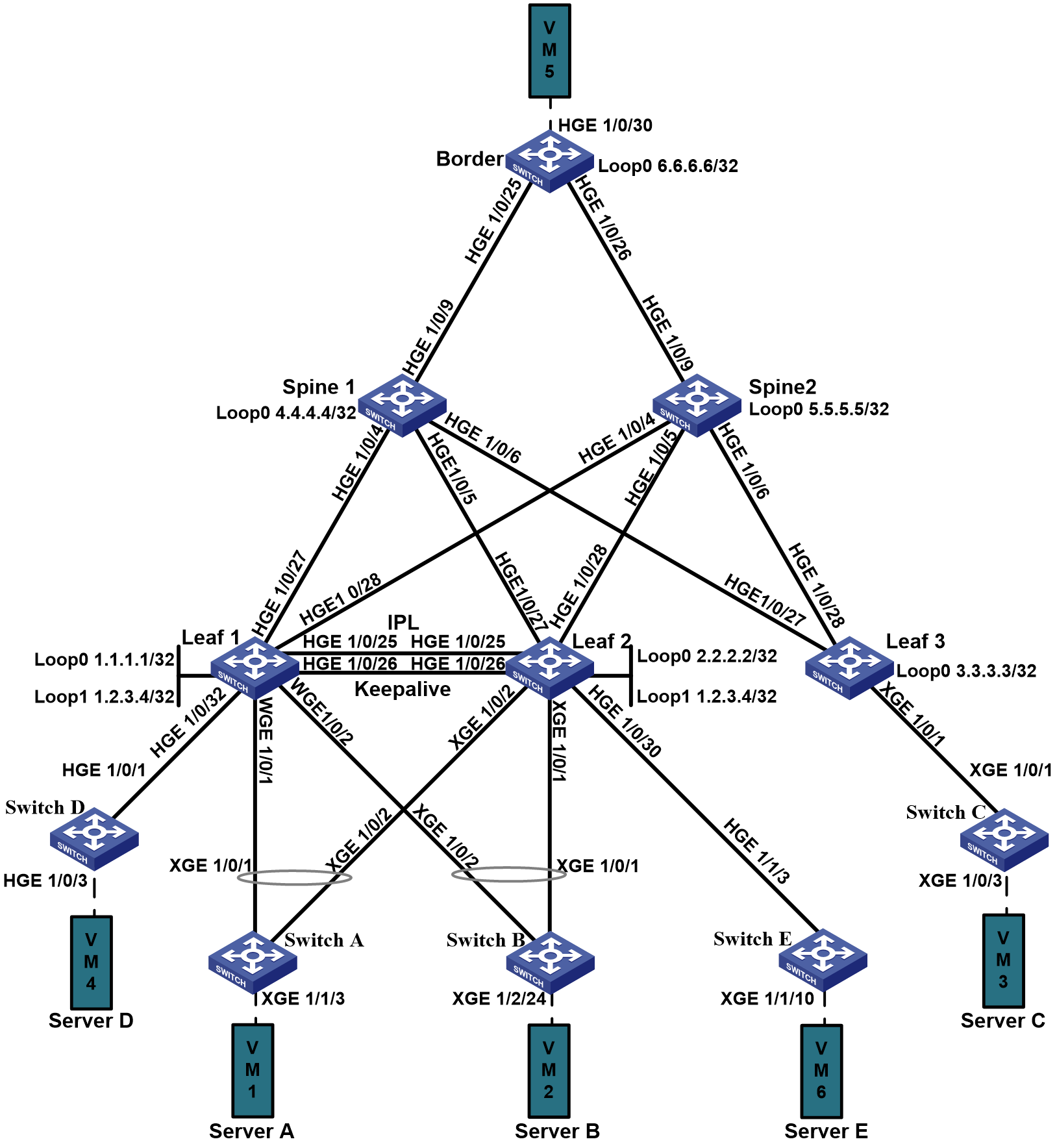
Table 1 Topology and IP assignment
|
Device |
Interface |
IP address |
Remarks |
|
Leaf 1 |
Loopback 0 |
1.1.1.1/32 |
VTEP address Used to establish BGP EVPN peer relationship |
|
Loopback 1 |
1.2.3.4/32 |
Virtual VTEP address |
|
|
VLAN-interface 4094 |
100.0.1.1/24 |
Attached to the link that forwards east-west traffic |
|
|
HGE 1/0/25 |
N/A |
Attached to the IPL Connected to HGE 1/0/25 on Leaf 2 |
|
|
HGE 1/0/26 |
100.0.0.1/24 100::1/64 |
Attached to the keepalive link Connected to HGE 1/0/26 on Leaf 2. |
|
|
HGE 1/0/27 |
Borrowed from Loopback 0 |
Connected to HGE 1/0/4 on Spine 1. |
|
|
HGE 1/0/28 |
Borrowed from Loopback 0 |
Connected to HGE 1/0/4 on Spine 2. |
|
|
HGE 1/0/32 |
N/A |
AC interface Connected to HGE 1/0/1 on Switch D |
|
|
WGE 1/0/1 |
N/A |
DR group member port Connected to Server A |
|
|
WGE 1/0/2 |
N/A |
DR group member port Connected to Server B |
|
|
VSI-interface 10 |
20.1.1.1/24 20:1:1:1::1/64 Virtual IP: 20.1.1.5/24 IPv6 virtual IP: 20:1:1:1::5/64 |
Gateway interface for VXLAN 100 |
|
|
VSI-interface 20 |
20.2.1.1/24 20:2:1:1::1/64 Virtual IP: 20.2.1.5/24 IPv6 virtual IP: 20:2:1:1::5/64 |
Gateway interface for VXLAN 101 |
|
|
VSI-interface 100 |
N/A |
Associated with a L3 VXLAN ID |
|
|
Leaf 2 |
Loopback 0 |
2.2.2.2/32 |
VTEP address Used to establish BGP EVPN peer relationship |
|
Loopback 1 |
1.2.3.4/32 |
Virtual VTEP address |
|
|
VLAN-interface 4094 |
100.0.1.2/24 |
Attached to the link that forwards east-west traffic |
|
|
HGE 1/0/25 |
N/A |
Attached to the IPL Connected to HGE 1/0/25 on Leaf 1 |
|
|
HGE 1/0/26 |
100.0.0.2/24 100::2/64 |
Attached to the keepalive link Connected to HGE 1/0/26 on Leaf 1 |
|
|
HGE 1/0/27 |
N/A |
Borrowed from Loopback 0 Connected to HGE 1/0/5 on Spine 1 |
|
|
HGE 1/0/28 |
N/A |
Borrowed from Loopback 0 Connected to HGE 1/0/5 on Spine 2 |
|
|
HGE 1/0/30 |
N/A |
Single-homed AC interface Connected to HGE 1/1/3 on Switch E |
|
|
XGE 1/0/1 |
N/A |
DR group member port Connected to Server B |
|
|
XGE 1/0/2 |
N/A |
DR group member port Connected to Server A |
|
|
VSI-interface 10 |
20.1.1.1/24 20:1:1:1::1/64 Virtual IP: 20.1.1.6/24 IPv6 virtual IP: 20:1:1:1::6/64 |
Gateway interface for VXLAN 100 |
|
|
VSI-interface 20 |
20.2.1.1/24 20:2:1:1::1/64 Virtual IP: 20.2.1.6/24 IPv6 virtual IP: 20:2:1:1::6/64 |
Gateway interface for VXLAN 101 |
|
|
VSI-interface 100 |
N/A |
Associated with a L3 VXLAN ID |
|
|
Leaf 3 |
Loopback 0 |
3.3.3.3/32 |
VTEP address Used to establish BGP EVPN peer relationship |
|
HGE 1/0/27 |
Borrowed from Loopback 0 |
Connected to HGE 1/0/6 on Spine 1 |
|
|
HGE 1/0/28 |
Borrowed from Loopback 0 |
Connected to HGE 1/0/6 on Spine 2 |
|
|
XGE 1/0/1 |
N/A |
Member port of a Layer 2 aggregate interface Connected to Server 3 |
|
|
Spine 1 |
Loopback 0 |
4.4.4.4/32 |
VTEP address Used to establish BGP EVPN peer relationship |
|
HGE 1/0/4 |
N/A |
Borrowed from Loopback 0 Connected to HGE 1/0/27 on Leaf 1 |
|
|
HGE 1/0/5 |
N/A |
Borrowed from Loopback 0 Connected to HGE 1/0/27 on Leaf 2 |
|
|
HGE 1/0/6 |
N/A |
Borrowed from Loopback 0 Connected to HGE 1/0/27 on Leaf 3 |
|
|
HGE 1/0/9 |
30.0.0.1/24 |
Connected to HGE 1/0/25 on the border device |
|
|
Spine 2 |
Loopback 0 |
5.5.5.5/32 |
VTEP address Used to establish BGP EVPN peer relationship |
|
HGE 1/0/4 |
N/A |
Borrowed from Loopback 0 Connected to HGE 1/0/28 on Leaf 1 |
|
|
HGE 1/0/5 |
N/A |
Borrowed from Loopback 0 Connected to HGE 1/0/28 on Leaf 2 |
|
|
HGE 1/0/6 |
N/A |
Borrowed from Loopback 0 Connected to HGE 1/0/28 on Leaf 3 |
|
|
HGE 1/0/9 |
31.0.0.1/24 |
Connected to HGE 1/0/26 on the border device |
|
|
Border |
Loopback 0 |
6.6.6.6/32 |
VTEP address Used to establish BGP EVPN peer relationship |
|
HGE 1/0/25 |
30.0.0.2/24 |
Connected to HGE 1/0/9 on Spine 1 |
|
|
HGE 1/0/26 |
31.0.0.2/24 |
Connected to HGE 1/0/9 on Spine 2 |
|
|
HGE 1/0/30 |
50.0.0.1/24 |
Connected to the external network |
|
|
VSI-interface 100 |
N/A |
Associated with a L3 VXLAN ID |
Applicable product matrix
|
|
IMPORTANT: In addition to running an applicable software version, you must also install the most recent patch, if any. |
|
Role |
Device |
Software version |
|
Spine |
S12500X-AF |
F2809 and higher F28xx or R28xx versions |
|
S12500G-AF |
R7624P12 |
|
|
Leaf or border |
S12500G-AF (only border, not leaf) |
R7624P12 and higher versions |
|
S6800 and S6860 |
No versions recommended |
|
|
S6805, S6825, S6850, and S9850 |
F6632 and higher F66xx or R66xx versions |
|
|
S6890 |
F2809 and higher F28xx or R28xx versions |
|
|
S9820-64H (EVPN gateway not supported) |
Not supported for EVPN gateway deployment |
|
|
S9820-8C (EVPN not supported) |
Not supported for EVPN deployment |
|
|
S6812 and S6813 |
Not supported |
|
|
SDN controller |
N/A |
Contact H3C support to verify version compatibility |
Analysis
Leaf 1 and Leaf 2 form a DR system and the same VSI interface on the leaf devices is assigned the same IP address and MAC address. As a result, the leaf devices cannot separately establish EBGP peer relationship with Switch A and Switch B. For Leaf 1 and Leaf 2 to separately establish EBGP peer relationship with the switches, you must assign different DRNI virtual IP addresses to the same VSI interface on the leaf devices. Then, Leaf 1 and Leaf 2 each can use its own DRNI virtual IP address to establish EBGP peer relationship with the switches. To configure a DRNI virtual IP address on a VSI interface, use the port drni virtual-ip command.
For the servers to reach one another, configure Switch A through Switch E to import direct routes to EBGP.
Restrictions and guidelines
DRNI configuration
· When Leaf 1 and Leaf 2 create VXLAN tunnels over the IPL, the tunnel source IP address is the virtual VTEP address of the DR system. The tunnel destination IP address is the VTEP address of the local leaf device. When traffic from a single-homed server is forwarded from one DR member to the other DR member through a VXLAN tunnel created on the IPL, the latter DR member cannot decapsulate the traffic. To resolve this issue, use the vxlan default-decapsulation source interface loopback 0 command on the latter DR member so that the DR member can decapsulate the traffic.
· In this example, Leaf 1 is the primary device and Leaf 2 is the secondary device in the DR system. When the IPL is disconnected, the links connecting Leaf 1 to Sever A and Sever B are also disconnected. However, the EBGP connections to Sever A and Sever B go down only when the BGP peer relationship expires. The convergence time is up to dozens seconds and even more than 100 seconds. To resolve this issue, use the drni mad include interface command on Leaf 1 to add the interfaces connected to Server A and Server B to the user-configured list of included ports. The interfaces will be shut down by DRNI MAD when the DR system splits.
· When GIR is configured on a DR member device and the DR member device is isolated, traffic from single-homed interfaces on the DR member device still can be forwarded to a leaf device.
· In an EVPN distributed relay network, AC interfaces and VSI interfaces support QoS rate limit.
· To avoid packet loss or other forwarding issues when the secondary device that has a large number of entries or is being upgraded joins the DR system, use the drni restore-delay command to increase the data restoration interval.
Routing configuration
· You can configure a router ID for an OSPF process or BGP instance. If you do not configure a router ID, the OSPF process or BGP instance uses the global router ID. Make sure the router ID for each device is unique in the network.
· For the remote leaf and border devices to establish tunnels only with the DR system (represented by the virtual VTEP address), use the nexthop evpn-drni group-address command in BGP EVPN address family view on the DR member devices. When this command is used, the VXLAN tunnels established between the DR member devices go down. To resolve this issue, configure a routing policy for each DR member device to use its local VTEP address as the next hop of BGP EVPN routes advertised to the other DR member device. The following information shows the settings:
#
route-policy 1 permit node 1
if-match route-type bgp-evpn-ip-prefix
apply ip-address next-hop 1.1.1.1
#
route-policy 1 deny node 10
#
bgp 20
address-family l2vpn evpn
nexthop evpn-drni group-address
peer 2.2.2.2 route-policy 1 export
#
· As a best practice, use the nexthop evpn-drni group-address command. If you do not use this command, OSPF advertises the IP address of Loopback 0. When the IPL recovers from a failure or a DR member device finishes reboot, the following issues exist:
¡ Traffic detour—When the IPL recovers from a failure or a DR member device finishes reboot, the IPL comes up earlier than other links. The VLAN interfaces used to forward east-west traffic also come up. As a result, the tunnels between the failed DR member and remote VTEPs come up before the failed DR member recovers. Downstream traffic from the remote VTEPs to the failed DR member is forwarded to the failed DR member. Because the failed DR member has not recovered, the failed DR member forwards the traffic to the other DR member through the IPL. In this process, detour exists for the traffic.
¡ Two traffic convergences—The first traffic convergence occurs when the IPL recovers and the second traffic convergence occurs when DRNI MAD brings up the interfaces that were shut down when the DR system split.
Procedures
Configuring leaf devices
Procedure summary
· Configuring the links connected to the spine devices
· Configuring the overlay network
· Configuring links for dual-homed servers
· Configuring links for single-homed servers
Configuring DRNI settings
|
Leaf 1 (S6850) |
Leaf 2 (S6805) |
Configuration method |
Description |
Remarks |
|
drni system-mac cda-8037-1324 |
drni system-mac cda-8037-1324 |
Manual or controller-based |
Configure the DR system MAC address. |
For the DR member devices to be identified as one DR system, you must configure the same DR system MAC address on them. |
|
drni system-number 1 |
drni system-number 2 |
Manual or controller-based |
Set the DR system number. |
You must assign different DR system numbers to the DR member devices in a DR system. |
|
drni system-priority 100 |
drni system-priority 100 |
Manual or controller-based |
Set the DR system priority. |
You must configure the same DR system priority for the DR member devices in a DR system. |
|
drni keepalive ip destination 100.0.0.2 source 100.0.0.1 |
drni keepalive ip destination 100.0.0.1 source 100.0.0.2 |
Manual or controller-based |
Specify the destination and source IP addresses of keepalive packets. |
N/A |
|
interface hundredgige 1/0/26 |
interface hundredgige 1/0/26 |
Manual or controller-based |
Enter the view of HundredGigE 1/0/26. The interface is attached to the keepalive link. |
N/A |
|
port link-mode route |
port link-mode route |
Manual or controller-based |
Set the link mode of the keepalive interface to Layer 3. |
N/A |
|
ip address 100.0.0.1 24 |
ip address 100.0.0.2 24 |
Manual or controller-based |
Assign an IP address to HundredGigE 1/0/26. This IP address is the source IP address of keepalive packets. |
N/A |
|
quit |
quit |
N/A |
N/A |
N/A |
|
drni mad default-action none |
drni mad default-action none |
Manual or controller-based |
Configure DRNI MAD to not shut down any network interfaces when the DR system splits, except the interfaces configured manually or by the system to be shut down by DRNI MAD. |
N/A |
|
drni restore-delay 300 |
drni restore-delay 300 |
Manual or controller-based |
Set the data restoration interval to 300 seconds. |
N/A |
|
drni mad include interface hundredgige 1/0/27 |
drni mad include interface hundredgige 1/0/27 |
Manual or controller-based |
Add HundredGigE 1/0/27 to the user-configured list of included ports, which will be shut down by DRNI MAD when the DR system splits |
N/A |
|
drni mad include interface hundredgige 1/0/28 |
drni mad include interface hundredgige 1/0/28 |
Manual or controller-based |
Add HundredGigE 1/0/28 to the user-configured list of included ports, which will be shut down by DRNI MAD when the DR system splits |
N/A |
|
vlan all |
vlan all |
Manual or controller-based |
Create all VLANs. |
N/A |
|
interface vlan-interface 4094 |
interface vlan-interface 4094 |
Manual or controller-based |
Create VLAN-interface 4094 and enter its view. |
VLAN-interface 4094 is used to forward east-west traffic. The VLAN interface cannot borrow IP addresses from loopback interfaces. |
|
ip address 100.0.1.1 24 |
ip address 100.0.1.2 24 |
Manual or controller-based |
Assign an IP address to the interface. |
N/A |
|
ospf 1 area 0 |
ospf 1 area 0 |
Manual or controller-based |
Enable OSPF process 1 on the interface. |
N/A |
|
quit |
quit |
Manual or controller-based |
N/A |
N/A |
|
interface bridge-aggregation 1 |
interface bridge-aggregation 1 |
Manual or controller-based |
Create Layer 2 aggregate interface Bridge-Aggregation 1. This aggregate interface will be used as the IPP. |
N/A |
|
quit |
quit |
Manual or controller-based |
N/A |
N/A |
|
interface hundredgige 1/0/25 |
interface hundredgige 1/0/25 |
Manual or controller-based |
Enter the view of the physical interface that will be assigned to the IPP. |
N/A |
|
port link-aggregation group 1 |
port link-aggregation group 1 |
Manual or controller-based |
Assign the physical interface to Bridge-Aggregation 1. Bridge-Aggregation 1 will be configured as the IPP. |
N/A |
|
quit |
quit |
Manual or controller-based |
N/A |
N/A |
|
interface bridge-aggregation 1 |
interface bridge-aggregation 1 |
Manual or controller-based |
Enter the view of Bridge-Aggregation 1. |
N/A |
|
link-aggregation mode dynamic |
link-aggregation mode dynamic |
Manual or controller-based |
Configure the aggregate interface to operate in dynamic aggregation mode |
N/A |
|
port drni intra-portal-port 1 |
port drni intra-portal-port 1 |
Manual or controller-based |
Specify the aggregate interface as the IPP. |
N/A |
|
port link-type trunk |
port link-type trunk |
Manual or controller-based |
Set the link type of the aggregate interface to trunk. |
N/A |
|
port trunk permit vlan all |
port trunk permit vlan all |
Manual or controller-based |
Assign the aggregate interface to all VLANs. |
N/A |
|
port trunk pvid vlan 4094 |
port trunk pvid vlan 4094 |
Manual or controller-based |
Set the PVID of the aggregate interface to 4094. |
VLAN 4094 is a VLAN used to provide services when all services become unavailable. |
|
undo mac-address static source-check enable |
undo mac-address static source-check enable |
Manual or controller-based |
Enable the static source check feature. |
N/A |
|
flow-interval 5 |
flow-interval 5 |
Manual or controller-based |
Set the statistics polling interval to 5 seconds on the aggregate interface. |
N/A |
|
quit |
quit |
Manual or controller-based |
N/A |
N/A |
Configuring the links connected to the spine devices
|
Leaf 1 (S6850) |
Leaf 2 (S6805) |
Leaf 3 (S6805) |
Description |
Remarks |
|
interface loopback 0 |
interface loopback 0 |
interface loopback 0 |
Create interface Loopback 0 and enter its view. |
N/A |
|
ip address 1.1.1.1 32 |
ip address 2.2.2.2 32 |
ip address 3.3.3.3 32 |
Assign an IP address to the interface. |
This IP address will be used as the VTEP address. Make sure each device is assigned a unique VTEP address. |
|
quit |
quit |
quit |
N/A |
N/A |
|
interface loopback 1 |
interface loopback 1 |
N/A |
Create interface Loopback 1 and enter its view. |
N/A |
|
ip address 1.2.3.4 32 |
ip address 1.2.3.4 32 |
N/A |
Assign an IP address to the interface. |
Specify this IP address as the virtual VTEP address when you enable EVPN distributed relay. |
|
quit |
quit |
N/A |
N/A |
N/A |
|
ospf 1 router-id 1.1.1.1 |
ospf 1 router-id 2.2.2.2 |
ospf 1 router-id 3.3.3.3 |
Enable OSPF process 1 and enter OSPF process view. |
N/A |
|
non-stop-routing |
non-stop-routing |
non-stop-routing |
Enable NSR for the OSPF process. |
N/A |
|
stub-router include-stub on-startup 900 |
stub-router include-stub on-startup 900 |
stub-router include-stub on-startup 900 |
Configure the router as a stub router during reboot and specify the timeout time to 900 seconds to accelerate network convergence. |
N/A |
|
area 0.0.0.0 |
area 0.0.0.0 |
area 0.0.0.0 |
Create an OSPF area and enter OSPF area view or OSPF IPv4 unicast topology area view. |
N/A |
|
network 1.1.1.1 0.0.0.0 |
network 2.2.2.2 0.0.0.0 |
network 3.3.3.3 0.0.0.0 |
Enable OSPF on the interface attached to the specified network in the area. |
N/A |
|
network 1.2.3.4 0.0.0.0 |
network 1.2.3.4 0.0.0.0 |
N/A |
Enable OSPF on the interface attached to the specified network in the area. |
N/A |
|
quit |
quit |
quit |
N/A |
N/A |
|
quit |
quit |
quit |
N/A |
N/A |
|
interface range hundredgige 1/0/27 hundredgige 1/0/28 |
interface range hundredgige 1/0/27 hundredgige 1/0/28 |
interface range hundredgige 1/0/27 hundredgige 1/0/28 |
Enter the interface range view of the interfaces connected to the spine devices. |
N/A |
|
port link-mode route |
port link-mode route |
port link-mode route |
Set the link mode of the interfaces to Layer 3. |
N/A |
|
flow-interval 5 |
flow-interval 5 |
flow-interval 5 |
Set the statistics polling interval to 5 seconds on the interfaces. |
N/A |
|
ip address unnumbered interface loopback 0 |
ip address unnumbered interface loopback 0 |
ip address unnumbered interface loopback 0 |
Configure the interfaces to borrow the IP address of interface Loopback 0. |
N/A |
|
ospf network-type p2p |
ospf network-type p2p |
ospf network-type p2p |
Set the OSPF network type to P2P on the interfaces. |
N/A |
|
ospf 1 area 0.0.0.0 |
ospf 1 area 0.0.0.0 |
ospf 1 area 0.0.0.0 |
Enable OSPF process 1 on the interfaces. |
N/A |
|
ospf peer hold-max-cost duration 20000 |
ospf peer hold-max-cost duration 20000 |
ospf peer hold-max-cost duration 20000 |
Enable OSPF to advertise the maximum link cost to neighbors within 20000 milliseconds. |
Route convergence optimization. |
|
lldp management-address arp-learning |
lldp management-address arp-learning |
lldp management-address arp-learning |
Configure the interfaces to generate an ARP entry after receiving an LLDP frame that carries a management address TLV. |
N/A |
|
lldp tlv-enable basic-tlv management-address-tlv interface loopback 0 |
lldp tlv-enable basic-tlv management-address-tlv interface loopback 0 |
lldp tlv-enable basic-tlv management-address-tlv interface loopback 0 |
Configure the types of advertisable TLVs on the interfaces. |
N/A |
|
undo mac-address static source-check enable |
undo mac-address static source-check enable |
undo mac-address static source-check enable |
Disable the static source check feature. |
N/A |
|
quit |
quit |
quit |
N/A |
N/A |
|
bgp 20 |
bgp 20 |
bgp 20 |
Create BGP instance 20 and enter its view. |
N/A |
|
router-id 1.1.1.1 |
router-id 2.2.2.2 |
router-id 3.3.3.3 |
Specify a router ID for the BGP instance. |
N/A |
|
peer 4.4.4.4 as-number 20 |
peer 4.4.4.4 as-number 20 |
peer 4.4.4.4 as-number 20 |
Create BGP peer 4.4.4.4 and specify AS number 20 for the peer. |
N/A |
|
peer 4.4.4.4 connect-interface loopback 0 |
peer 4.4.4.4 connect-interface loopback 0 |
peer 4.4.4.4 connect-interface loopback 0 |
Specify Loopback 0 as the source interface for establishing TCP connections to peer 4.4.4.4. |
N/A |
|
peer 5.5.5.5 as-number 20 |
peer 5.5.5.5 as-number 20 |
peer 5.5.5.5 as-number 20 |
Create BGP peer 5.5.5.5 and specify AS number 20 for the peer. |
N/A |
|
peer 5.5.5.5 connect-interface loopback 0 |
peer 5.5.5.5 connect-interface loopback 0 |
peer 5.5.5.5 connect-interface loopback 0 |
Specify Loopback 0 as the source interface for establishing TCP connections to peer 5.5.5.5. |
N/A |
|
address-family l2vpn evpn |
address-family l2vpn evpn |
address-family l2vpn evpn |
Enter BGP EVPN address family view. |
N/A |
|
nexthop evpn-drni group-address |
nexthop evpn-drni group-address |
nexthop evpn-drni group-address |
Enable the device to replace the next hop in advertised BGP EVPN routes with the virtual VTEP address. |
N/A |
|
peer 4.4.4.4 enable |
peer 4.4.4.4 enable |
peer 4.4.4.4 enable |
Enable the local router to exchange unicast routing information with peer 4.4.4.4. |
N/A |
|
peer 5.5.5.5 enable |
peer 5.5.5.5 enable |
peer 5.5.5.5 enable |
Enable the local router to exchange unicast routing information with peer 5.5.5.5. |
N/A |
|
quit |
quit |
quit |
N/A |
N/A |
|
quit |
quit |
quit |
N/A |
N/A |
Configuring the overlay network
|
Leaf 1 (S6850) |
Leaf 2 (S6805) |
Leaf 3 (S6805) |
Description |
Remarks |
|
ip vpn-instance vpn1 |
ip vpn-instance vpn1 |
ip vpn-instance vpn1 |
Create VPN instance vpn1 and enter its view, or directly enter the view of the VPN instance if the VPN instance already exists. |
N/A |
|
route-distinguisher 1:100 |
route-distinguisher 1:101 |
route-distinguisher 1:102 |
Configure an RD for the VPN instance. |
N/A |
|
address-family ipv4 |
address-family ipv4 |
address-family ipv4 |
Enter VPN instance IPv4 address family view. |
N/A |
|
vpn-target 1:100 |
vpn-target 1:100 |
vpn-target 1:100 |
Configure a route target for the VPN instance. |
N/A |
|
address-family ipv6 |
address-family ipv6 |
address-family ipv6 |
Enter VPN instance IPv6 address family view. |
N/A |
|
vpn-target 1:100 |
vpn-target 1:100 |
vpn-target 1:100 |
Configure a route target for the VPN instance. |
N/A |
|
address-family evpn |
address-family evpn |
address-family evpn |
Enter VPN instance EVPN view. |
N/A |
|
vpn-target 1:100 |
vpn-target 1:100 |
vpn-target 1:100 |
Configure a route target for EVPN. |
N/A |
|
quit |
quit |
quit |
N/A |
N/A |
|
quit |
quit |
quit |
N/A |
N/A |
|
l2vpn enable |
l2vpn enable |
l2vpn enable |
Enable L2VPN. |
N/A |
|
l2vpn drni peer-link ac-match-rule vxlan-mapping |
l2vpn drni peer-link ac-match-rule vxlan-mapping |
N/A |
Enable the device to create frame match criteria based on VXLAN IDs for the dynamic ACs on the Ethernet aggregate link IPL. |
N/A |
|
vxlan tunnel mac-learning disable |
vxlan tunnel mac-learning disable |
vxlan tunnel mac-learning disable |
Disable remote-MAC address learning. |
N/A |
|
vxlan tunnel arp-learning disable |
vxlan tunnel arp-learning disable |
vxlan tunnel arp-learning disable |
Disable remote ARP learning for VXLANs. |
N/A |
|
vxlan tunnel nd-learning disable |
vxlan tunnel nd-learning disable |
vxlan tunnel nd-learning disable |
Disable remote ND learning for VXLANs. |
N/A |
|
evpn drni group 1.2.3.4 |
evpn drni group 1.2.3.4 |
N/A |
Enable EVPN distributed relay and specify the virtual VTEP address. |
N/A |
|
evpn global-mac 1-1-1 |
evpn global-mac 1-1-1 |
evpn global-mac 2-2-2 |
Configure the EVPN global MAC address. |
N/A |
|
vxlan default-decapsulation source interface loopback 0 |
vxlan default-decapsulation source interface loopback 0 |
vxlan default-decapsulation source interface loopback 0 |
Enable default IPv4 VXLAN decapsulation. |
N/A |
|
interface vsi-interface 10 |
interface vsi-interface 10 |
interface vsi-interface 30 |
Create VSI-interface 10 and enter its view. |
N/A |
|
ip binding vpn-instance vpn1 |
ip binding vpn-instance vpn1 |
ip binding vpn-instance vpn1 |
Associate VPN instance vpn1 with the VSI interface. |
N/A |
|
ip address 20.1.1.1 24 |
ip address 20.1.1.1 24 |
ip address 20.3.1.1 24 |
Assign an IP address to the VSI interface. |
N/A |
|
mac-address 0001-0001-0002 |
mac-address 0001-0001-0002 |
mac-address 0001-0001-0004 |
Assign a MAC address to the VSI interface. |
N/A |
|
local-proxy-arp enable |
local-proxy-arp enable |
local-proxy-arp enable |
Enable local proxy ARP. |
N/A |
|
ipv6 address 20:1:1:1::1/64 |
ipv6 address 20:1:1:1::1/64 |
ipv6 address 20:3:1:1::1/64 |
Assign an IPv6 global unicast address to the VSI interface. |
N/A |
|
distributed-gateway local |
distributed-gateway local |
distributed-gateway local |
Specify the VSI interface as a distributed gateway. |
N/A |
|
quit |
quit |
quit |
N/A |
N/A |
|
interface vsi-interface 20 |
interface vsi-interface 20 |
N/A |
Create VSI-interface 20 and enter its view. |
N/A |
|
ip binding vpn-instance vpn1 |
ip binding vpn-instance vpn1 |
N/A |
Associate VPN instance vpn1 with the VSI interface. |
N/A |
|
ip address 20.2.1.1 24 |
ip address 20.2.1.1 24 |
N/A |
Assign an IP address to the VSI interface. |
N/A |
|
mac-address 0001-0001-0003 |
mac-address 0001-0001-0003 |
N/A |
Assign a MAC address to the VSI interface. |
N/A |
|
local-proxy-arp enable |
local-proxy-arp enable |
N/A |
Enable local proxy ARP. |
N/A |
|
ipv6 address 20:2:1:1::1/64 |
ipv6 address 20:2:1:1::1/64 |
N/A |
Assign an IPv6 global unicast address to the VSI interface. |
N/A |
|
distributed-gateway local |
distributed-gateway local |
N/A |
Specify the VSI interface as a distributed gateway. |
N/A |
|
quit |
quit |
N/A |
N/A |
N/A |
|
interface vsi-interface 100 |
interface vsi-interface 100 |
interface vsi-interface 100 |
Create VSI-interface 100 and enter its view. |
N/A |
|
description L3_vni |
description L3_vni |
description L3_vni |
Configure a description for the VSI interface. |
N/A |
|
ip binding vpn-instance vpn1 |
ip binding vpn-instance vpn1 |
ip binding vpn-instance vpn1 |
Associate VPN instance vpn1 with the VSI interface. |
N/A |
|
l3-vni 1000 |
l3-vni 1000 |
l3-vni 1000 |
Associate Layer 3 VXLAN ID 1000 with the VSI interface. |
N/A |
|
quit |
quit |
quit |
N/A |
N/A |
|
vsi vni_100 |
vsi vni_100 |
vsi vni_102 |
Create a VSI and enter its view, or directly enter the view of the VSI if the VPN instance already exists. |
N/A |
|
gateway vsi-interface 10 |
gateway vsi-interface 10 |
gateway vsi-interface 30 |
Specify a gateway for the VSI. |
N/A |
|
vxlan 100 |
vxlan 100 |
vxlan 102 |
Create a VXLAN and enter its view, or enter the view of the VXLAN if the VXLAN already exists. |
N/A |
|
quit |
quit |
quit |
N/A |
N/A |
|
evpn encapsulation vxlan |
evpn encapsulation vxlan |
evpn encapsulation vxlan |
Create an EVPN instance on the VSI. |
N/A |
|
route-distinguisher 1:100 |
route-distinguisher 1:100 |
route-distinguisher 1:102 |
Configure an RD for the EVPN instance. |
N/A |
|
vpn-target 1:100 both |
vpn-target 1:100 both |
vpn-target 1:102 both |
Configure route targets for the EVPN instance. |
N/A |
|
quit |
quit |
quit |
N/A |
N/A |
|
quit |
quit |
quit |
N/A |
N/A |
|
vsi vni_101 |
vsi vni_101 |
N/A |
Create a VSI and enter its view, or directly enter the view of the VSI if the VPN instance already exists. |
N/A |
|
gateway vsi-interface 20 |
gateway vsi-interface 20 |
N/A |
Specify a gateway for the VSI. |
N/A |
|
vxlan 101 |
vxlan 101 |
N/A |
Create a VXLAN and enter its view, or enter the view of the VXLAN if the VXLAN already exists. |
N/A |
|
quit |
quit |
N/A |
N/A |
N/A |
|
evpn encapsulation vxlan |
evpn encapsulation vxlan |
N/A |
Create an EVPN instance on the VSI. |
N/A |
|
route-distinguisher 1:101 |
route-distinguisher 1:101 |
N/A |
Configure an RD for the EVPN instance. |
N/A |
|
vpn-target 1:101 both |
vpn-target 1:101 both |
N/A |
Configure route targets for the EVPN instance. |
N/A |
|
quit |
quit |
N/A |
N/A |
N/A |
|
quit |
quit |
N/A |
N/A |
N/A |
Configuring links for dual-homed servers
|
Leaf 1 (S6850) |
Leaf 2 (S6805) |
Leaf 3 (S6805) |
Description |
Remarks |
|
interface bridge-aggregation 2 |
interface bridge-aggregation 2 |
interface bridge-aggregation 1 |
Create a Layer 2 aggregate interface and enter its view. The Layer 2 aggregate interface on each device is connected to a server. |
N/A |
|
link-aggregation mode dynamic |
link-aggregation mode dynamic |
link-aggregation mode dynamic |
Configure the Layer 2 aggregation group to operate in dynamic aggregation mode. |
N/A |
|
port drni group 1 |
port drni group 1 |
N/A |
Assign Bridge-Aggregation 2 to DR group 1. |
N/A |
|
stp edged-port |
stp edged-port |
stp edged-port |
Configure the Layer 2 aggregate interface as an edge port for the spanning tree feature. |
N/A |
|
port link-type trunk |
port link-type trunk |
port link-type trunk |
Set the link type of the Layer 2 aggregate interface to trunk. |
N/A |
|
undo port trunk permit vlan 1 |
undo port trunk permit vlan 1 |
undo port trunk permit vlan 1 |
Remove the Layer 2 aggregate interface from VLAN 1. |
N/A |
|
port trunk permit vlan 10 20 |
port trunk permit vlan 10 20 |
port trunk permit vlan 30 |
Assign the Layer 2 aggregate interface to the specified VLANs. |
N/A |
|
service-instance 10 |
service-instance 10 |
service-instance 30 |
Create an Ethernet service instance. |
N/A |
|
encapsulation s-vid 10 |
encapsulation s-vid 10 |
encapsulation s-vid 30 |
Configure a frame match criterion for the Ethernet service instance. |
N/A |
|
xconnect vsi vni_100 |
xconnect vsi vni_100 |
xconnect vsi vni_102 |
Map the Ethernet service instance to a VSI. |
N/A |
|
quit |
quit |
N/A |
N/A |
N/A |
|
service-instance 20 |
service-instance 20 |
N/A |
Create an Ethernet service instance. |
N/A |
|
encapsulation s-vid 20 |
encapsulation s-vid 20 |
N/A |
Configure a frame match criterion for the Ethernet service instance. |
N/A |
|
xconnect vsi vni_101 |
xconnect vsi vni_101 |
N/A |
Map the Ethernet service instance to a VSI. |
N/A |
|
quit |
quit |
quit |
N/A |
N/A |
|
quit |
quit |
quit |
N/A |
N/A |
|
interface twenty-fivegige 1/0/1 |
interface ten-gigabitethernet 1/0/2 |
interface ten-gigabitethernet 1/0/1 |
Enter the view of a physical interface connected to a server. |
N/A |
|
speed 10000 |
N/A |
N/A |
Set the interface speed to 10 Gbps. |
N/A |
|
flow-interval 5 |
flow-interval 5 |
flow-interval 5 |
Set the statistics polling interval to 5 seconds on the interface. |
N/A |
|
port link-type trunk |
port link-type trunk |
port link-type trunk |
Set the link type of the interface to trunk. |
N/A |
|
undo port trunk permit vlan 1 |
undo port trunk permit vlan 1 |
undo port trunk permit vlan 1 |
Remove the interface from VLAN 1. |
N/A |
|
port trunk permit vlan 10 20 |
port trunk permit vlan 10 20 |
port trunk permit vlan 30 |
Assign the interface to the specified VLANs. |
N/A |
|
port link-aggregation group 2 |
port link-aggregation group 2 |
port link-aggregation group 1 |
Assign the interface to the Layer 2 aggregate interface created for server connection. |
N/A |
|
quit |
quit |
quit |
N/A |
N/A |
|
interface bridge-aggregation 3 |
interface bridge-aggregation 3 |
N/A |
Create Bridge-Aggregation 3. The aggregate interface is connected to a server. |
N/A |
|
interface twenty-fivegige 1/0/2 |
interface ten-gigabitethernet 1/0/1 |
N/A |
Enter the view of a physical interface connected to a server. |
N/A |
|
speed 10000 |
N/A |
N/A |
Set the interface speed to 10 Gbps. |
N/A |
|
flow-interval 5 |
flow-interval 5 |
N/A |
Set the statistics polling interval to 5 seconds on the interface. |
N/A |
|
port link-type trunk |
port link-type trunk |
N/A |
Set the link type of the interface to trunk. |
N/A |
|
undo port trunk permit vlan 1 |
undo port trunk permit vlan 1 |
N/A |
Remove the interface from VLAN 1. |
N/A |
|
port trunk permit vlan 10 20 |
port trunk permit vlan 10 20 |
N/A |
Assign the interface to the specified VLANs. |
N/A |
|
port link-aggregation group 3 |
port link-aggregation group 3 |
N/A |
Assign the interface to a Layer 2 aggregate interface. |
N/A |
|
quit |
quit |
N/A |
N/A |
N/A |
|
interface vsi-interface 10 |
interface vsi-interface 10 |
N/A |
Enter the view of VSI-interface 10. |
N/A |
|
port drni virtual-ip 20.1.1.5 24 active |
port drni virtual-ip 20.1.1.6 24 active |
N/A |
Assign a DRNI virtual IPv4 address to the VSI interface. |
Make sure you assign different DRNI virtual IPv4 addresses to the same VSI interface on the DR member devices in one DR system. |
|
port drni ipv6 virtual-ip 20:1:1:1::5 64 active |
port drni ipv6 virtual-ip 20:1:1:1::6 64 active |
N/A |
Assign a DRNI virtual IPv6 address to the VSI interface. |
Make sure you assign different DRNI virtual IPv6 addresses to the same VSI interface on the DR member devices in one DR system. |
|
quit |
quit |
N/A |
N/A |
N/A |
|
interface vsi-interface 20 |
interface vsi-interface 20 |
N/A |
Enter the view of VSI-interface 20. |
N/A |
|
port drni virtual-ip 20.2.1.5 24 active |
port drni virtual-ip 20.2.1.6 24 active |
N/A |
Assign a DRNI virtual IPv4 address to the VSI interface. |
Make sure you assign different DRNI virtual IPv4 addresses to the same VSI interface on the DR member devices in one DR system. |
|
port drni ipv6 virtual-ip 20:2:1:1::5 64 active |
port drni ipv6 virtual-ip 20:2:1:1::6 64 active |
N/A |
Assign a DRNI virtual IPv6 address to the VSI interface. |
Make sure you assign different DRNI virtual IPv6 addresses to the same VSI interface on the DR member devices in one DR system. |
|
quit |
quit |
N/A |
N/A |
N/A |
|
bgp 20 |
bgp 20 |
bgp 20 |
Enter BGP instance view. |
N/A |
|
ip vpn-instance vpn1 |
ip vpn-instance vpn1 |
ip vpn-instance vpn1 |
Create BGP-VPN instance vpn1 and enter BGP-VPN instance view. |
N/A |
|
peer 20.1.1.10 as-number 10 |
peer 20.1.1.10 as-number 10 |
peer 20.3.1.10 as-number 10 |
Create a BGP peer and specify its AS number. |
Leaf 3 does not form a DR system with any device. Leaf 3 uses the primary IP address of the VSI interface to establish BGP peer relationship with other devices. |
|
peer 20.1.1.10 source-address 20.1.1.5 |
peer 20.1.1.10 source-address 20.1.1.6 |
peer 20:3:1:1::10 as-number 10 |
Specify a source IPv4 address for establishing TCP connections to a peer. |
N/A |
|
peer 20.2.1.10 as-number 10 |
peer 20.2.1.10 as-number 10 |
N/A |
Create a BGP peer for the server at 20.2.1.10 and specify its AS number. |
N/A |
|
peer 20.2.1.10 source-address 20.2.1.5 |
peer 20.2.1.10 source-address 20.2.1.6 |
N/A |
Specify a source IPv4 address for establishing TCP connections to peer 20.2.1.10. |
N/A |
|
peer 20:1:1:1::10 as-number 10 |
peer 20:1:1:1::10 as-number 10 |
N/A |
Create a BGP peer for the server at 20:1:1:1::10 and specify its AS number. |
N/A |
|
peer 20:1:1:1::10 source-address 20:1:1:1::5 |
peer 20:1:1:1::10 source-address 20:1:1:1::6 |
N/A |
Specify a source IPv6 address for establishing TCP connections to peer 20:1:1:1::10. |
N/A |
|
peer 20:2:1:1:: 10 as-number 10 |
peer 20:2:1:1:: 10 as-number 10 |
N/A |
Create a BGP peer for the server at 20:2:1:1:: 10 and specify its AS number. |
N/A |
|
peer 20:2:1:1::10 source-address 20:2:1:1::5 |
peer 20:2:1:1::10 source-address 20:2:1:1::6 |
N/A |
Specify a source IPv6 address for establishing TCP connections to peer 20:2:1:1::10. |
N/A |
|
address-family ipv4 unicast |
address-family ipv4 unicast |
address-family ipv4 unicast |
Create the BGP-VPN IPv4 unicast address family view and enter its view. |
N/A |
|
balance 4 |
balance 4 |
balance 4 |
Enable load balancing and set the maximum number of BGP ECMP routes used for load balancing to 4. |
This step is optional for Leaf 3. |
|
peer 20.1.1.10 enable |
peer 20.1.1.10 enable |
peer 20.3.1.10 enable |
Enable the local router to exchange unicast routing information with a peer. |
N/A |
|
peer 20.2.1.10 enable |
peer 20.2.1.10 enable |
N/A |
Enable the local router to exchange unicast routing information with a peer. |
N/A |
|
quit |
quit |
quit |
N/A |
N/A |
|
address-family ipv6 unicast |
address-family ipv6 unicast |
address-family ipv6 unicast |
Create the BGP-VPN IPv6 unicast address family and enter its view. |
N/A |
|
balance 4 |
balance 4 |
balance 4 |
Enable load balancing and set the maximum number of BGP ECMP routes used for load balancing to 4. |
This step is optional for Leaf 3. |
|
peer 20:1:1:1::10 enable |
peer 20:1:1:1::10 enable |
peer 20:3:1:1::10 enable |
Enable the local router to exchange unicast routing information with a peer. |
N/A |
|
peer 20:2:1:1::10 enable |
peer 20:2:1:1::10 enable |
N/A |
Enable the local router to exchange unicast routing information with a peer. |
N/A |
|
quit |
quit |
quit |
N/A |
N/A |
|
quit |
quit |
quit |
N/A |
N/A |
|
quit |
quit |
quit |
N/A |
N/A |
Configuring links for single-homed servers
|
Leaf 1 (S6850) |
Leaf 2 (S6805) |
Configuration method |
Description |
Remarks |
|
interface hundredgige 1/0/32 |
Interface hundredgige 1/0/30 |
Manual or controller-based |
Enter the view of the interface connected to Switch. |
N/A |
|
flow-interval 5 |
flow-interval 5 |
Manual or controller-based |
Set the statistics polling interval to 5 seconds on the interface. |
N/A |
|
stp edged-port |
stp edged-port |
Manual or controller-based |
Configure the interface as an edge port for the spanning tree feature. |
N/A |
|
port link-type trunk |
port link-type trunk |
Manual or controller-based |
Set the link type of the interface to trunk. |
N/A |
|
undo port trunk permit vlan 1 |
undo port trunk permit vlan 1 |
Manual or controller-based |
Remove the interface from VLAN 1. |
N/A |
|
port trunk permit vlan 10 |
port trunk permit vlan 10 |
Manual or controller-based |
Assign the interface to VLAN 10. |
N/A |
|
service-instance 10 |
service-instance 10 |
Manual or controller-based |
Create Ethernet service instance 10. |
N/A |
|
encapsulation s-vid 10 |
encapsulation s-vid 10 |
Manual or controller-based |
Configure the Ethernet service instance to match traffic in VLAN 10. |
N/A |
|
xconnect vsi vni_100 |
xconnect vsi vni_100 |
Manual or controller-based |
Map the Ethernet service instance to VSI vni_100. |
N/A |
|
quit |
quit |
N/A |
N/A |
N/A |
|
quit |
quit |
N/A |
N/A |
N/A |
|
interface hundredgige 1/0/32 |
interface hundredgige 1/0/30 |
Manual or controller-based |
Enter the view of the interface connected to a server. |
N/A |
|
port trunk permit vlan 20 |
port trunk permit vlan 20 |
Manual or controller-based |
Assign the interface to VLAN 20. |
N/A |
|
service-instance 20 |
service-instance 20 |
Manual or controller-based |
Create Ethernet service instance 20. |
N/A |
|
encapsulation s-vid 20 |
encapsulation s-vid 20 |
Manual or controller-based |
Configure the Ethernet service instance to match traffic in VLAN 20. |
N/A |
|
xconnect vsi vni_101 |
xconnect vsi vni_101 |
Manual or controller-based |
Map the Ethernet service instance to VSI vni_101. |
N/A |
|
quit |
quit |
N/A |
N/A |
N/A |
|
quit |
quit |
N/A |
N/A |
N/A |
|
route-policy 1 permit node 1 |
route-policy 1 permit node 1 |
Manual or controller-based |
Create a routing policy and enter its view, and specify the permit match mode for the routing policy node. |
N/A |
|
if-match route-type bgp-evpn-ip-prefix |
if-match route-type bgp-evpn-ip-prefix |
Manual or controller-based |
Configure the node to match IP prefix advertisement routes of BGP EVPN. |
Permit the subnet of the single-homed server. |
|
apply ip-address next-hop 1.1.1.1 |
apply ip-address next-hop 2.2.2.2 |
Manual or controller-based |
Set a next hop for the matching IPv4 routes. |
Specify the VTEP address of each leaf device as the next hop for the leaf devices to establish tunnels between them. |
|
quit |
quit |
N/A |
N/A |
N/A |
|
route-policy 1 deny node 10 |
route-policy 1 deny node 10 |
Manual or controller-based |
Create a routing policy and enter its view, and specify the deny match mode for the routing policy node. |
Deny addresses in other subnets except the subnet of the single-homed server. |
|
quit |
quit |
N/A |
N/A |
N/A |
|
bgp 20 |
bgp 20 |
Manual or controller-based |
Enter BGP instance view. |
N/A |
|
peer 2.2.2.2 as-number 20 |
peer 1.1.1.1 as-number 20 |
Manual or controller-based |
Create a BGP peer and specify its AS number. |
Configure EVPN settings between the leaf devices. |
|
peer 2.2.2.2 connect-interface loopback 0 |
peer 1.1.1.1 connect-interface loopback 0 |
Manual or controller-based |
Specify a source interface for establishing TCP connections to a peer or peer group. |
Specify Loopback 0 as the source interface for establishing TCP connection between the leaf devices. |
|
address-family l2vpn evpn |
address-family l2vpn evpn |
Manual or controller-based |
Enter BGP EVPN address family view. |
N/A |
|
peer 2.2.2.2 enable |
peer 1.1.1.1 enable |
Manual or controller-based |
Enable the local router to exchange unicast routing information with a peer. |
N/A |
|
peer 2.2.2.2 route-policy 1 export |
peer 1.1.1.1 route-policy 1 export |
Manual or controller-based |
Apply a routing policy to routes outgoing to a peer in order to filter the routes and modify the route attributes. |
N/A |
|
quit |
quit |
N/A |
N/A |
N/A |
|
ip vpn-instance vpn1 |
ip vpn-instance vpn1 |
Manual or controller-based |
Enter BGP-VPN instance view. |
N/A |
|
peer 20.1.1.11 as-number 10 |
peer 20.1.1.11 as-number 10 |
Manual or controller-based |
Create BGP peer 20.1.1.11 and specify AS number 10 for the peer. |
N/A |
|
peer 20.1.1.11 source-address 20.1.1.5 |
peer 20.1.1.11 source-address 20.1.1.6 |
Manual or controller-based |
Specify a source IPv4 address for establishing TCP connections to peer 20.1.1.11. |
Specify the DRNI virtual IPv4 address on each leaf device as the source IPv4 address for establishing TCP connections to a peer single-homed to the DR system. |
|
peer 20.2.1.11 as-number 10 |
peer 20.2.1.11 as-number 10 |
Manual or controller-based |
Create BGP peer 20.2.1.11 and specify AS number 10 for the peer. |
N/A |
|
peer 20.2.1.11 source-address 20.2.1.5 |
peer 20.2.1.11 source-address 20.2.1.6 |
Manual or controller-based |
Specify a source IPv4 address for establishing TCP connections to peer 20.2.1.11. |
Specify the DRNI virtual IPv4 address on each leaf device as the source IPv4 address for establishing TCP connections to a peer single-homed to the DR system. |
|
peer 20:1:1:1::11 as-number 10 |
peer 20:1:1:1::11 as-number 10 |
Manual or controller-based |
Create BGP peer 20:1:1:1::11 and specify AS number 10 for the peer. |
N/A |
|
peer 20:1:1:1::11 source-address 20:1:1:1::5 |
peer 20:1:1:1::11 source-address 20:1:1:1::6 |
Manual or controller-based |
Specify a source IPv6 address for establishing TCP connections to peer 20:1:1:1::11. |
Specify the DRNI virtual IPv6 address on each leaf device as the source IPv6 address for establishing TCP connections to a peer single-homed to the DR system. |
|
peer 20:2:1:1::11 as-number 10 |
peer 20:2:1:1::11 as-number 10 |
Manual or controller-based |
Create BGP peer 20:2:1:1::11 and specify AS number 10 for the peer. |
N/A |
|
peer 20:2:1:1::11 source-address 20:2:1:1::5 |
peer 20:2:1:1::11 source-address 20:2:1:1::6 |
Manual or controller-based |
Specify a source IPv6 address for establishing TCP connections to peer 20:2:1:1::11. |
Specify the DRNI virtual IPv6 address on each leaf device as the source IPv6 address for establishing TCP connections to a peer single-homed to the DR system. |
|
address-family ipv4 unicast |
address-family ipv4 unicast |
Manual or controller-based |
Enter BGP-VPN IPv4 unicast address family view. |
N/A |
|
peer 20.1.1.11 enable |
peer 20.1.1.11 enable |
Manual or controller-based |
Enable the local router to exchange unicast routing information with peer 20.1.1.11. |
N/A |
|
peer 20.2.1.11 enable |
peer 20.2.1.11 enable |
Manual or controller-based |
Enable the local router to exchange unicast routing information with peer 20.2.1.11. |
N/A |
|
address-family ipv6 unicast |
address-family ipv6 unicast |
Manual or controller-based |
Enter BGP-VPN IPv6 unicast address family view. |
N/A |
|
peer 20:1:1:1::11 enable |
peer 20:1:1:1::11 enable |
Manual or controller-based |
Enable the local router to exchange unicast routing information with peer 20:1:1:1::11. |
N/A |
|
peer 20:2:1:1::11 enable |
peer 20:2:1:1::11 enable |
Manual or controller-based |
Enable the local router to exchange unicast routing information with peer 20:2:1:1::11. |
N/A |
Configuring spine devices
Procedure summary
· Configuring the links connected to the leaf devices
· Configuring the link connected to the border device
Configuring the links connected to the leaf devices
|
Spine 1 |
Spine 2 |
Configuration method |
Description |
Remarks |
|
ospf 1 router-id 4.4.4.4 |
ospf 1 router-id 5.5.5.5 |
Manual or controller-based |
Enable OSPF process 1 and enter OSPF process view. |
N/A |
|
non-stop-routing |
non-stop-routing |
Manual or controller-based |
Enable NSR for the OSPF process. |
N/A |
|
stub-router include-stub on-startup 900 |
stub-router include-stub on-startup 900 |
Manual or controller-based |
Configure the router as a stub router during reboot and specify the timeout time to 900 seconds to accelerate network convergence. |
N/A |
|
quit |
quit |
N/A |
N/A |
N/A |
|
interface loopback 0 |
interface loopback 0 |
Manual or controller-based |
Create interface Loopback 0 and enter loopback interface view. |
N/A |
|
ip address 4.4.4.4 32 |
ip address 5.5.5.5 32 |
Manual or controller-based |
Assign an IP address to the interface. |
This IP address will be used as the VTEP address for each spine device. Make sure the VTEP address of each spine device is unique in the network. |
|
ospf 1 area 0 |
ospf 1 area 0 |
Manual or controller-based |
Enable OSPF process 1 on the interface. |
N/A |
|
quit |
quit |
N/A |
N/A |
N/A |
|
interface range hundredgige 1/0/4 to hundredgige 1/0/6 |
interface range hundredgige 1/0/4 to hundredgige 1/0/6 |
Manual or controller-based |
Enter the interface range view of the interfaces connected to the leaf devices. |
N/A |
|
port link-mode route |
port link-mode route |
Manual or controller-based |
Set the link mode of the interfaces to Layer 3. |
N/A |
|
flow-interval 5 |
flow-interval 5 |
Manual or controller-based |
Set the statistics polling interval to 5 seconds on the interfaces. |
N/A |
|
ip address unnumbered interface loopback 0 |
ip address unnumbered interface loopback 0 |
Manual or controller-based |
Configure the interfaces to borrow the IP address of interface Loopback 0. |
N/A |
|
ospf network-type p2p |
ospf network-type p2p |
Manual or controller-based |
Specify the OSPF network type for the interfaces as P2P. |
N/A |
|
ospf 1 area 0.0.0.0 |
ospf 1 area 0.0.0.0 |
Manual or controller-based |
Enable OSPF process 1 on the interfaces. |
N/A |
|
lldp management-address arp-learning |
lldp management-address arp-learning |
Manual or controller-based |
Configure the interfaces to generate an ARP entry after receiving an LLDP frame that carries a management address TLV. |
N/A |
|
lldp tlv-enable basic-tlv management-address-tlv interface loopback 0 |
lldp tlv-enable basic-tlv management-address-tlv interface loopback 0 |
Manual or controller-based |
Configure the types of advertisable TLVs on the interfaces. |
N/A |
|
quit |
quit |
N/A |
N/A |
N/A |
|
bgp 20 |
bgp 20 |
Manual or controller-based |
Create BGP instance 20 and enter BGP instance view. |
N/A |
|
non-stop-routing |
non-stop-routing |
Manual or controller-based |
Enable NSR for the BGP instance. |
N/A |
|
router-id 4.4.4.4 |
router-id 5.5.5.5 |
Manual or controller-based |
Specify a router ID for the BGP instance. |
Specify a unique router ID for the BGP instance on each spine device. This step is optional. |
|
group evpn internal |
group evpn internal |
Manual or controller-based |
Create IBGP peer group evpn. |
N/A |
|
peer evpn connect-interface loopback 0 |
peer evpn connect-interface loopback 0 |
Manual or controller-based |
Specify source interface Loopback 0 for establishing TCP connections to the peer group. |
N/A |
|
peer 1.1.1.1 group evpn |
peer 1.1.1.1 group evpn |
Manual or controller-based |
Add peer 1.1.1.1 to peer group evpn. |
N/A |
|
peer 2.2.2.2 group evpn |
peer 2.2.2.2 group evpn |
Manual or controller-based |
Add peer 2.2.2.2 to peer group evpn. |
N/A |
|
peer 3.3.3.3 group evpn |
peer 3.3.3.3 group evpn |
Manual or controller-based |
Add peer 3.3.3.3 to peer group evpn. |
N/A |
|
address-family l2vpn evpn |
address-family l2vpn evpn |
Manual or controller-based |
Enter BGP EVPN address family view. |
N/A |
|
undo policy vpn-target |
undo policy vpn-target |
Manual or controller-based |
Disable route target filtering for BGP EVPN routes. |
N/A |
|
peer evpn enable |
peer evpn enable |
Manual or controller-based |
Enable the local router to exchange unicast routing information with peer group evpn. |
N/A |
|
peer evpn reflect-client |
peer evpn reflect-client |
Manual or controller-based |
Configure the device as a route reflector and specify peer group evpn as a client. |
N/A |
|
quit |
quit |
N/A |
N/A |
N/A |
|
quit |
quit |
N/A |
N/A |
N/A |
Configuring the link connected to the border device
|
Spine 1 |
Spine 2 |
Configuration method |
Description |
Remarks |
|
interface hundredgige 1/0/9 |
interface hundredgige 1/0/9 |
Manual or controller-based |
Enter the view of the interface connected to the border device. |
N/A |
|
flow-interval 5 |
flow-interval 5 |
Manual or controller-based |
Set the statistics polling interval to 5 seconds on the interface. |
N/A |
|
ip address 30.0.0.1 24 |
ip address 31.0.0.1 24 |
Manual or controller-based |
Assign an IP address to the interface. |
N/A |
|
ospf 1 area 0 |
ospf 1 area 0 |
Manual or controller-based |
Enable OSPF process 1 on the interface. |
N/A |
|
quit |
quit |
N/A |
N/A |
N/A |
|
bgp 20 |
bgp 20 |
Manual or controller-based |
Create BGP instance 20 and enter its view. |
N/A |
|
peer 6.6.6.6 as-number 30 |
peer 6.6.6.6 as-number 30 |
Manual or controller-based |
Create a BGP peer and specify its AS number. |
N/A |
|
peer 6.6.6.6 connect-interface loopback 0 |
peer 6.6.6.6 connect-interface loopback 0 |
Manual or controller-based |
Specify source interface Loopback 0 for establishing TCP connections to peer 6.6.6.6. |
N/A |
|
peer 6.6.6.6 ebgp-max-hop 64 |
peer 6.6.6.6 ebgp-max-hop 64 |
Manual or controller-based |
Enable BGP to establish EBGP sessions to indirectly connected EBGP peer 6.6.6.6, and set the maximum hop count to 64. |
N/A |
|
address-family l2vpn evpn |
address-family l2vpn evpn |
Manual or controller-based |
Enter BGP EVPN address family view. |
N/A |
|
peer 6.6.6.6 enable |
peer 6.6.6.6 enable |
Manual or controller-based |
Enable the local router to exchange unicast routing information with a peer or peer group. |
N/A |
|
peer 6.6.6.6 next-hop-invariable |
peer 6.6.6.6 next-hop-invariable |
Manual or controller-based |
Configure the device to not change the next hop of routes advertised to an EBGP peer or peer group. |
The border and spine devices establish EBGP peer relationship. For the leaf devices to establish tunnels with the border devices, you must perform this task. |
|
quit |
quit |
N/A |
N/A |
N/A |
Configuring the border device
Procedure summary
· Configuring the overlay network
· Configuring the links connected to the spine devices
· Configuring routing for communication with the external network
Configuring the overlay network
|
Border |
Configuration method |
Description |
Remarks |
|
ip vpn-instance vpn1 |
Manual or controller-based |
Create VPN instance vpn1 and enter VPN instance view. |
N/A |
|
route-distinguisher 1:106 |
Manual or controller-based |
Configure an RD for the VPN instance. |
N/A |
|
address-family ipv4 |
Manual or controller-based |
Enter VPN instance IPv4 address family view. |
N/A |
|
vpn-target 1:100 both |
Manual or controller-based |
Configure route targets for the VPN instance. |
N/A |
|
quit |
N/A |
N/A |
N/A |
|
address-family ipv6 |
Manual or controller-based |
Enter VPN instance IPv6 address family view. |
N/A |
|
vpn-target 1:100 both |
Manual or controller-based |
Configure route targets for the VPN instance. |
N/A |
|
quit |
N/A |
N/A |
N/A |
|
address-family evpn |
Manual or controller-based |
Enter VPN instance EVPN view. |
N/A |
|
vpn-target 1:100 both |
Manual or controller-based |
Configure route targets for EVPN. |
N/A |
|
quit |
N/A |
N/A |
N/A |
|
quit |
N/A |
N/A |
N/A |
|
interface vsi-interface 100 |
Manual or controller-based |
Create VSI-interface100 and enter VSI interface view. |
N/A |
|
description L3_vni |
Manual or controller-based |
Configure a description for the VSI interface. |
N/A |
|
ip binding vpn-instance vpn1 |
Manual or controller-based |
Associate VPN instance vpn1 with the VSI interface. |
N/A |
|
l3-vni 1000 |
Manual or controller-based |
Associate Layer 3 VXLAN ID 1000 with the VSI interface. |
N/A |
|
quit |
N/A |
N/A |
N/A |
Configuring the links connected to the spine devices
|
Border |
Configuration method |
Description |
Remarks |
|
ospf 1 router-id 6.6.6.6 |
Manual or controller-based |
Enable OSPF process 1 and enter OSPF process view. |
N/A |
|
non-stop-routing |
Manual or controller-based |
Enable NSR for the OSPF process. |
N/A |
|
stub-router include-stub on-startup 900 |
Manual or controller-based |
Configure the router as a stub router during reboot and specify the timeout time to 900 seconds to accelerate network convergence. |
N/A |
|
quit |
N/A |
N/A |
N/A |
|
interface loopback 0 |
Manual or controller-based |
Create interface Loopback 0 and enter loopback interface view. |
N/A |
|
ip address 6.6.6.6 32 |
Manual or controller-based |
Assign an IP address to the interface. |
This IP address will be used as the VTEP address of the device. Make sure the VTEP address is unique in the network. |
|
ospf 1 area 0 |
Manual or controller-based |
Enable OSPF process 1 on the interface. |
N/A |
|
quit |
N/A |
N/A |
N/A |
|
interface hundredgige 1/0/25 |
Manual or controller-based |
Enter the view of the interface connected to Spine 1. |
N/A |
|
port link-mode route |
Manual or controller-based |
Set the link mode of the interface to Layer 3. |
N/A |
|
flow-interval 5 |
Manual or controller-based |
Set the statistics polling interval to 5 seconds on the interface. |
N/A |
|
ip address 30.0.0.2 24 |
Manual or controller-based |
Assign an IP address to the interface. |
N/A |
|
ospf 1 area 0 |
Manual or controller-based |
Enable OSPF process 1 on the interface. |
N/A |
|
quit |
N/A |
N/A |
N/A |
|
interface hundredgige 1/0/26 |
Manual or controller-based |
Enter the view of the interface connected to Spine 2. |
N/A |
|
port link-mode route |
Manual or controller-based |
Set the link mode of the interface to Layer 3. |
N/A |
|
flow-interval 5 |
Manual or controller-based |
Set the statistics polling interval to 5 seconds on the interface. |
N/A |
|
ip address 31.0.0.2 24 |
Manual or controller-based |
Assign an IP address to the interface. |
N/A |
|
ospf 1 area 0 |
Manual or controller-based |
Enable OSPF process 1 on the interface. |
N/A |
|
quit |
N/A |
N/A |
N/A |
|
bgp 30 |
Manual or controller-based |
Create BGP instance 30 and enter its view. |
N/A |
|
non-stop-routing |
Manual or controller-based |
Enable NSR for the BGP instance. |
N/A |
|
router-id 6.6.6.6 |
Manual or controller-based |
Specify a router ID for the BGP instance. |
N/A |
|
group spine external |
Manual or controller-based |
Create an EBGP peer group named spine. |
N/A |
|
peer spine as-number 20 |
Manual or controller-based |
Specify AS number 20 for the peer group. |
N/A |
|
peer spine connect-interface loopback 0 |
Manual or controller-based |
Specify source interface Loopback 0 for establishing TCP connections to the peer group. |
N/A |
|
peer spine ebgp-max-hop 64 |
Manual or controller-based |
Enable the local router to establish EBGP sessions to indirectly connected EBGP peers in peer group spine, and set the maximum hop count to 64. |
N/A |
|
peer 4.4.4.4 group spine |
Manual or controller-based |
Add peer 4.4.4.4 to peer group spine. |
N/A |
|
peer 5.5.5.5 group spine |
Manual or controller-based |
Add peer 5.5.5.5 to peer group spine. |
N/A |
|
address-family l2vpn evpn |
Manual or controller-based |
Enter BGP EVPN address family view. |
N/A |
|
peer spine enable |
Manual or controller-based |
Enable the local router to exchange unicast routing information with peer group spine. |
N/A |
|
quit |
N/A |
N/A |
N/A |
|
quit |
N/A |
N/A |
N/A |
Configuring routing for communication with the external network
|
Border |
Configuration method |
Description |
Remarks |
|
interface hundredgige 1/0/30 |
Manual or controller-based |
Enter the view of the interface connected to the external network. |
N/A |
|
port link-mode route |
Manual or controller-based |
Set the link mode of the interface to Layer 3. |
N/A |
|
ip binding vpn-instance vpn1 |
Manual or controller-based |
Associate VPN instance vpn1 with the interface. |
N/A |
|
ip address 50.0.0.1 24 |
Manual or controller-based |
Assign an IPv4 address to the interface. |
N/A |
|
ipv6 address 50::1/64 |
Manual or controller-based |
Assign an IPv6 address to the interface. |
N/A |
|
quit |
N/A |
N/A |
N/A |
|
ip route-static vpn-instance vpn1 50.0.0.0 16 50.0.0.2 |
Manual or controller-based |
Configure a static route. |
N/A |
|
ipv6 route-static vpn-instance vpn1 50:: 32 50::2 |
Manual or controller-based |
Configure an IPv6 static route. |
N/A |
|
bgp 30 |
Manual or controller-based |
Enter BGP instance view. |
N/A |
|
ip vpn-instance vpn1 |
Manual or controller-based |
Create BGP-VPN instance vpn1 and enter BGP-VPN instance view. |
N/A |
|
address-family ipv4 unicast |
Manual or controller-based |
Create the BGP-VPN IPv4 unicast address family and enter its view. |
N/A |
|
default-route imported |
Manual or controller-based |
Enable default route redistribution into the BGP routing table. |
N/A |
|
balance 4 |
Manual or controller-based |
Enable load balancing and set the maximum number of BGP ECMP routes used for load balancing to 4. |
N/A |
|
import-route static |
Manual or controller-based |
Import static routes to the BGP routing table for BGP to advertise the imported routes. |
N/A |
|
address-family ipv6 unicast |
Manual or controller-based |
Create the BGP-VPN IPv6 unicast address family and enter its view. |
N/A |
|
default-route imported |
Manual or controller-based |
Enable default route redistribution into the BGP routing table. |
N/A |
|
balance 4 |
Manual or controller-based |
Enable load balancing and set the maximum number of BGP ECMP routes used for load balancing to 4. |
N/A |
|
import-route static |
Manual or controller-based |
Import static routes to the BGP routing table for BGP to advertise the imported routes. |
N/A |
|
quit |
N/A |
N/A |
N/A |
Overlay traffic forwarding models
Overlay traffic characteristics
The following table describes overlay traffic characteristics:
|
Parameter |
Description |
|
No. |
Overlay traffic number in the format of O-4-xxx or O-6-xxx. O represents overlay, 4 represents IPv4, 6 represents IPv6, and xxx represents a number. |
|
Traffic type |
Traffic types include broadcast, Layer 2 unicast, Layer 2 unknown unicast, Layer 2 multicast, Layer 2 unknown multicast, IPv4 known unicast, IPv6 known unicast, IPv4 multicast, IPv6 multicast, DHCP, and MPLS. |
|
Direction |
Traffic direction. Traffic can be forwarded from south to north, north to south, from east to west, or from east to west. The traffic can pass through one leaf device or multiple leaf devices or within a data center or across data centers. |
|
Forwarding path |
List of nodes that the traffic passes through, for example, Server A > Leaf 1 & 2 > Spine 2 > Leaf 2 > Server B. |
|
Traffic simulation |
Traffic simulation in the test. The name of IPv4 traffic is suffixed with V4_ and the name of IPv6 traffic is suffixed with V6_. Use a switch and a tester to simulate a server. The following types of traffic is injected: · Server A sends 10K ARP or ND request traffic to Server B. · Server B replies to the ARP or ND request traffic of Server A. The traffic amount is also 10K. · Traffic is sent between the servers and between the servers and the external network. The source port of each flow changes 100th times. · 20K traffic is sent from each server to the external network through the border. |
|
Load |
Traffic load is light or heavy. If the number of flows is less than 1000, the load is light. If the number of flows is more than 1000, the load is heavy. If the load is heavy, enter the actual load for the load parameter. |
|
Traffic direction to firewalls/LB |
Enter the method used to direct traffic to firewalls or LBs. The value can be N/A, PBR, DRNI and VRRP, or static route. |
Overlay IPv4 traffic forwarding models
|
No. |
Traffic type |
Direction |
Forwarding path |
Traffic simulation |
Load |
Traffic direction to firewalls/LB |
|
O-4-001 |
Broadcast |
N/A |
Server A > Leaf 1 |
Tester |
Light |
N/A |
|
O-4-002 |
IPv4 known unicast |
From a server dual-homed to one leaf device to the other server dual-homed to the same leaf device East to west |
Server A > Leaf 1 & 2 > Server B |
Tester |
Light |
N/A |
|
O-4-003 |
IPv4 known unicast |
From a server dual-homed to one leaf device to a server single-homed to another leaf device East to west |
Server A > Leaf 1 & 2 > Spine > Leaf 3 > Server C |
Tester |
Light |
N/A |
|
O-4-004 |
IPv4 known unicast |
From a server dual-homed to one leaf device to a server single-homed to the same leaf device East to west |
Server A > Leaf 1 & 2 > Leaf 1 > Server D |
Tester |
Light |
N/A |
|
O-4-005 |
IPv4 known unicast |
South to north |
Server A > Leaf 1 & 2 > Spine > External network |
Tester |
Light |
N/A |
|
O-4-006 |
IPv4 known unicast |
From a server dual-homed to one leaf device to a server single-homed to the same leaf device East to west |
Server A > Leaf 1 & 2 > Leaf 2 > Server E |
Tester |
Light |
N/A |
|
O-4-007 |
IPv4 known unicast |
From a server dual-homed to one leaf device to the other server dual-homed to the same leaf device East to west |
Server B > Leaf 1 & 2 > Server A |
Tester |
Light |
N/A |
|
O-4-008 |
IPv4 known unicast |
From a server dual-homed to one leaf device to a server single-homed to another leaf device East to west |
Server B > Leaf 1 & 2 > Spine > Leaf 3 > Server C |
Tester |
Light |
N/A |
|
O-4-009 |
IPv4 known unicast |
From a server dual-homed to one leaf device to a server single-homed to the same leaf device East to west |
Server B > Leaf 1 & 2 > Leaf 1 > Server D |
Tester |
Light |
N/A |
|
O-4-010 |
IPv4 known unicast |
South to north |
Server B > Leaf 1 & 2 > Spine > External network |
Tester |
Light |
N/A |
|
O-4-011 |
IPv4 known unicast |
From a server dual-homed to one leaf device to a server single-homed to the same leaf device East to west |
Server B > Leaf 1 & 2 > Leaf 2 > Server E |
Tester |
Light |
N/A |
|
O-4-012 |
IPv4 known unicast |
From a server single-homed to one leaf device to a server dual-homed to another leaf device East to west |
Server C > Leaf 3 > Spine > Leaf 1 & 2 > Server A |
Tester |
Light |
N/A |
|
O-4-013 |
IPv4 known unicast |
From a server single-homed to one leaf device to a server dual-homed to another leaf device East to west |
Server C > Leaf 3 > Spine > Leaf 1 & 2 > Server B |
Tester |
Light |
N/A |
|
O-4-014 |
IPv4 known unicast |
From a server single-homed to one leaf device to a server single-homed to another leaf device East to west |
Server C > Leaf 3 > Spine > Leaf 1 & 2 > Leaf 1 > Server D |
Tester |
Light |
N/A |
|
O-4-015 |
IPv4 known unicast |
South to north |
Server C > Leaf 3 > Spine > Border > External network |
Tester |
Light |
N/A |
|
O-4-016 |
IPv4 known unicast |
From a server single-homed to one leaf device to a server single-homed to another leaf device East to west |
Server C > Leaf 3 > Spine > Leaf 1 & 2 > Leaf 2 > Server E |
Tester |
Light |
N/A |
|
O-4-017 |
IPv4 known unicast |
From a server single-homed to one leaf device to a server dual-homed to the same leaf device East to west |
Server D > Leaf 1 > Server A |
Tester |
Light |
N/A |
|
O-4-018 |
IPv4 known unicast |
From a server single-homed to one leaf device to a server dual-homed to the same leaf device East to west |
Server D > Leaf 1 & 2 > Server B |
Tester |
Light |
N/A |
|
O-4-019 |
IPv4 known unicast |
From a server single-homed to one leaf device to a server single-homed to another leaf device East to west |
Server D > Leaf 1 > Spine > Leaf 3 > Server C |
Tester |
Light |
N/A |
|
O-4-020 |
IPv4 known unicast |
South to north |
Server D > Leaf 1 > Spine > Border > External network |
Tester |
Light |
N/A |
|
O-4-021 |
IPv4 known unicast |
From a server single-homed to one leaf device to a server single-homed to the same leaf device East to west |
Server D > Leaf 1 > Leaf 2 > Server E |
Tester |
Light |
N/A |
|
O-4-022 |
IPv4 known unicast |
North to south |
External network > Border > Spine > Leaf 1 & 2 > Server A |
Tester |
Light |
N/A |
|
O-4-023 |
IPv4 known unicast |
North to south |
External network > Border > Spine > Leaf 1 & 2 > Server B |
Tester |
Light |
N/A |
|
O-4-024 |
IPv4 known unicast |
North to south |
External network > Border > Spine > Leaf 3 > Server C |
Tester |
Light |
N/A |
|
O-4-025 |
IPv4 known unicast |
North to south |
External network > Border > Spine > Leaf 1 & 2 > Leaf 1 > Server D |
Tester |
Light |
N/A |
|
O-4-026 |
IPv4 known unicast |
North to south |
External network > Border > Spine > Leaf 1 & 2 > Leaf 2 > Server E |
Tester |
Light |
N/A |
|
O-4-027 |
IPv4 known unicast |
From a server single-homed to one leaf device to a server dual-homed to the same leaf device East to west |
Server E > Leaf 2 > Server A |
Tester |
Light |
N/A |
|
O-4-028 |
IPv4 known unicast |
From a server single-homed to one leaf device to a server dual-homed to the same leaf device East to west |
Server E > Leaf 2 > Server B |
Tester |
Light |
N/A |
|
O-4-029 |
IPv4 known unicast |
From a server single-homed to one leaf device to a server single-homed to another leaf device East to west |
Server E > Leaf 2 > Spine > Leaf 3 > Server C |
Tester |
Light |
N/A |
|
O-4-030 |
IPv4 known unicast |
From a server single-homed to one leaf device to a server single-homed to the same leaf device East to west |
Server E > Leaf 2 > Leaf 1 > Server D |
Tester |
Light |
N/A |
|
O-4-031 |
IPv4 known unicast |
South to north |
Server E > Leaf 2 > Spine > Border > External network |
Tester |
Light |
N/A |
Overlay IPv6 traffic forwarding models
|
No. |
Traffic type |
Direction |
Forwarding path |
Traffic simulation |
Load |
Traffic direction to firewalls/LB |
|
O-6-001 |
Broadcast |
N/A |
Server A > Leaf 1 |
Tester |
Light |
N/A |
|
O-6-002 |
IPv6 known unicast |
From a server dual-homed to one leaf device to the other server dual-homed to the same leaf device East to west |
Server A > Leaf 1 & 2 > Server B |
Tester |
Light |
N/A |
|
O-6-003 |
IPv6 known unicast |
From a server dual-homed to one leaf device to a server single-homed to another leaf device East to west |
Server A > Leaf 1 & 2 > Spine > Leaf 3 > Server C |
Tester |
Light |
N/A |
|
O-6-004 |
IPv6 known unicast |
From a server dual-homed to one leaf device to a server single-homed to the same leaf device East to west |
Server A > Leaf 1 & 2 > Leaf 1 > Server D |
Tester |
Light |
N/A |
|
O-6-005 |
IPv6 known unicast |
South to north |
Server A > Leaf 1 & 2 > Spine > External network |
Tester |
Light |
N/A |
|
O-6-006 |
IPv6 known unicast |
From a server dual-homed to one leaf device to a server single-homed to the same leaf device East to west |
Server A > Leaf 1 & 2 > Leaf 2 > Server E |
Tester |
Light |
N/A |
|
O-6-007 |
IPv6 known unicast |
From a server dual-homed to one leaf device to the other server dual-homed to the same leaf device East to west |
Server B > Leaf 1 & 2 > Server A |
Tester |
Light |
N/A |
|
O-6-008 |
IPv6 known unicast |
From a server dual-homed to one leaf device to a server single-homed to another leaf device East to west |
Server B > Leaf 1 & 2 > Spine > Leaf 3 > Server C |
Tester |
Light |
N/A |
|
O-6-009 |
IPv6 known unicast |
From a server dual-homed to one leaf device to a server single-homed to the same leaf device East to west |
Server B > Leaf 1 & 2 > Leaf 1 > Server D |
Tester |
Light |
N/A |
|
O-6-010 |
IPv6 known unicast |
South to north |
Server B > Leaf 1 & 2 > Spine > External network |
Tester |
Light |
N/A |
|
O-6-011 |
IPv6 known unicast |
From a server dual-homed to one leaf device to a server single-homed to the same leaf device East to west |
Server B > Leaf 1 & 2 > Leaf 2 > Server E |
Tester |
Light |
N/A |
|
O-6-012 |
IPv6 known unicast |
From a server single-homed to one leaf device to a server dual-homed to another leaf device East to west |
Server C > Leaf 3 > Spine > Leaf 1 & 2 > Server A |
Tester |
Light |
N/A |
|
O-6-013 |
IPv6 known unicast |
From a server single-homed to one leaf device to a server dual-homed to another leaf device East to west |
Server C > Leaf 3 > Spine > Leaf 1 & 2 > Server B |
Tester |
Light |
N/A |
|
O-6-014 |
IPv6 known unicast |
From a server single-homed to one leaf device to a server single-homed to another leaf device East to west |
Server C > Leaf 3 > Spine > Leaf 1 & 2 > Leaf 1 > Server D |
Tester |
Light |
N/A |
|
O-6-015 |
IPv6 known unicast |
South to north |
Server C > Leaf 3 > Spine > Border > External network |
Tester |
Light |
N/A |
|
O-6-016 |
IPv6 known unicast |
From a server single-homed to one leaf device to a server single-homed to another leaf device East to west |
Server C > Leaf 3 > Spine > Leaf 1 & 2 > Leaf 2 > Server E |
Tester |
Light |
N/A |
|
O-6-017 |
IPv6 known unicast |
From a server single-homed to one leaf device to a server dual-homed to the same leaf device East to west |
Server D > Leaf 1 > Server A |
Tester |
Light |
N/A |
|
O-6-018 |
IPv6 known unicast |
From a server single-homed to one leaf device to a server dual-homed to the same leaf device East to west |
Server D > Leaf 1 & 2 > Server B |
Tester |
Light |
N/A |
|
O-6-019 |
IPv6 known unicast |
From a server single-homed to one leaf device to a server single-homed to another leaf device East to west |
Server D > Leaf 1 > Spine > Leaf 3 > Server C |
Tester |
Light |
N/A |
|
O-6-020 |
IPv6 known unicast |
South to north |
Server D > Leaf 1 > Spine > Border > External network |
Tester |
Light |
N/A |
|
O-6-021 |
IPv6 known unicast |
From a server single-homed to one leaf device to a server single-homed to the same leaf device East to west |
Server D > Leaf 1 > Leaf 2 > Server E |
Tester |
Light |
N/A |
|
O-6-022 |
IPv6 known unicast |
North to south |
External network > Border > Spine > Leaf 1 & 2 > Server A |
Tester |
Light |
N/A |
|
O-6-023 |
IPv6 known unicast |
North to south |
External network > Border > Spine > Leaf 1 & 2 > Server B |
Tester |
Light |
N/A |
|
O-6-024 |
IPv6 known unicast |
North to south |
External network > Border > Spine > Leaf 3 > Server C |
Tester |
Light |
N/A |
|
O-6-025 |
IPv6 known unicast |
North to south |
External network > Border > Spine > Leaf 1 & 2 > Leaf 1 > Server D |
Tester |
Light |
N/A |
|
O-6-026 |
IPv6 known unicast |
North to south |
External network > Border > Spine > Leaf 1 & 2 > Leaf 2 > Server E |
Tester |
Light |
N/A |
|
O-6-027 |
IPv6 known unicast |
From a server single-homed to one leaf device to a server dual-homed to the same leaf device East to west |
Server E > Leaf 2 > Server A |
Tester |
Light |
N/A |
|
O-6-028 |
IPv6 known unicast |
From a server single-homed to one leaf device to a server dual-homed to the same leaf device East to west |
Server E > Leaf 2 > Server B |
Tester |
Light |
N/A |
|
O-6-029 |
IPv6 known unicast |
From a server single-homed to one leaf device to a server single-homed to another leaf device East to west |
Server E > Leaf 2 > Spine > Leaf 3 > Server C |
Tester |
Light |
N/A |
|
O-6-030 |
IPv6 known unicast |
From a server single-homed to one leaf device to a server single-homed to the same leaf device East to west |
Server E > Leaf 2 > Leaf 1 > Server D |
Tester |
Light |
N/A |
|
O-6-031 |
IPv6 known unicast |
South to north |
Server E > Leaf 2 > Spine > Border > External network |
Tester |
Light |
N/A |
Testing network convergence
Overlay IPv4 network convergence
|
Device |
Failure type |
Traffic interruption time |
Recovery type |
Traffic interruption time |
|
Leaf |
Single point of failure for ECMP uplinks |
< 500 ms |
Recovery from single point of failure for ECMP uplinks |
< 150 ms |
|
Single point of failure for DR member links |
< 500 ms |
Recovery from single point of failure for DR member links |
< 150 ms |
|
|
IPL failure |
< 500 ms |
IPL failure recovery |
< 150 ms |
|
|
Keepalive link failure |
0 ms |
Keepalive link failure recovery |
0 ms |
|
|
Device rebooting |
< 500 ms |
Device reboot recovery |
< 150 ms |
|
|
Upgrading a device |
< 500 ms |
N/A |
N/A |
|
|
Expanding the network |
< 500 ms |
N/A |
N/A |
|
|
Replacing hardware |
< 500 ms |
N/A |
N/A |
|
|
Spine |
Device rebooting |
< 500 ms |
Device reboot recovery |
< 150 ms |
|
Upgrading a device |
< 500 ms |
N/A |
N/A |
Overlay IPv6 network convergence
|
Device |
Failure type |
Traffic interruption time |
Recovery type |
Traffic interruption time |
|
Leaf |
Single point of failure for ECMP uplinks |
< 500 ms |
Recovery from single point of failure for ECMP uplinks |
< 150 ms |
|
Single point of failure for DR member links |
< 500 ms |
Recovery from single point of failure for DR member links |
< 150 ms |
|
|
IPL failure |
< 500 ms |
IPL failure recovery |
< 150 ms |
|
|
Keepalive link failure |
0 ms |
Recovery from keepalive link failure |
0 ms |
|
|
Device rebooting |
< 500 ms |
Device reboot recovery |
< 150 ms |
|
|
Spine |
Device rebooting |
< 500 ms |
Device reboot recovery |
< 150 ms |
Verifying the configuration
Verification commands
|
Leaf 1 |
Leaf 2 |
Description |
|
display drni summary |
display drni summary |
Displays summary information about the IPP and DR interfaces. |
|
display drni system |
display drni system |
Displays the DR system settings. |
|
display drni keepalive |
display drni keepalive |
Displays DR keepalive packet statistics. |
|
display drni role |
display drni role |
Displays DR role information. |
|
display drni consistency { type1 | type2 } |
display drni consistency { type1 | type2 } |
Displays information about the configuration consistency check done by DRNI. |
|
display drni consistency-check status |
display drni consistency-check status |
Displays the configuration consistency check status. |
|
display interface Bridge-Aggregation [ brief ] |
display interface Bridge-Aggregation [ brief ] |
Displays information about Layer 2 aggregate interfaces. |
|
display drni virtual-ip |
display drni virtual-ip |
Displays DRNI virtual IP addresses. |
|
display stp brief |
display stp brief |
Displays brief spanning tree status and statistics. |
Procedure
# On Leaf 1, verify that Leaf 1 and Leaf 2 have formed a DR system.
<Leaf 1> display drni summary
Flags: A -- Aggregate interface down, B -- No peer DR interface configured
C -- Configuration consistency check failed
IPP: BAGG1
IPP state (cause): UP
Keepalive link state (cause): UP
DR interface information
DR interface DR group Local state (cause) Peer state Remaining down time(s)
BAGG2 1 UP UP -
BAGG3 2 UP UP -
# On Leaf 1, display the DR system settings.
<Leaf 1> display drni system
System information
Local system number: 1 Peer system number: 2
Local system MAC: dcda-8037-1324 Peer system MAC: dcda-8037-1324
Local system priority: 100 Peer system priority: 100
Local bridge MAC: dcda-8037-1324 Peer bridge MAC: 2019-1010-1000
Local effective role: Primary Peer effective role: Secondary
Health level: 0
Standalone mode on split: Disabled
In standalone mode: No
System timer information
Timer State Value (s) Remaining time (s)
Auto recovery Disabled - -
Restore delay Disabled 180 -
Consistency-check delay Disabled 90 -
Standalone delay Disabled - -
Role to None delay Disabled 60 -
# On Leaf 1, display DR keepalive packet statistics..
<Leaf 1> display drni keepalive
Neighbor keepalive link status (cause): Up
Neighbor is alive for: 76743 s 787 ms
Keepalive packet transmission status:
Sent: Successful
Received: Successful
Last received keepalive packet information:
Source IP address: 100.0.0.2
Time: 2001/01/20 02:26:37
Action: Accept
Distributed relay keepalive parameters:
Destination IP address: 100.0.0.2
Source IP address: 100.0.0.1
Keepalive UDP port : 6400
Keepalive VPN name : N/A
Keepalive interval : 1000 ms
Keepalive timeout : 5 sec
Keepalive hold time: 3 sec
# On Leaf 1, display the configuration consistency check status.
<Leaf 1> display drni consistency-check status
Global Consistency Check Configuration
Local status : Enabled Peer status : Enabled
Local check mode : Strict Peer check mode : Strict
Consistency Check on Modules
Module Type1 Type2
LAGG Check Check
VLAN Check Check
STP Check Check
MAC Not Check Check
L2VPN Not Check Check
PORTSEC Not Check Not Check
DOT1X Not Check Not Check
MACA Not Check Not Check
WEBAUTH Not Check Not Check
NETANALYSIS Not Check Check
Type1 Consistency Check Result
Global consistency check result: SUCCESS
Inconsistent global modules: -
DR interface DR group ID Check Result Inconsistency modules
BAGG2 1 SUCCESS -
BAGG3 2 SUCCESS -
# On Leaf 1, display information about Layer 2 aggregate interfaces.
<Leaf 1> display interface Bridge-Aggregation brief
Brief information on interfaces in bridge mode:
Link: ADM - administratively down; Stby - standby
Speed: (a) - auto
Duplex: (a)/A - auto; H - half; F - full
Type: A - access; T - trunk; H - hybrid
Interface Link Speed Duplex Type PVID Description
BAGG1 UP 100G(a) F(a) T 4094
BAGG2 UP 20G(a) F(a) A 1
BAGG3 UP 20G(a) F(a) A 1
# On Leaf 1, display DRNI virtual IP addresses.
<Leaf 1> display drni virtual-ip
Interface IP address MAC address Effective state
Vsi10 20.1.1.5/24 N/A ACTIVE
20:1:1:1::5/64 N/A ACTIVE
Vsi20 20.2.1.5/24 N/A ACTIVE
20:2:1:1::5/64 N/A ACTIVE
# On Leaf 1, display brief spanning tree status and statistics.
<Leaf 1> display stp brief
MST ID Port Role STP State Protection
0 Bridge-Aggregation2 (DR) DESI FORWARDING NONE
0 Bridge-Aggregation3 (DR) DESI FORWARDING NONE
0 HundredGigE1/0/32 DESI FORWARDING NONE
Upgrading the devices
Upgrading the leaf devices
Checking the environment
Execute the commands in "Verification commands" and the following commands to verify that the target device is available for an upgrade.
|
Leaf 1 |
Leaf 2 |
Description |
|
display device |
display device |
Displays device information. |
|
display boot-loader |
display boot-loader |
Displays current software images and startup software images. |
|
display version |
display version |
Displays system version information. |
Upgrading the device
See H3C Switches DR System Upgrade & Replacement & Expansion Guide.
Verifying the traffic interruption time during the upgrade
Verify that the traffic interruption time is shorter than 500 ms during the upgrade. For more information, see "Testing network convergence."
Verifying the upgrade result
Execute the commands in "Verification commands" and the following commands to verify that the device is upgraded successfully.
|
Leaf 1 |
Leaf 2 |
Description |
|
display device |
display device |
Displays device information. |
|
display boot-loader |
display boot-loader |
Displays current software images and startup software images. |
|
display version |
display version |
Displays system version information. |
Upgrading the spine devices
Checking the environment
Execute the commands in "Verification commands" and the following commands to verify that the target device is available for an upgrade.
|
Spine 1 |
Spine 2 |
Description |
|
display device |
display device |
Displays device information. |
|
display boot-loader |
display boot-loader |
Displays current software images and startup software images. |
|
display version |
display version |
Displays system version information. |
Upgrading the device
1. Use the display version command to obtain the current BootWare image version and startup software version.
2. Use the release notes for the upgrade software version to evaluate the upgrade impact on your network and verify the following items:
¡ Software and hardware compatibility.
¡ Version and size of the upgrade software.
¡ Compatibility of the upgrade software with the current BootWare image and startup software image.
3. Use the release notes to verify whether the software images require a license. If licenses are required, register and activate licenses for each license-based software image.
4. Use the dir command to verify that the device has sufficient storage space for the upgrade images. If the storage space is not sufficient, delete unused files by using the delete command.
5. Use FTP or TFTP to transfer the upgrade image file to the root directory of a file system.
6. Upgrade the device according to the configuration guides for the device.
Verifying the traffic interruption time during the upgrade
Verify that the traffic interruption time is shorter than 500 ms during the upgrade. For more information, see "Testing network convergence."
Verifying the upgrade result
Execute the commands in "Verification commands" and the following commands to verify that the device is upgraded successfully.
|
Leaf 1 |
Leaf 2 |
Description |
|
display device |
display device |
Displays device information. |
|
display boot-loader |
display boot-loader |
Displays current software images and startup software images. |
|
display version |
display version |
Displays system version information. |
Upgrading the border device
Checking the environment
Execute the commands in "Verification commands" and the following commands to verify that the target device is available for an upgrade.
|
Border 1 |
Border 2 |
Description |
|
display device |
display device |
Displays device information. |
|
display boot-loader |
display boot-loader |
Displays current software images and startup software images. |
|
display version |
display version |
Displays system version information. |
Upgrading the device
1. Use the display version command to obtain the current BootWare image version and startup software version.
2. Use the release notes for the upgrade software version to evaluate the upgrade impact on your network and verify the following items:
¡ Software and hardware compatibility.
¡ Version and size of the upgrade software.
¡ Compatibility of the upgrade software with the current BootWare image and startup software image.
3. Use the release notes to verify whether the software images require a license. If licenses are required, register and activate licenses for each license-based software image.
4. Use the dir command to verify that the device has sufficient storage space for the upgrade images. If the storage space is not sufficient, delete unused files by using the delete command.
5. Use FTP or TFTP to transfer the upgrade image file to the root directory of a file system.
6. Upgrade the device according to the configuration guides for the device.
Verifying the traffic interruption time during the upgrade
Verify that the south-north traffic is interrupted during the upgrade. Other traffic is not interrupted or is interrupted transiently.
Verifying the upgrade result
Execute the commands in "Verification commands" and the following commands to verify that the device is upgraded successfully.
|
Leaf 1 |
Leaf 2 |
Description |
|
display device |
display device |
Displays device information. |
|
display boot-loader |
display boot-loader |
Displays current software images and startup software images. |
|
display version |
display version |
Displays system version information. |
Expanding the network
An expansion operation adds two leaf devices.
Adding a leaf device
Checking the environment
Execute the commands in "Verification commands" and the following commands to verify that the device is available for an expansion.
|
Leaf 1 |
Leaf 2 |
Description |
|
display device |
display device |
Displays device information. |
|
display boot-loader |
display boot-loader |
Displays current software images and startup software images. |
|
display version |
display version |
Displays system version information. |
Adding the device to the leaf tier
1. Disconnect the device from network management systems.
2. Upgrade the software of the device as needed.
3. Preconfigure the device.
4. Connect the device to network management systems.
5. Incorporate the device on the controller.
Verifying the traffic interruption time
For more information, see "Testing network convergence."
Verifying the expansion result
Execute the following commands to verify that the device is added successfully.
|
Leaf 1 |
Leaf 2 |
Description |
|
display device |
display device |
Displays device information. |
|
display boot-loader |
display boot-loader |
Displays current software images and startup software images. |
|
display version |
display version |
Displays system version information. |
Replacing hardware
Replacing a leaf device
Checking the environment
Execute the commands in "Verification commands" and the following commands to verify that the target device is available for a replacement.
|
Leaf 1 |
Leaf 2 |
Description |
|
display device |
display device |
Displays device information. |
|
display boot-loader |
display boot-loader |
Displays current software images and startup software images. |
|
display version |
display version |
Displays system version information. |
Replacing the device
See H3C Switches DR System Upgrade & Replacement & Expansion Guide.
Verifying the traffic interruption time
Traffic interruption time is the same for replacing and upgrading operations. For more information, see the traffic interruption time for upgrading a leaf device in "Testing network convergence."
Verifying the replacement result
Execute the commands in "Verification commands" and the following commands to verify that the device is replaced successfully.
|
Leaf 1 |
Leaf 2 |
Description |
|
display device |
display device |
Displays device information. |
|
display boot-loader |
display boot-loader |
Displays current software images and startup software images. |
|
display version |
display version |
Displays system version information. |