- Table of Contents
-
- H3C Data Center Switches DRNI Configuration Guide-6W103
- 00-DRNI network planning
- 01-DRNI+IPv4 and IPv6 Dual-Active VLAN Gateway Configuration Example
- 02-Multi-Layer DRNI+STP+Dual-Active VLAN Gateway Configuration Examples
- 03-Multi-Layer DRNI+Dual-Active VLAN Gateway+OSPF Configuration Examples
- 04-Multi-tier DRNI+Spine Gateways+ECMP Paths to External Network Configuration Example
- 05-DRNI and VRRP Configuration Example
- 06-DRNI+RDMA Configuration Example
- 07-DRNI and EVPN Distributed Gateway (IS-IS for underlay routing) Configuration Example
- 08-DRNI and EVPN Distributed Gateway (BGP for Underlay Routing) Configuration Example
- 09-DRNI+EVPN Distributed Gateway (OSPF on Underlay Network)+DHCP Relay+Microsegmentation+Service Chain Configuration Example
- 10-DRNI+EVPN Centralized Gateway Configuration Example
- 11-Access to DRNI Through Dynamic Routing and Distributed EVPN Gateways Configuration Example
- 12-DRNI+EVPN+Monitor Link Configuration Examples
- 13-DRNI and MVXLAN Configuration Example
- 14-DRNI and DCI Configuration Example
- 15-DRNI+EVPN DC Switchover Upon Border Failure Configuration Examples
- Related Documents
-
| Title | Size | Download |
|---|---|---|
| 02-Multi-Layer DRNI+STP+Dual-Active VLAN Gateway Configuration Examples | 206.79 KB |
Contents
Example: Configuring multi-layer DRNI+STP+dual-active VLAN gateways
Configuring the dual-active gateways
Underlay traffic characteristics
Underlay traffic forwarding models
Testing network convergence upon single points of failure
Verifying the status of the DR system
Verifying that the STP state is normal
Verifying the traffic interruption time during the upgrade
Verifying the traffic interruption time
Verifying the expansion result
Example: Configuring multi-layer DRNI+STP+dual-active VLAN gateways
Network configuration
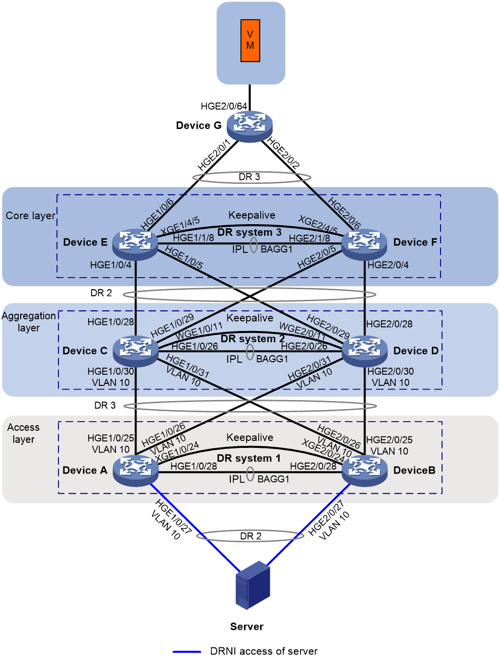
As shown in Figure 1, the user network uses a three-layer architecture: core-aggregation-access. To improve network availability, deploy two devices separately on the core layer, aggregation layer, and access layer. Two devices on each layer form a DR system.
· Device A and Device B form DR system 1, which acts as an access device and connects to Server.
· Device C and Device D form DR system 2, which acts as an aggregation device.
· Device E and Device F form DR system 3, which acts as the core device and connects to VM.
To meet the network access requirements of VM and Server, make sure the DR member devices on the core layer act as both the IPv4 gateway and IPv6 gateway of VM and Server.
To avoid loops between aggregation member ports over an IPL because the DR system splits, the cables are connected incorrectly, or the configuration is incorrect, perform he following tasks:
· Configure STP on the DR member devices.
· Configure the DR member devices on the core layer (Device E and Device F) as the root bridges of STP. If you do not do that, when new devices are added to the STP network, they might dynamically preempt the STP root bridge roles. As a result, the STP network will flap.
|
|
NOTE: This document uses three-layer DRNI+STP+dual-active VLAN gateways as an example to describe how to configure a multi-layer DRNI network. The configuration procedure for a two-layer DRNI+STP+dual-active VLAN gateways is similar. |
|
Device |
Interface |
IP address |
Peer device and interface |
|
Device A |
XGE1/0/24 |
IPv4: 220.1.1.1/24 |
Device B XGE2/0/24 |
|
Device B |
XGE2/0/24 |
IPv4: 220.1.1.2/24 |
Device A: XGE1/0/24 |
|
Device C |
WGE1/0/11 |
IPv4: 220.1.1.3/24 |
Device D: WGE2/0/11 |
|
Device D |
WGE2/0/11 |
IPv4: 220.1.1.4/24 |
Device C: WGE1/0/11 |
|
Device E |
XGE1/4/5 |
IPv4: 220.1.1.5/24 |
Device F: XGE2/4/5 |
|
Vlan-int20 |
IPv4: 20.1.1.2/24 IPv6: 20:1::2/64 |
N/A |
|
|
Vlan-int30 |
IPv4: 30.1.1.1/24 IPv6: 30:1::1/64 |
N/A |
|
|
Device F |
XGE2/4/5 |
IPv4: 220.1.1.6/24 |
Device E: XGE1/4/5 |
|
Vlan-int20 |
IPv4: 20.1.1.2/24 IPv6: 20:1::2/64 |
N/A |
|
|
Vlan-int30 |
IPv4: 30.1.1.1/24 IPv6: 30:1::1/64 |
N/A |
Applicable product matrix
|
|
IMPORTANT: In addition to running an applicable software version, you must also install the most recent patch, if any. |
|
Device |
Software version |
|
S6805, S6825, S6850, S9850, S9820-64H, S9820-8C |
R6635 |
|
S6800, S6860 |
F2715 and higher 27xx versions |
|
S12500X-AF, S6890 |
R2820 |
|
S12500G-AF |
Under verification. To obtain the latest images, contact Technical Support. |
|
S6812, S6813 |
Under development. To obtain the latest images, contact Technical Support. |
Analysis
On Device E and Device F, configure an IPv4 address and an IPv6 address for VLAN-interface 20, which will act as the IPv4 gateway address and IPv6 gateway address of Server, respectively. Configure an IPv4 address and an IPv6 address for VLAN-interface 30, which will act as the IPv4 gateway address and IPv6 gateway address of VM, respectively, so that both IPv4 users and IPv6 users can access the external network through these gateways.
On Device E and Device F, configure the DR member devices as the STP root bridges to eliminate the loops between the DR systems.
Configuring the DR systems
Procedure summary
· Configuring the dual-active gateways
Configuring DRNI
Configuring Device A and Device B
|
Device A |
Device B |
Description |
Remarks |
|
stp global enable |
stp global enable |
Enable the spanning tree protocol globally. |
By default, this feature is enabled on fixed-port switches. |
|
drni role priority 10 |
drni role priority 20 |
Set the DR role priority of a DR member device. |
DRNI assigns the primary or secondary role to a DR member device based on its DR role priority. The smaller the priority value, the higher the priority. The device with the higher priority is the primary device. |
|
drni system-mac 2-2-2 |
drni system-mac 2-2-2 |
Configure the DR system MAC address. |
You must configure the same DR system MAC address for devices in the same DR system. |
|
drni system-number 1 |
drni system-number 2 |
Set the DR system number. |
You must set different DR system numbers for devices in the same DR system. |
|
drni system-priority 123 |
drni system-priority 123 |
Set the DR system priority. |
You must set the same DR system priority for devices in the same DR system. |
|
drni standalone enable |
drni standalone enable |
Enable DRNI standalone mode. |
N/A |
|
drni keepalive ip destination 220.1.1.2 source 220.1.1.1 |
drni keepalive ip destination 220.1.1.1 source 220.1.1.2 |
Configure the destination and source IP addresses of keepalive packets. |
N/A |
|
interface Ten-GigabitEthernet 1/0/24 |
interface Ten-GigabitEthernet 2/0/24 |
Enter the interface view for the keepalive link. |
N/A |
|
port link-mode route |
port link-mode route |
Configure the interface for the keepalive link to operate in route mode as a Layer 3 interface. |
N/A |
|
ip address 220.1.1.1 24 |
ip address 220.1.1.2 24 |
Assign an IP address to a keepalive link interface. |
N/A |
|
quit |
quit |
Return to system view. |
N/A |
|
drni mad exclude interface Ten-GigabitEthernet 1/0/24 |
drni mad exclude interface Ten-GigabitEthernet 2/0/24 |
Exclude the interface used for DR keepalive detection from the shutdown action by DRNI MAD. |
N/A |
|
vlan 20 |
vlan 20 |
Create VLAN 20. |
N/A |
|
quit |
quit |
Return to system view. |
N/A |
|
interface bridge-aggregation 1 |
interface bridge-aggregation 1 |
Create the Layer 2 aggregate interface to be used as the IPP and enter Layer 2 aggregate interface view. |
N/A |
|
quit |
quit |
Return to system view. |
N/A |
|
interface HundredGigE 1/0/28 |
interface HundredGigE 2/0/28 |
Enter the view of physical interfaces on the IPL. |
N/A |
|
port link-aggregation group 1 |
port link-aggregation group 1 |
Assign the physical interfaces on the IPL to the aggregation group for the IPL (aggregation group 1). |
N/A |
|
quit |
quit |
Return to system view. |
N/A |
|
interface bridge-aggregation 1 |
interface bridge-aggregation 1 |
Enter the view of the aggregation group for the IPL. |
N/A |
|
undo mac-address static source-check enable |
undo mac-address static source-check enable |
Disable source MAC check on an interface. |
N/A |
|
link-aggregation mode dynamic |
link-aggregation mode dynamic |
Configure the aggregate interface to operate in dynamic mode. |
N/A |
|
port drni intra-portal-port 1 |
port drni intra-portal-port 1 |
Specify the aggregate interface (Bridge-Aggregation 1) as the IPP. |
N/A |
|
quit |
quit |
Return to system view. |
N/A |
|
interface bridge-aggregation 2 |
interface bridge-aggregation 2 |
Create an aggregate interface connecting to Server. |
N/A |
|
link-aggregation mode dynamic |
link-aggregation mode dynamic |
Configure the aggregate interface connecting to Server to operate in dynamic mode. |
N/A |
|
port drni group 2 |
port drni group 2 |
Assign the Layer 2 aggregate interface (Bridge-Aggregation 2) to DR group 2. |
N/A |
|
quit |
quit |
Return to system view. |
N/A |
|
interface bridge-aggregation 3 |
interface bridge-aggregation 3 |
Create an aggregate interface connecting to Device C and Device D. |
N/A |
|
link-aggregation mode dynamic |
link-aggregation mode dynamic |
Configure the aggregate interface connecting to Device C and Device D to operate in dynamic mode. |
N/A |
|
port drni group 3 |
port drni group 3 |
Assign the Layer 3 aggregate interface (Bridge-Aggregation 3) to DR group 2. |
N/A |
|
quit |
quit |
Return to system view. |
N/A |
|
interface HundredGigE 1/0/27 |
interface HundredGigE 2/0/27 |
Enter the view of the physical interfaces connecting the DR system to Server. |
N/A |
|
port link-aggregation group 2 |
port link-aggregation group 2 |
Assign the interfaces to a DR group. |
N/A |
|
quit |
quit |
Return to system view. |
N/A |
|
interface bridge-aggregation 2 |
interface bridge-aggregation 2 |
Enter the view of an aggregate interface. |
N/A |
|
port link-type trunk |
port link-type trunk |
Set the link type of the aggregate interface to trunk. |
N/A |
|
undo port trunk permit vlan 1 |
undo port trunk permit vlan 1 |
Remove the trunk port from VLAN 1. |
N/A |
|
port trunk permit vlan 20 |
port trunk permit vlan 20 |
Assign the interface to the specified VLAN. |
N/A |
|
stp edged-port |
stp edged-port |
Specify the aggregate interface as an STP edge port. |
N/A |
|
quit |
quit |
Return to system view. |
N/A |
|
interface range HundredGigE 1/0/25 HundredGigE 1/0/26 |
interface range HundredGigE 2/0/25 HundredGigE 2/0/26 |
Enter the view of the physical interfaces connecting the DR system to Device C and Device D. |
N/A |
|
port link-aggregation group 3 |
port link-aggregation group 3 |
Assign the interfaces to a DR group. |
N/A |
|
quit |
quit |
Return to system view. |
N/A |
|
interface bridge-aggregation 3 |
interface bridge-aggregation 3 |
Enter the view of an aggregate interface. |
N/A |
|
port link-type trunk |
port link-type trunk |
Set the link type of the aggregate interface to trunk. |
N/A |
|
undo port trunk permit vlan 1 |
undo port trunk permit vlan 1 |
Remove the trunk port from VLAN 1. |
N/A |
|
port trunk permit vlan 20 |
port trunk permit vlan 20 |
Assign the interface to the specified VLAN. |
N/A |
|
quit |
quit |
Return to system view. |
N/A |
|
link-aggregation global load-sharing algorithm 7 |
link-aggregation global load-sharing algorithm 7 |
Configure a link aggregation load sharing algorithm. |
To identify whether traffic is load-shared among aggregation member ports, use the display counters command to view the traffic on each aggregation group member port. If traffic is not well load-shared, you can use this command to specify a proper link aggregation load sharing algorithm. This command is not supported on the S6812 and S6813 switches. |
Configuring Device C and Device D
|
Device C |
Device D |
Description |
Remarks |
|
stp global enable |
stp global enable |
Enable the spanning tree protocol globally. |
By default, this feature is enabled on fixed-port switches. |
|
drni system-mac 1-1-1 |
drni system-mac 1-1-1 |
Configure the DR system MAC address. |
You must configure the same DR system MAC address for devices in the same DR system. |
|
drni system-number 1 |
drni system-number 2 |
Set the DR system number. |
You must set different DR system numbers for devices in the same DR system. |
|
drni system-priority 124 |
drni system-priority 124 |
Set the DR system priority. |
You must set the same DR system priority for devices in the same DR system. |
|
drni role priority 10 |
drni role priority 20 |
Set the DR role priority of a DR member device. |
DRNI assigns the primary or secondary role to a DR member device based on its DR role priority. The smaller the priority value, the higher the priority. The device with the higher priority is the primary device. |
|
drni standalone enable |
drni standalone enable |
Enable DRNI standalone mode. |
N/A |
|
drni keepalive ip destination 220.1.1.4 source 220.1.1.3 |
drni keepalive ip destination 220.1.1.3 source 220.1.1.4 |
Configure the destination and source IP addresses of keepalive packets. |
N/A |
|
interface Twenty-FiveGigE 1/0/11 |
interface Twenty-FiveGigE 2/0/11 |
Enter the interface view for the keepalive link. |
N/A |
|
port link-mode route |
port link-mode route |
Configure the interface for the keepalive link to operate in route mode as a Layer 3 interface. |
N/A |
|
ip address 220.1.1.3 24 |
ip address 220.1.1.4 24 |
Assign an IP address to the interface for the keepalive link. |
N/A |
|
quit |
quit |
Return to system view. |
N/A |
|
drni mad exclude interface Twenty-FiveGigE 1/0/11 |
drni mad exclude interface Twenty-FiveGigE 2/0/11 |
Exclude the interface used for DR keepalive detection from the shutdown action by DRNI MAD. |
N/A |
|
vlan 20 |
vlan 20 |
Create VLAN 20. |
N/A |
|
quit |
quit |
Return to system view. |
N/A |
|
interface bridge-aggregation 1 |
interface bridge-aggregation 1 |
Create the Layer 2 aggregate interface to be used as the IPP and enter Layer 2 aggregate interface view. |
N/A |
|
quit |
quit |
Return to system view. |
N/A |
|
interface HundredGigE 1/0/26 |
interface HundredGigE 2/0/26 |
Enter the view of physical interfaces on the IPL. |
N/A |
|
port link-aggregation group 1 |
port link-aggregation group 1 |
Assign the physical interfaces on the IPL to the aggregation group for the IPL (aggregation group 1). |
N/A |
|
interface bridge-aggregation 1 |
interface bridge-aggregation 1 |
Enter the view of the aggregation group for the IPL. |
N/A |
|
undo mac-address static source-check enable |
undo mac-address static source-check enable |
Disable source MAC check on an interface. |
N/A |
|
link-aggregation mode dynamic |
link-aggregation mode dynamic |
Configure the aggregate interface to operate in dynamic mode. |
N/A |
|
port drni intra-portal-port 1 |
port drni intra-portal-port 1 |
Specify the aggregate interface (Bridge-Aggregation 1) as the IPP. |
N/A |
|
quit |
quit |
Return to system view. |
N/A |
|
interface bridge-aggregation 2 |
interface bridge-aggregation 2 |
Create an aggregate interface connecting to Device E and Device F. |
N/A |
|
link-aggregation mode dynamic |
link-aggregation mode dynamic |
Configure the aggregate interface connecting to Device E and Device F to operate in dynamic mode. |
N/A |
|
port lacp system-priority 101 |
port lacp system-priority 100 |
Set the LACP priority. |
Set different LACP priorities for different DR member devices, so that only member ports with a higher priority are selected upon brain split. |
|
port drni group 2 |
port drni group 2 |
Assign the Layer 2 aggregate interface (Bridge-Aggregation 2) to DR group 2. |
N/A |
|
quit |
quit |
Return to system view. |
N/A |
|
interface bridge-aggregation 3 |
interface bridge-aggregation 3 |
Create an aggregate interface connecting to Device A and Device B. |
N/A |
|
link-aggregation mode dynamic |
link-aggregation mode dynamic |
Configure the aggregate interface connecting to Device A and Device B to operate in dynamic mode. |
N/A |
|
port lacp system-priority 101 |
port lacp system-priority 100 |
Set the LACP priority. |
Set different LACP priorities for different DR member devices, so that only member ports with a higher priority are selected upon brain split. |
|
port drni group 3 |
port drni group 3 |
Assign the Layer 3 aggregate interface (Bridge-Aggregation 3) to DR group 3. |
N/A |
|
quit |
quit |
Return to system view. |
N/A |
|
interface range HundredGigE 1/0/28 HundredGigE 1/0/29 |
interface range HundredGigE 2/0/28 HundredGigE 2/0/29 |
Enter the view of the physical interfaces connecting the DR system to Device E and Device F. |
N/A |
|
port link-aggregation group 2 |
port link-aggregation group 2 |
Assign the interfaces to a DR group. |
N/A |
|
quit |
quit |
Return to system view. |
N/A |
|
interface bridge-aggregation 2 |
interface bridge-aggregation 2 |
Enter the view of an aggregate interface. |
N/A |
|
port link-type trunk |
port link-type trunk |
Set the link type of the aggregate interface to trunk. |
N/A |
|
undo port trunk permit vlan 1 |
undo port trunk permit vlan 1 |
Remove the trunk port from VLAN 1. |
N/A |
|
port trunk permit vlan 20 |
port trunk permit vlan 20 |
Assign the interface to the specified VLAN. |
N/A |
|
interface range HundredGigE 1/0/30 HundredGigE 1/0/31 |
interface range HundredGigE 2/0/30 HundredGigE 2/0/31 |
Enter the view of the physical interfaces connecting the DR system to Device A and Device B. |
N/A |
|
port link-aggregation group 3 |
port link-aggregation group 3 |
Assign the interfaces to a DR group. |
N/A |
|
quit |
quit |
Return to system view. |
N/A |
|
interface bridge-aggregation 3 |
interface bridge-aggregation 3 |
Enter the view of an aggregate interface. |
N/A |
|
port link-type trunk |
port link-type trunk |
Set the link type of the aggregate interface to trunk. |
N/A |
|
undo port trunk permit vlan 1 |
undo port trunk permit vlan 1 |
Remove the trunk port from VLAN 1. |
N/A |
|
port trunk permit vlan 20 |
port trunk permit vlan 20 |
Assign the interface to the specified VLAN. |
N/A |
|
quit |
quit |
Return to system view. |
N/A |
|
link-aggregation global load-sharing algorithm 7 |
link-aggregation global load-sharing algorithm 7 |
Configure a link aggregation load sharing algorithm. |
To identify whether traffic is load-shared among aggregation member ports, use the display counters command to view the traffic on each aggregation group member port. If traffic is not well load-shared, you can use this command to specify a proper link aggregation load sharing algorithm. This command is not supported on the S6812 and S6813 switches. |
Configuring Device E and Device F
|
Device E |
Device F |
Description |
Remarks |
|
stp global enable |
stp global enable |
Enable the spanning tree protocol globally. |
By default, this feature is enabled on fixed-port switches. |
|
drni system-mac 1-2-3 |
drni system-mac 1-2-3 |
Configure the DR system MAC address. |
You must configure the same DR system MAC address for devices in the same DR system. |
|
drni system-number 1 |
drni system-number 2 |
Set the DR system number. |
You must set different DR system numbers for devices in the same DR system. |
|
drni system-priority 122 |
drni system-priority 122 |
Set the DR system priority. |
You must set the same DR system priority for devices in the same DR system. |
|
drni role priority 10 |
drni role priority 20 |
Set the DR role priority of a DR member device. |
DRNI assigns the primary or secondary role to a DR member device based on its DR role priority. The smaller the priority value, the higher the priority. The device with the higher priority is the primary device. |
|
drni standalone enable |
drni standalone enable |
Enable DRNI standalone mode. |
N/A |
|
drni keepalive ip destination 220.1.1.6 source 220.1.1.5 |
drni keepalive ip destination 220.1.1.5 source 220.1.1.6 |
Configure the destination and source IP addresses of keepalive packets. |
N/A |
|
interface Ten-GigabitEthernet 1/4/5 |
interface Ten-GigabitEthernet 2/4/5 |
Enter the interface view for the keepalive link. |
N/A |
|
port link-mode route |
port link-mode route |
Configure the interface for the keepalive link to operate in route mode as a Layer 3 interface. |
N/A |
|
ip address 220.1.1.5 24 |
ip address 220.1.1.6 24 |
Assign an IP address to the interface for the keepalive link. |
N/A |
|
quit |
quit |
Return to system view. |
N/A |
|
drni mad exclude interface Ten-GigabitEthernet 1/4/5 |
drni mad exclude interface Ten-GigabitEthernet 2/4/5 |
Exclude the interface used for DR keepalive detection from the shutdown action by DRNI MAD. |
N/A |
|
interface bridge-aggregation 1 |
interface bridge-aggregation 1 |
Create the Layer 2 aggregate interface to be used as the IPP and enter Layer 2 aggregate interface view. |
N/A |
|
quit |
quit |
Return to system view. |
N/A |
|
Interface HundredGigE 1/1/8 |
interface HundredGigE 2/1/8 |
Enter the view of physical interfaces on the IPL. |
N/A |
|
port link-aggregation group 1 |
port link-aggregation group 1 |
Assign the physical interfaces on the IPL to the aggregation group for the IPL (aggregation group 1). |
N/A |
|
quit |
quit |
Return to system view. |
N/A |
|
interface bridge-aggregation 1 |
interface bridge-aggregation 1 |
Enter the view of the aggregation group for the IPL. |
N/A |
|
undo mac-address static source-check enable |
undo mac-address static source-check enable |
Disable source MAC check on an interface. |
N/A |
|
link-aggregation mode dynamic |
link-aggregation mode dynamic |
Configure the aggregate interface to operate in dynamic mode. |
N/A |
|
port drni intra-portal-port 1 |
port drni intra-portal-port 1 |
Specify the aggregate interface (Bridge-Aggregation 1) as the IPP. |
N/A |
|
quit |
quit |
Return to system view. |
N/A |
|
interface bridge-aggregation 2 |
interface bridge-aggregation 2 |
Create an aggregate interface connecting to Device C and Device D. |
N/A |
|
link-aggregation mode dynamic |
link-aggregation mode dynamic |
Configure the aggregate interface connecting to Device C and Device D to operate in dynamic mode. |
N/A |
|
port drni group 2 |
port drni group 2 |
Assign the Layer 2 aggregate interface (Bridge-Aggregation 2) to DR group 2. |
N/A |
|
quit |
quit |
Return to system view. |
N/A |
|
interface bridge-aggregation 3 |
interface bridge-aggregation 3 |
Create an aggregate interface connecting to Device G. |
N/A |
|
link-aggregation mode dynamic |
link-aggregation mode dynamic |
Configure the aggregate interface connecting to Device G to operate in dynamic mode. |
N/A |
|
port drni group 3 |
port drni group 3 |
Assign the Layer 3 aggregate interface (Bridge-Aggregation 3) to DR group 3. |
N/A |
|
quit |
quit |
Return to system view. |
N/A |
|
interface range HundredGigE 1/0/4 HundredGigE 1/0/5 |
interface range HundredGigE 2/0/4 HundredGigE 2/0/5 |
Enter the view of the physical interfaces connecting the DR system to Device C and Device D. |
N/A |
|
port link-aggregation group 2 |
port link-aggregation group 2 |
Assign the interfaces to a DR group. |
N/A |
|
quit |
quit |
Return to system view. |
N/A |
|
interface HundredGigE1/0/6 |
interface HundredGigE2/0/6 |
Enter the view of the physical interfaces connecting the DR system to VM. |
N/A |
|
port link-aggregation group 3 |
port link-aggregation group 3 |
Assign the interfaces to a DR group. |
N/A |
|
quit |
quit |
Return to system view. |
N/A |
|
link-aggregation global load-sharing algorithm 7 |
link-aggregation global load-sharing algorithm 7 |
Configure a link aggregation load sharing algorithm. |
To identify whether traffic is load-shared among aggregation member ports, use the display counters command to view the traffic on each aggregation group member port. If traffic is not well load-shared, you can use this command to specify a proper link aggregation load sharing algorithm. This command is not supported on the S6812 and S6813 switches. |
|
stp instance 0 root primary |
stp instance 0 root primary |
Configure the device as the root bridge. |
N/A |
Configuring the dual-active gateways
|
Device E |
Device F |
Description |
Remarks |
|
vlan 20 30 |
vlan 20 30 |
Create VLANs 20 and 30. |
N/A |
|
interface bridge-aggregation 2 |
interface bridge-aggregation 2 |
Enter the view of the aggregate interface connecting to Device D. |
N/A |
|
port link-type trunk |
port link-type trunk |
Set the link type of the Layer 2 aggregate interface (Bridge-Aggregation 2) to trunk. |
N/A |
|
port trunk permit vlan 20 |
port trunk permit vlan 20 |
Assign the interface to VLAN 20. |
N/A |
|
undo port trunk permit vlan 1 |
undo port trunk permit vlan 1 |
Remove the interface from VLAN 1. |
N/A |
|
port lacp system-priority 101 |
port lacp system-priority 100 |
Set the LACP priority. |
Set different LACP priorities for different DR member devices, so that only member ports with a higher priority are selected upon brain split. |
|
quit |
quit |
Return to system view. |
N/A |
|
interface bridge-aggregation 3 |
interface bridge-aggregation 3 |
Enter the view of the aggregate interface connecting to Device G. |
N/A |
|
port link-type trunk |
port link-type trunk |
Set the link type of the Layer 2 aggregate interface to trunk. |
N/A |
|
port trunk permit vlan 30 |
port trunk permit vlan 30 |
Assign the interface to VLAN 30. |
N/A |
|
undo port trunk permit vlan 1 |
undo port trunk permit vlan 1 |
Remove the interface from VLAN 1. |
N/A |
|
port lacp system-priority 101 |
port lacp system-priority 100 |
Set the LACP priority. |
Set different LACP priorities for different DR member devices, so that only member ports with a higher priority are selected upon brain split. |
|
quit |
quit |
Return to system view. |
N/A |
|
interface vlan-interface 30 |
interface vlan-interface 30 |
Create VLAN-interface 30. |
N/A |
|
ip address 30.1.1.1 255.255.255.0 |
ip address 30.1.1.1 255.255.255.0 |
Assign an IPv4 address to VLAN-interface 30, which is to act as an IPv4 gateway address. |
N/A |
|
mac-address 0030-0030-0030 |
mac-address 0030-0030-0030 |
Assign a MAC address to VLAN-interface 30. |
N/A |
|
ipv6 address 30:1::1 64 |
ipv6 address 30:1::1 64 |
Assign an IPv6 address to VLAN-interface 30, which is to act as an IPv6 gateway address. |
N/A |
|
quit |
quit |
Return to system view. |
N/A |
|
drni mad exclude interface Vlan-interface 30 |
drni mad exclude interface Vlan-interface 30 |
Exclude VLAN-interface 30 from the shutdown action by DRNI MAD. |
N/A |
|
interface vlan-interface 20 |
interface vlan-interface 20 |
Create VLAN-interface 20. |
N/A |
|
ip address 20.1.1.1 255.255.255.0 |
ip address 20.1.1.1 255.255.255.0 |
Assign an IPv4 address to VLAN-interface 20, which is to act as an IPv4 gateway address. |
N/A |
|
mac-address 0020-0020-0021 |
mac-address 0020-0020-0021 |
Assign a MAC address to VLAN-interface 20. |
N/A |
|
ipv6 address 20:1::1 64 |
ipv6 address 20:1::1 64 |
Assign an IPv6 address to VLAN-interface 20, which is to act as an IPv6 gateway address. |
N/A |
|
quit |
quit |
Return to system view. |
N/A |
|
drni mad exclude interface Vlan-interface 20 |
drni mad exclude interface Vlan-interface 20 |
Exclude VLAN-interface 20 from the shutdown action by DRNI MAD. |
N/A |
Configuring the uplink device
|
Device G |
Description |
|
vlan 30 |
Create VLAN 30. |
|
quit |
Return to system view. |
|
interface bridge-aggregation 3 |
Create an aggregate interface. |
|
link-aggregation mode dynamic |
Configure the aggregate interface to operate in dynamic mode. |
|
Interface range HundredGigE 2/0/1 HundredGigE 2/0/2 |
Enter the view of the physical interfaces connecting to Device E and Device F. |
|
port link-aggregation group 3 |
Assign physical interfaces to an aggregation group. |
|
quit |
Return to system view. |
|
interface bridge-aggregation 3 |
Enter the view of an aggregate interface. |
|
port link-type trunk |
Set the link type of the aggregate interface to trunk. |
|
port trunk permit vlan 30 |
Assign the aggregate interface to VLAN 30. |
|
undo port trunk permit vlan 1 |
Remove the trunk port from VLAN 1. |
|
Interface HundredGigE 2/0/64 |
Enter the view of the physical interface connecting to VM. |
|
port access vlan 30 |
Set the link type of the interface to access, and assign it to VLAN 30 |
Traffic forwarding models
Underlay traffic characteristics
The forwarding model matrix provides the following characteristics of underlay traffic:
· No.—Traffic number in the U-X-XXX format:
¡ U—Underlay traffic.
¡ X—Protocol number, which can be 4 (IPv4) or 6 (IPv6).
¡ XXX—Traffic sequence number.
· Traffic type—Type of underlay traffic, which can be IPv4 known unicast or IPv6 known unicast.
· Direction—Direction of underlay traffic. The value is south-north, which indicates traffic from the south to north.
· Forwarding path—Nodes that underlay traffic traverses.
· Traffic simulation—Traffic simulation method. Typically, a tester is used to simulate server traffic.
· Load—Traffic size, which can be light (less than 1000 flows) and heavy (more than 1000 flows).
Underlay traffic forwarding models
|
No. |
Traffic type |
Direction |
Forwarding path |
Traffic simulation |
Load |
Description |
|
U-4-101 |
IPv4 known unicast |
South to north |
Server > DR system 1 > DR system 2 > DR system 3 > VM |
Tester |
Light |
N/A |
|
U-6-101 |
IPv6 known unicast |
South to north |
Server > DR system 1 > DR system 2 > DR system 3 > VM |
Tester |
Light |
N/A |
Testing network convergence upon single points of failure
Table 1 Network convergence upon single points of failure
|
Device |
Failure type |
Traffic interruption time |
|
DR |
Single point of failure on DR member links |
≤ 100 ms |
|
Single point of failure restored on DR member links |
≤ 100 ms |
|
|
IPL failure |
≤ 500 ms |
|
|
IPL failure restored |
0 ms |
|
|
Keepalive link failure |
0 ms |
|
|
Keepalive link failure restored |
0 ms |
|
|
Keepalive link and IPL failure |
≤ 3000 ms |
|
|
Keepalive link and IPL restored |
≤ 4000 ms |
|
|
Upgrading the devices |
≤ 500ms (legacy method, in which two DR member devices are separately upgraded) |
|
|
Expanding the network |
0 ms |
|
|
Replacing hardware |
Fixed-port device: ≤ 500 ms Modular device: · Device replacement: ≤ 1000 ms. · Switching fabric module replacement: 0 ms. · Service module replacement: ≤ 500 ms. |
Verifying the configuration
Verifying the status of the DR system
Verify that the DR system is working correctly on Device E and Device F. Use Device E as an example. Configure Device F in the same way Device E is configured.
# Display summary information about the IPP and DR interface.
[DeviceE] display drni summary
Flags: A -- Aggregate interface down, B -- No peer DR interface configured
C -- Configuration consistency check failed
IPP: BAGG1
IPP state (cause): UP
Keepalive link state (cause): UP
DR interface information
DR interface DR group Local state (cause) Peer state Remaining down time(s)
BAGG2 2 UP UP -
BAGG3 3 UP UP -
# Verify that keepalive link is working correctly.
[DeviceE] display drni keepalive
Neighbor keepalive link status (cause): Up
Neighbor is alive for: 774 s 381 ms
Keepalive packet transmission status:
Sent: Successful
Received: Successful
Last received keepalive packet information:
Source IP address: 220.1.1.2
Time: 2022/02/07 06:50:17
Action: Accept
Distributed relay keepalive parameters:
Destination IP address: 220.1.1.6
Source IP address: 220.1.1.5
Keepalive UDP port : 6400
Keepalive VPN name : N/A
Keepalive interval : 1000 ms
Keepalive timeout : 5 sec
Keepalive hold time: 3 sec
# Display the DR system information.
[DeviceE] display drni system
System information
Local system number: 1 Peer system number: 2
Local system MAC: 0001-0002-0003 Peer system MAC: 0001-0002-0003
Local system priority: 122 Peer system priority: 122
Local bridge MAC: 5cc9-995f-7d7e Peer bridge MAC: 5cc9-995f-79fa
Local effective role: Secondary Peer effective role: Primary
Health level: 0
Standalone mode on split: Enabled
In standalone mode: No
System timer information
Timer State Value (s) Remaining time (s)
Auto recovery Disabled - -
Restore delay Disabled 180 -
Consistency-check delay Disabled 90 -
Standalone delay Disabled 0 -
Role to None delay Disabled 60 -
# Display detailed information about the IPP and DR interfaces.
[DeviceE] display drni verbose
Flags: A -- Home_Gateway, B -- Neighbor_Gateway, C -- Other_Gateway,
D -- IPP_Activity, E -- DRCP_Timeout, F -- Gateway_Sync,
G -- Port_Sync, H -- Expired
IPP/IPP ID: BAGG1/1
State: UP
Cause: -
Local DRCP flags/Peer DRCP flags: ABDFG/ABDFG
Local Selected ports (index): HGE1/1/8 (40)
Peer Selected ports indexes: 235
DR interface/DR group ID: BAGG2/2
Local DR interface state: UP
Peer DR interface state: UP
DR group state: UP
Local DR interface down cause: -
Remaining DRNI DOWN time: -
Local DR interface LACP MAC: Config=N/A, Effective=0001-0002-0003
Peer DR interface LACP MAC: Config=N/A, Effective=0001-0002-0003
Local DR interface LACP priority: Config=32768, Effective=122
Peer DR interface LACP priority: Config=32768, Effective=122
Local DRCP flags/Peer DRCP flags: ABDFG/ABDFG
Local Selected ports (index): HGE1/1/4 (20), HGE1/1/5 (25)
Peer Selected ports indexes: 215, 220
DR interface/DR group ID: BAGG3/3
Local DR interface state: UP
Peer DR interface state: UP
DR group state: UP
Local DR interface down cause: -
Remaining DRNI DOWN time: -
Local DR interface LACP MAC: Config=N/A, Effective=0001-0002-0003
Peer DR interface LACP MAC: Config=N/A, Effective=0001-0002-0003
Local DR interface LACP priority: Config=32768, Effective=122
Peer DR interface LACP priority: Config=32768, Effective=122
Local DRCP flags/Peer DRCP flags: ABDFG/ABDFG
Local Selected ports (index): FGE1/2/1 (45)
Peer Selected ports indexes: 240
Verifying that the STP state is normal
# Display the STP state after the DR systems are cascaded. On Device A, Device B, Device C, Device D, Device E, and Device F, the STP state of each aggregate interface is FORWARDING, and the root bridge is 0.0001-0002-0003.
[DeviceE] display stp brief
MST ID Port Role STP State Protection
0 Bridge-Aggregation2 (DR) DESI FORWARDING NONE
0 Bridge-Aggregation3 (DR) DESI FORWARDING NONE
[DeviceE] display stp root
MST ID Root Bridge ID ExtPathCost IntPathCost Root Port
0 0.0001-0002-0003 0 0
[DeviceF] display stp brief
MST ID Port Role STP State Protection
0 Bridge-Aggregation2 (DR) DESI FORWARDING NONE
0 Bridge-Aggregation3 (DR) DESI FORWARDING NONE
[DeviceF] display stp root
MST ID Root Bridge ID ExtPathCost IntPathCost Root Port
0 0.0001-0002-0003 0 0
[DeviceC] display stp brief
MST ID Port Role STP State Protection
0 Bridge-Aggregation2 (DR) ROOT FORWARDING NONE
0 Bridge-Aggregation3 (DR) DESI FORWARDING NONE
[DeviceC] display stp root
MST ID Root Bridge ID ExtPathCost IntPathCost Root Port
0 0.0001-0002-0003 1 0 BAGG2
[DeviceD] display stp brief
MST ID Port Role STP State Protection
0 Bridge-Aggregation2 (DR) ROOT FORWARDING NONE
0 Bridge-Aggregation3 (DR) DESI FORWARDING NONE
[DeviceD] display stp root
MST ID Root Bridge ID ExtPathCost IntPathCost Root Port
0 0.0001-0002-0003 1 0 BAGG2
[DeviceA] display stp brief
MST ID Port Role STP State Protection
0 Bridge-Aggregation2 (DR) ROOT FORWARDING NONE
0 Bridge-Aggregation3 (DR) DESI FORWARDING NONE
[DeviceA] display stp root
MST ID Root Bridge ID ExtPathCost IntPathCost Root Port
0 0.0001-0002-0003 1 0 BAGG2
[DeviceB] display stp brief
MST ID Port Role STP State Protection
0 Bridge-Aggregation2 (DR) ROOT FORWARDING NONE
0 Bridge-Aggregation3 (DR) DESI FORWARDING NONE
[DeviceB] display stp root
MST ID Root Bridge ID ExtPathCost IntPathCost Root Port
0 0.0001-0002-0003 1 0 BAGG2
Upgrading the devices
This section describes how to upgrade the software for DR member devices.
Checking the environment
Execute the commands in "Verifying the configuration" and the following commands to verify that the devices are available for an upgrade.
|
DR 1 |
DR 2 |
Description |
|
display device |
display device |
Displays device information. |
|
display boot-loader |
display boot-loader |
Displays current software images and startup software images. |
|
display version |
display version |
Displays system version information. |
Upgrading the devices
See H3C Switches DR System Upgrade & Replacement & Expansion Guide.
Verifying the traffic interruption time during the upgrade
Verify that the legacy upgrade method is used, in which the two DR member devices are upgraded one by one. Verify that the traffic downtime of a member device is less than 500 ms upon failover and 150 ms upon fallback. For more information, see “Testing network convergence upon single points of failure.”
Verifying the upgrade result
Execute the commands in "Verifying the configuration" and the following commands to verify that the device is upgraded successfully.
|
DR 1 |
DR 2 |
Description |
|
display device |
display device |
Displays device information. |
|
display boot-loader |
display boot-loader |
Displays current software images and startup software images. |
|
display version |
display version |
Displays system version information. |
Expanding the network
An expansion operation adds two leaf devices.
Checking the environment
Execute the commands in "Verifying the configuration" and the following commands to verify that the device is available for an expansion.
|
DR 1 |
DR 2 |
Description |
|
display device |
display device |
Displays summary information about the IPP and DR interfaces. |
|
display boot-loader |
display boot-loader |
Displays current software images and startup software images. |
|
display version |
display version |
Displays system version information. |
Expanding the network
1. Disconnect the device from network management systems.
2. Upgrade the software of the device as needed.
3. Preconfigure the device.
4. Connect the device to network management systems.
5. Incorporate the device on the controller.
Verifying the traffic interruption time
For more information, see “Testing network convergence upon single points of failure.”
Verifying the expansion result
Execute the following commands to verify that the device is added successfully.
|
DR 1 |
DR 2 |
Description |
|
display device |
display device |
Displays device information. |
|
display boot-loader |
display boot-loader |
Displays current software images and startup software images. |
|
display version |
display version |
Displays system version information. |
Replacing hardware
Replacing a service module
Checking the environment
Execute the commands in "Verifying the configuration" and the following commands to verify that the device is available for a replacement.
|
DR 1 |
DR 2 |
Description |
|
display device |
display device |
Displays device information. |
|
display boot-loader |
display boot-loader |
Displays current software images and startup software images. |
|
display version |
display version |
Displays system version information. |
Replacing hardware
Switch service and management traffic on the target service module to other service modules.
Power off the device and replace the service module, or replace the service module when the device is running. For more information, see the installation guides for the service module.
For details, see H3C Switches DR System Upgrade & Replacement & Expansion Guide.
Verifying the traffic interruption time
For more information, see “Testing network convergence upon single points of failure.”
Verifying the replacement result
Execute the commands in "Checking the environment."
Replacing a switching fabric module
Checking the environment
Execute the commands in "Verifying the configuration" and the following commands to verify that the device is available for a replacement.
|
DR 1 |
DR 2 |
Description |
|
display device |
display device |
Displays device information. |
|
display boot-loader |
display boot-loader |
Displays current software images and startup software images. |
|
display version |
display version |
Displays system version information. |
Replacing hardware
Power off the device and replace the switching fabric module, or replace the switching fabric module when the device is running. For more information, see the installation guides for the switching fabric module.
Verifying the traffic interruption time
For more information, see “Testing network convergence upon single points of failure.”
Verifying the replacement result
Execute the commands in "Checking the environment."
Replace a device
Checking the environment
Execute the commands in "Verifying the configuration" and the following commands to verify that the device is available for a replacement.
|
DR 1 |
DR 2 |
Description |
|
display device |
display device |
Displays device information. |
|
display boot-loader |
display boot-loader |
Displays current software images and startup software images. |
|
display version |
display version |
Displays system version information. |
Replacing hardware
See H3C Switches DR System Upgrade & Replacement & Expansion Guide.
Verifying the traffic interruption time
For more information, see “Testing network convergence upon single points of failure.”
Verifying the replacement result
Execute the commands in "Checking the environment."