- Table of Contents
-
- H3C Data Center Switches DRNI Configuration Guide-6W103
- 00-DRNI network planning
- 01-DRNI+IPv4 and IPv6 Dual-Active VLAN Gateway Configuration Example
- 02-Multi-Layer DRNI+STP+Dual-Active VLAN Gateway Configuration Examples
- 03-Multi-Layer DRNI+Dual-Active VLAN Gateway+OSPF Configuration Examples
- 04-Multi-tier DRNI+Spine Gateways+ECMP Paths to External Network Configuration Example
- 05-DRNI and VRRP Configuration Example
- 06-DRNI+RDMA Configuration Example
- 07-DRNI and EVPN Distributed Gateway (IS-IS for underlay routing) Configuration Example
- 08-DRNI and EVPN Distributed Gateway (BGP for Underlay Routing) Configuration Example
- 09-DRNI+EVPN Distributed Gateway (OSPF on Underlay Network)+DHCP Relay+Microsegmentation+Service Chain Configuration Example
- 10-DRNI+EVPN Centralized Gateway Configuration Example
- 11-Access to DRNI Through Dynamic Routing and Distributed EVPN Gateways Configuration Example
- 12-DRNI+EVPN+Monitor Link Configuration Examples
- 13-DRNI and MVXLAN Configuration Example
- 14-DRNI and DCI Configuration Example
- 15-DRNI+EVPN DC Switchover Upon Border Failure Configuration Examples
- Related Documents
-
| Title | Size | Download |
|---|---|---|
| 00-DRNI network planning | 986.45 KB |
Comparison between IRF and DRNI
Restrictions and guidelines for DR system setup
Routing neighbor relationship setup on dual-active VLAN interfaces using DRNI virtual IP addresses
Restrictions and guidelines for single-homed servers attached to non-DR interfaces
Restrictions and guidelines for routing configuration
Distributed gateway deployment
Centralized gateway deployment
Basic configuration restrictions and guidelines
Restrictions and guidelines for IPL ACs
MAC address configuration restrictions and guidelines
Leaf device configuration restrictions and guidelines
Border and ED configuration restrictions and guidelines
Restrictions and guidelines for server access in active/standby mode
Routing neighbor relationship setup on a DR system formed by distributed EVPN gateways
EVPN DRNI, microsegmentation, and service chain
High availability of leaf devices
DRNI network planning
Comparison between IRF and DRNI
The Intelligent Resilient Framework (IRF) technology is developed by H3C to virtualize multiple physical devices at the same layer into one virtual fabric to provide data center class availability and scalability. IRF virtualization technology offers processing power, interaction, unified management, and uninterrupted maintenance of multiple devices.
Distributed Resilient Network Interconnect (DRNI) virtualizes two physical devices into one system through multi-chassis link aggregation for device redundancy and traffic load sharing.
Table 1 shows the differences between IRF and DRNI. For high availability and short service interruption during software upgrade, use DRNI. You cannot use IRF and DRNI in conjunction on the same device.
Table 1 Comparison between IRF and DRNI
|
Item |
IRF |
DRNI |
|
Control plane |
· The IRF member devices have a unified control plane for central management. · The IRF member devices synchronize all forwarding entries. |
· The control plane of the DR member devices is separate. · The DR member devices synchronize entries such as MAC, ARP, and ND entries. |
|
Device requirements |
· Hardware: The chips of the IRF member devices must have the same architecture, and typically the IRF member devices are from the same series. · Software: The IRF member devices must run the same software version. |
· Hardware: The DR member devices can be different models. · Software: Some device models can run different software versions when they act as DR member devices. Full support for different software versions will be implemented in the future. |
|
Software upgrade |
· The IRF member devices are upgraded simultaneously or separately. A separate upgrade is complex. · Services are interrupted for about 2 seconds during an upgrade. |
The DR member devices are upgrade separately, and the service interruption time is shorter than 1 second during an upgrade. If the software supports graceful insertion and removal (GIR), an upgrade does not interrupt services. For more information about upgrading the DR member devices by using GIR, see the DRNI upgrade guide. |
|
Management |
The IRF member devices are configured and managed in a unified manner. Single points of failure might occur when a controller manages the IRF member devices. |
The DR member devices are configured separately, and they can perform configuration consistency check for you to remove inconsistencies in the configuration that affects operation of the DR system. You must ensure that service features also have consistent configuration. The DR member devices are managed separately. No single point of failure will occur when a controller manages the DR member devices. |
|
|
NOTE: GIR enables you to gracefully isolate a device from the network for device maintenance or upgrade. GIR minimizes service interruption by instructing the affected protocols (for example, routing protocols) to isolate the device and switch over to the redundant path. You do not need to configure graceful switchover protocol by protocol. For more information about GIR, see Fundamentals Configuration Guide for the devices. |
Overlay network planning
H3C offers the following overlay network models for DRNI:
· Three-tiered overlay—The overlay network is formed by the leaf, spine, and border tiers, as shown in Figure 1. Use this model if the border devices do not have enough downlink interfaces to connect to all leaf devices. The spine devices act as route reflectors (RR) in the network.
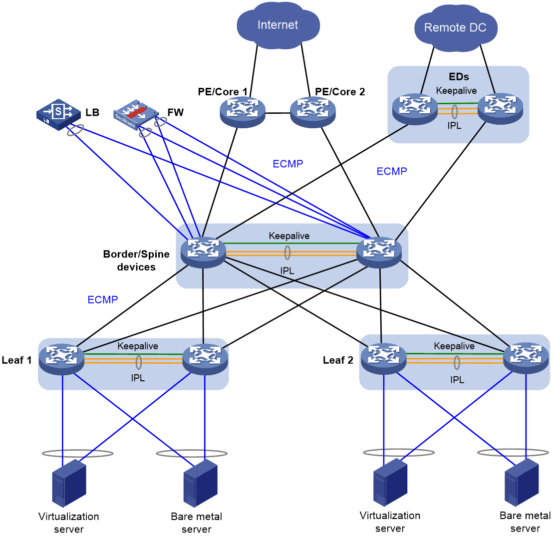
· Two-tiered overlay—The overlay network is formed by the leaf and spine tiers, and the spine devices are also border devices, as shown in Figure 2.
Figure 1 Three-tiered overlay network model
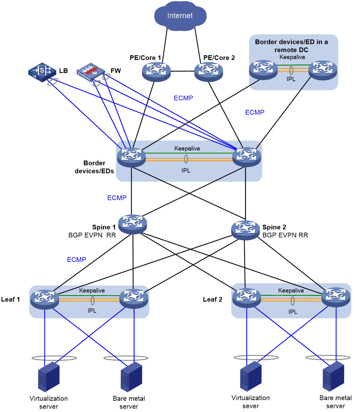
Figure 2 Two-tiered overlay network model
The overlay network contains the following device roles:
· Border device—A border gateway with DRNI configured. The border devices are attached to firewalls and load balancers by using DR interfaces. The border devices use Layer 3 Ethernet interfaces to connect to the spine or leaf devices, and traffic is load shared among the Layer 3 Ethernet links based on ECMP routes.
On a border device, you can use a Layer 3 Ethernet interface, VLAN interface, or DR interface to establish Layer 3 connections with a PE or core device. As a best practice, use Layer 3 Ethernet interfaces.
· Edge device (ED)—A device providing Layer 2 and Layer 3 connectivity to another data center by using VXLAN. You can deploy independent EDs, configure EDs to be collocated with border devices, or configure a device to act as an ED, border, and spine device.
· Spine device—An RR does not have DRNI configuration and reflects BGP routes between the border and leaf tiers in the three-tiered network model. An RR performs only underlay forwarding, and ECMP routes are used for traffic load sharing among the spine, border, and leaf tiers.
In a small network, spine devices can be collocated with border devices.
· Leaf device—A DRNI-configured gateway for the servers. If the server NICs operate in bond4 mode for load sharing, a leaf device is connected to the servers by using DR interfaces. If the server NICs operate in bond1 mode for link backup, a leaf device is connected to the servers by using physical interfaces assigned to the same VLAN as the servers. As a best practice to reduce active/standby NIC switchovers upon link flapping, disable active link preemption or set a preemption delay.
For high availability, make sure the servers are dualhomed to the leaf devices.
A leaf device is connected to upstream devices by using Layer 3 Ethernet interfaces, and ECMP routes are configured for high availability and load sharing.
· Firewall (FW)—An internal firewall attached to the DR interfaces on the border devices by using two aggregate interfaces, one for the uplink and one for the downlink. Static routes are configured to enable Layer 3 communication between the firewall and border devices.
· Load balancer (LB)—A load balancer attached to the DR interfaces on the border devices by using an aggregate interface. Static routes are configured to enable Layer 3 communication between the load balancer and border devices.
Underlay network planning
H3C offers the following underlay network models:
· DRNI at the spine and leaf tiers—If the network is large, set up DR systems at the spine and leaf tiers, and configure the spine devices as gateways for the servers. For configuration examples, see Multi-tier DRNI+Spine Gateways+ECMP Paths to External Network Configuration Example.
· DRNI at the leaf tier—If the network is small, set up DR systems at the leaf tier, and configure the leaf devices as gateways for the servers. Configure ECMP routes between the leaf and spine tiers.
Figure 3 DRNI at the spine and leaf tiers

Figure 4 DRNI at the leaf tier

Restrictions and guidelines for DR system setup
IPL
In addition to protocol packets, the IPL also transmits data packets between the DR member devices when an uplink fails.
If a DR member device is a modular device, assign at least one port on each slot to the aggregation group for the IPP as a best practice. This configuration prevents asynchronous service module reboots from causing IPL flapping after a device reboot. As a best practice, make sure at least one member port resides on a different slot than the uplink interfaces.
If a DR member device is a fixed-port device with interface expansion modules, assign ports from multiple interface expansion modules to the aggregation group for the IPP. As a best practice, make sure at least one member port resides on a different interface expansion module than the uplink interfaces.
If a DR member device is a fixed-port device, assign at least two physical interfaces to the aggregation group for the IPP.
Make sure the member ports in the aggregation group for the IPP have the same speed.
If a leaf-tier DR system is attached to a large number of servers whose NICs operate in active/standby mode, take the size of the traffic sent among those servers into account when you determine the bandwidth of the IPL.
As a best practice to reduce the impact of interface flapping on upper-layer services, use the link-delay command to configure the same link delay settings on the IPPs. Do not set the link delay to 0.
To prevent data synchronization failure, you must set the same maximum jumbo frame length on the IPPs of the DR member devices by using the jumboframe enable command.
For the DR system to correctly forward traffic for single-homed devices, set the link type to trunk for the IPPs and the non-DR interfaces attached to the single-homed devices. If you fail to do so, the ND protocol packets sent to or from the single-homed devices cannot be forwarded over the IPL. This restriction does not apply to S12500G-AF, S6812, or S6813 switches.
Keepalive link
The DR member devices exchange keepalive packets over the keepalive link to detect multi-active collisions when the IPL is down.
As a best practice, establish a dedicated direct link between two DR member devices as a keepalive link. Do not use the keepalive link for any other purposes. Make sure the DR member devices have Layer 2 and Layer 3 connectivity to each other over the keepalive link.
You can use management Ethernet interfaces, Layer 3 Ethernet interfaces, Layer 3 aggregate interfaces, or interfaces with a VPN instance bound to set up the keepalive link. As a best practice, do not use VLAN interfaces for keepalive link setup. If you have to use VLAN interfaces, remove the IPPs from the related VLANs to avoid loops.
If a device has multiple management Ethernet interfaces, you can select one from them to set up a dedicated keepalive link independent of the management network.
On a modular device or fixed-port device with interface expansion modules, do not use the same module to provide interfaces for setting up the keepalive link and IPL.
For correct keepalive detection, you must exclude the physical and logical interfaces used for keepalive detection from the shutdown action by DRNI MAD.
DR interface
DR interfaces in the same DR group must use the different LACP system MAC addresses.
As a best practice, use the undo lacp period command to enable the long LACP timeout timer (90 seconds) on a DR system.
You must execute the lacp edge-port command on the DR interfaces attached to bare metal servers.
DRNI MAD
Follow these restrictions and guidelines when you exclude interfaces from the shutdown action by DRNI MAD on the underlay network:
· By default, DRNI MAD shuts down network interfaces after a DR system splits.
· You must exclude the VLAN interfaces of the VLANs to which the DR interfaces and IPPs belong.
· For correct keepalive detection, you must exclude the interfaces used for keepalive detection.
· Do not exclude the uplink Layer 3 interfaces, VLAN interfaces, or physical interfaces.
When you use EVPN in conjunction with DRNI, follow these restrictions and guidelines:
· Set the default DRNI MAD action to NONE by using the drni mad default-action none command.
· Do not configure the DRNI MAD action on the VLAN interfaces of the VLANs to which the DR interfaces and IPPs belong. These interfaces will not be shut down by DRNI MAD. Use the drni mad include interface command to include the non-DR interfaces attached to single-homed servers in the shutdown action by DRNI MAD. These interfaces will be shut down by DRNI MAD when the DR system splits.
· If you use an Ethernet aggregate link as an IPL, add the uplink Layer 3 interfaces, VLAN interfaces, and physical interfaces to the list of included interfaces by using the drni mad include interface command. These interfaces will be shut down by DRNI MAD. This restriction does not apply to a VXLAN tunnel IPL.
· Do not configure the DRNI MAD action on the interfaces used by EVPN, including the VSI interfaces, interfaces that provide BGP peer addresses, and interfaces used for setting up the keepalive link. These interfaces will not be shut down by DRNI MAD.
· Do not configure the DRNI MAD action on the interface that provides the IP address specified by using the evpn drni group command. These interfaces will not be shut down by DRNI MAD.
When you configure DRNI MAD, use either of the following methods:
· To shut down all network interfaces on the secondary DR member device except a few special-purpose interfaces that must be retained in up state:
¡ Set the default DRNI MAD action to DRNI MAD DOWN by using the drni mad default-action down command.
¡ Exclude interfaces from being shut down by DRNI MAD by using the drni mad exclude interface command.
In some scenarios, you must retain a large number of logical interfaces (for example, VSI interfaces, VLAN interfaces, aggregate interfaces, tunnel interfaces, and loopback interfaces) in up state. To simplify configuration, you can exclude all logical interfaces from the shutdown action by DRNI MAD by using the drni mad exclude logical-interfaces command.
· To have the secondary DR member device retain a large number of interfaces in up state and shut down the remaining interfaces:
¡ Set the default DRNI MAD action to NONE by using the drni mad default-action none command.
¡ Specify network interfaces that must be shut down by DRNI MAD by using the drni mad include interface command.
If you configure inter-VPN static routes without a next hop in ADDC 6.2 or a later solution, you must perform the following tasks for the static routes to take effect:
1. Create a service loopback group, and then assign an interface to it.
2. Access the M-LAG system editing page and exclude that interface from the shutdown action by M-LAG MAD.
MAC address assignment for the S12500X-AF switches
When you configure MAC addresses on the S12500X-AF switches, configure the base MAC address by using the routing-interface base-mac command before you assign MAC addresses.
Table 2 MAC address assignment for the S12500X-AF switches
|
Device |
Bridge MAC address |
Base MAC address |
DR system MAC address |
EVPN global MAC address |
MAC address of the VSI interface assigned an L3VNI |
MAC address of a gateway VLAN interface |
MAC address of a VSI interface |
|
DR member device 1 |
542b-de0c-0a00 |
Lower bridge MAC address + 64: 542b-de0c-0264 |
Lower base MAC address: 542b-de0c-0200 |
Lower base MAC address + 1: 542b-de0c-0201 |
EVPN global MAC address: 542b-de0c-0201 |
Default: base MAC address + 1, which is 542b-de0c-0265 Recommended: Lower base MAC address + c8, which is 542b-de0c-02c8 |
Default: base MAC address + 1, which is 542b-de0c-0265 Recommended: EVPN global MAC address, which is 542b-de0c-0201 |
|
DR member device 2 |
542b-de0c-0200 |
Lower bridge MAC address: 542b-de0c-0200 |
Lower base MAC address: 542b-de0c-0200 |
Lower base MAC address + 1: 542b-de0c-0201 |
EVPN global MAC address: 542b-de0c-0201 |
Default: base MAC address + 1, which is 542b-de0c-0201 Recommended: Lower base MAC address + c8, which is 542b-de0c-02c8 |
Default: base MAC address + 1, which is 542b-de0c-0201 Recommended: EVPN global MAC address, which is 542b-de0c-0201 |
To view the bridge MAC address, execute the debug sysm bridgemac read command in probe view and examine the BridgeMac field.
[Sysname-probe]debug sysm bridgemac read
The Bridge Macs are as follows:
542b-de0c-0200
Total reserved mac number: 256
SNID:23a6-db6c-d829-a93d
BridgeMac:542b-de0c-0200 BaseInfMac:542b-de0c-0200 INTFMac:542b-de0c-0201
Make sure the higher 36 bits in the MAC addresses assigned to VSI interfaces are the same as those in the base MAC address. As a best practice, configure VSI interfaces to use the EVPN global MAC address.
For more information about base MAC addresses, see Layer 2—LAN Switching Configuration Guide for the S12500X-AF switches.
Restrictions and guidelines
DRNI compatibility with third-party devices
You cannot use DR interfaces for communicating with third-party devices.
DR system configuration
You can assign two member devices to a DR system. For the DR member devices to be identified as one DR system, you must configure the same DR system MAC address and DR system priority on them. You must assign different DR system numbers to the DR member devices.
Make sure each DR system uses a unique DR system MAC address.
To ensure correct forwarding, delete DRNI configuration from a DR member device if it leaves its DR system.
When you bulk shut down physical interfaces on a DR member device for service changes or hardware replacement, shut down the physical interfaces used for keepalive detection prior to the physical member ports of the IPP. If you fail to do so, link flapping will occur on the member ports of DR interfaces.
Do not execute the drni drcp period short command to enable the short DRCP timeout timer when the DRNI process is restarting or before you perform an ISSU. If you do so, traffic forwarding will be interrupted during the DRNI process restart or ISSU.
DRNI standalone mode
The DR member devices might both operate with the primary role to forward traffic if they have DR interfaces in up state after the DR system splits. DRNI standalone mode helps avoid traffic forwarding issues in this multi-active situation by allowing only the member ports in the DR interfaces on one member device to forward traffic.
The following information describes the operating mechanism of this feature.
The DR member devices change to DRNI standalone mode when they detect that both the IPL and the keepalive link are down. In addition, the secondary DR member device changes its role to primary.
In DRNI standalone mode, the LACPDUs sent out of a DR interface by each DR member device contain the interface-specific LACP system MAC address and LACP system priority.
The Selected state of the member ports in the DR interfaces in a DR group depends on their LACP system MAC address and LACP system priority. If a DR interface has a lower LACP system priority value or LACP system MAC address, the member ports in that DR interface become Selected to forward traffic. If those Selected ports fail, the member ports in the DR interface on the other DR member device become Selected to forward traffic.
To configure the DR system priority, use the drni system-priority command in system view. To configure the LACP system priority, use one of the following methods:
· Execute the lacp system-mac and lacp system-priority commands in system view.
· Execute the port lacp system-mac and port lacp system-priority commands in DR interface view.
The DR interface-specific configuration takes precedence over the global configuration.
When you configure the DR system priority and LACP system priority, follow these guidelines:
· For a single tier of DR system at the leaf layer, set the DR system priority value to be larger than the LACP system priority value for DR interfaces. The smaller the value, the higher the priority. For a DR group, configure different LACP system priority values for the member DR interfaces.
· For two tiers of DR systems at the spine and leaf layers, configure the DR system priority settings of spine devices to be the same as the LACP system priority settings of leaf devices. This ensures traffic is forwarded along the correct path when a DR system splits.
IPP configuration
To ensure correct Layer 3 forwarding over the IPL, you must execute the undo mac-address static source-check enable command to disable static source check on the Layer 2 aggregate interface assigned the IPP role. This restriction does not apply to the S12500X-AF, S12500G-AF, or S6890 switches.
The S6800 and S6860 switches that run a software version earlier than F2715 do not automatically issue the shaded settings to the IPP. You can assign the IPP role to an aggregate interface before you assign member ports to the related aggregation group.
The other models that run the recommended software versions automatically issue the shaded settings to the IPP. To ensure correct link aggregation, you must assign member ports to the aggregation group of an aggregate interface before you configure the aggregate interface as the IPP.
[H3C-Bridge-Aggregation11]display this
#
interface Bridge-Aggregation11
port link-type trunk
port trunk permit vlan all
port drni intra-portal-port 1
#
return
[H3C-Bridge-Aggregation11]
DRNI data restoration interval
The data restoration interval set by using the drni restore-delay command specifies the maximum amount of time for the secondary DR member device to synchronize forwarding entries with the primary DR member device during DR system setup. Adjust the data restoration interval based on the size of forwarding tables. If the DR member devices have small forwarding tables, reduce this interval. If the forwarding tables are large, increase this interval. Typically, set the data restoration interval to 300 seconds. If the ARP table of an S12500X-AF or S12500G-AF switch contains about 48K entries, set this interval to 900 seconds.
IRF
DRNI is not supported by an IRF member device, even when the device is the only member in an IRF fabric. Before you configure DRNI on a device, verify that it is operating in standalone mode.
MDC
You cannot use DRNI on MDCs.
GIR
Before you change a DR member device back to normal mode, execute the display drni mad verbose command to verify that no network interfaces are in DRNI MAD DOWN state.
MAC address table
If the DR system has a large number of MAC address entries, set the MAC aging timer to a higher value than 20 minutes as a best practice. To set the MAC aging timer, use the mac-address timer aging command.
The MAC address learning feature is not configurable on the IPP. Do not execute the mac-address mac-learning enable or undo mac-address mac-learning enable command on the IPP.
ARP
If a DR interface provides Layer 3 services, a VLAN interface is configured for the VLAN that contains the DR interface for example, do not configure the following features on the DR interface:
· ARP active acknowledgement, configurable with the arp active-ack enable command.
· Dynamic ARP learning limit, configurable with the arp max-learning-number command.
This restriction ensures that the DR member devices can learn consistent ARP entries.
Link aggregation
Do not configure automatic link aggregation on a DR system.
The aggregate interfaces in an S-MLAG group cannot be used as DR interfaces or IPPs.
You cannot configure link aggregation management subnets on a DR system.
When you configure a DR interface, follow these restrictions and guidelines:
· The link-aggregation selected-port maximum and link-aggregation selected-port minimum commands do not take effect on a DR interface.
· If you execute the display link-aggregation verbose command for a DR interface, the displayed system ID contains the DR system MAC address and the DR system priority.
· If the reference port is a member port of a DR interface, the display link-aggregation verbose command displays the reference port on both DR member devices.
Port isolation
Do not assign DR interfaces and IPPs to the same port isolation group.
CFD
Do not use the MAC address of a remote MEP for CFD tests on IPPs. These tests cannot work on IPPs.
Smart Link
The DR member devices in a DR system must have the same Smart Link configuration.
For Smart Link to operate correctly on a DR interface, do not assign the DR interface and non-DR interfaces to the same smart link group.
Do not assign an IPP to a smart link group.
You can use Smart Link on a DR system formed by the following device models:
· S6805.
· S6825.
· S6850.
· S9850.
· S9820-64H.
· S9820-8C.
· S12500G-AF.
Mirroring
If you use port mirroring together with DRNI, do not assign the source port, destination port, egress port, and reflector port for a mirroring group to two aggregation groups. If the source port is in a different aggregation group than the other ports, mirrored LACPDUs will be transmitted between aggregation groups and cause aggregate interface flapping.
Collaboration with the controller
If the DRNI feature has been renamed M-LAG on the controller, the controller cannot deploy the following M-LAG commands to expand the IPL on the DR member devices:
· port m-lag peer-link (equivalent of port drni peer-link)
· m-lag mad include interface (equivalent of drni mad include interface)
You must log in to the DR member devices and manually execute the corresponding DRNI commands.
MAC address synchronization
Two DR member devices synchronize underlay MAC address entries over the IPL and overlay MAC address entries through BGP EVPN.
Only the MAC address entries learned by hardware age out. Synchronized MAC address entries do not age out. If a hardware-learned MAC address entry ages out on one DR member device, the device requests the other DR member device to delete that MAC address entry.
DRNI network models
Layer 2 DRNI network models
DRNI and spanning tree
Network model
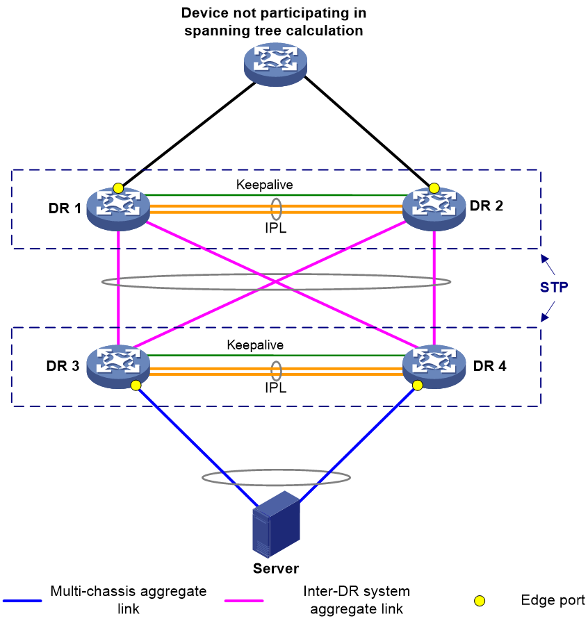
You can use DRNI in conjunction with spanning tree to remove loops, as shown in Figure 5 and Table 3.
|
Scenario |
Solution |
Commands |
|
Due to a DR system split, misconnection, or misconfiguration, traffic is sent between two member ports of the same aggregation group over the IPL, which creates a loop. |
Enable spanning tree on the DR member devices. |
stp global enable (system view) |
|
Assign the spine-facing interfaces on leaf devices to different VLANs if the leaf and spine devices are interconnected by using VLAN interfaces in an EVPN DRNI network. In addition, disable spanning tree on physical interfaces to remove loops and prevent the upstream device from falsely blocking interfaces. |
undo stp enable (Layer 2 Ethernet interface view) |
|
|
A new device added to the network preempts the root bridge role, and network flapping occurs as a result. |
Configure the DR member devices in the upstream DR system as root bridges and enable root guard on them. |
stp root primary (system view) stp root-protection (DR interface view) |
|
The DR member devices are attacked by using TC-BPDUs and flush MAC address entries frequently, which causes network flapping, high CPU usage, and transient floods. |
Enable the TC-BPDU guard feature on the DR member devices. |
stp tc-protection (system view) |
|
On a DR member device, an interface cannot recognize BPDUs after its physical state changes. |
Configure an interface as an edge port if its peer port does not support or run spanning tree protocols. |
stp edged-port (DR interface view) |
|
Network flapping occurs after a DR member device receives forged BPDUs on interfaces whose counterparts do not send BPDUs. |
Enable BPDU guard on the DR member device. When interfaces with BPDU guard enabled receive configuration BPDUs, the device performs the following operations: · Shuts down these interfaces. · Notifies the NMS that these interfaces have been shut down by the spanning tree protocol. The device reactivates the interfaces that have been shut down when the port status detection timer expires. |
stp bpdu-protection (system view) |
Restrictions and guidelines
Make sure the DR member devices in a DR system have the same spanning tree configuration. Violation of this rule might cause network flapping. The configuration includes:
· Global spanning tree configuration.
· Spanning tree configuration on the IPP.
· Spanning tree configuration on DR interfaces.
IPPs of the DR system do not participate in spanning tree calculation.
The DR member devices still use the DR system MAC address after the DR system splits, which will cause spanning tree calculation issues. To avoid the issues, enable DRNI standalone mode on the DR member devices before the DR system splits.
Spanning tree configurations made in system view take effect globally. Spanning tree configurations made in Layer 2 Ethernet interface view take effect only on the interface. Spanning tree configurations made in Layer 2 aggregate interface view take effect only on the aggregate interface. Spanning tree configurations made on an aggregation member port can take effect only after the port is removed from its aggregation group.
After you enable a spanning tree protocol on a Layer 2 aggregate interface, the system performs spanning tree calculation on the Layer 2 aggregate interface. It does not perform spanning tree calculation on the aggregation member ports. The spanning tree protocol state and forwarding state of each selected member port are consistent with those of the corresponding Layer 2 aggregate interface. The member ports of an aggregation group do not participate in spanning tree calculation. However, the ports still reserve their spanning tree configurations for participating in spanning tree calculation after leaving the aggregation group.
DRNI and loop detection
A loop detection-enabled device detects loops by sending detection frames and then checking whether these frames return to any interface on the device. If they do, the device considers that the interface is on a looped link.
You can enable loop detection on a DR system to remove loops. As shown in Figure 6, loop detection is enabled for VLAN 100 globally or on interfaces on DR 1 and DR 2, and Device C, the DR system, Device D, and Device E form a loop. DR 1 and DR 2 can detect loops on interfaces BAGG4 and BAGG5 and remove the loops according to loop detection configuration.
Make sure the DR member devices in a DR system have the same loop detection configuration.
You can use loop detection on a DR system formed by the following device models:
· S6805.
· S6825.
· S6850.
· S9850.
· S9820-64H.
· S9820-8C.
· S12500G-AF.

Layer 3 DRNI network models
Gateway deployment schemes
Table 4 shows the schemes to configure gateways on a DR system for attached servers.
Table 4 Gateway deployment schemes for DRNI
|
Gateway type |
Description |
|
VLAN interface (recommended) |
· A VLAN interface is configured on each DR member device, and both DR member devices can respond to ARP packets and perform Layer 3 forwarding. · Attached servers require Layer 3 connectivity to the DR system in some scenarios, containers are deployed on the servers for example. To fulfil this requirement, perform one of the following tasks: ¡ Configure static routes. ¡ Assign a virtual IPv4 or IPv6 address to each gateway VLAN interface by using the port drni virtual-ip or port drni ipv6 virtual-ip command. |
|
VRRP group |
· Both the VRRP master and backup devices
perform Layer 3 forwarding, but only the master device responds to ARP
packets. · The server-side devices can set up dynamic routing neighbor relationships with the DR member devices. |
For more information about support for dual-active VLAN interfaces, see the applicable product matrix in DRNI+IPv4 and IPv6 Dual-Active VLAN Gateway Configuration Example.
The DRNI virtual IP address feature is available on the following device models and software versions:
· S12500X-AF: F2809 and later.
· S12500G-AF: R7624P12 and later.
· S6805, S6850, and S9850: F6632 and later.
· S9820-8C: F6633 and later.
Dual-active VLAN interfaces
About dual-active VLAN interfaces
Configure VLAN interfaces as gateways on both DR member devices, as shown in Figure 7 and Table 5.
For more information about configuring dual-active VLAN interfaces, see DRNI+IPv4 and IPv6 Dual-Active VLAN Gateway Configuration Example.
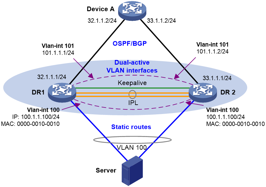
Table 5 Configuration tasks
|
Tasks |
Forwarding |
|
· VLAN interface configuration: a. Create a gateway VLAN interface on each DR member device for the same VLAN. b. Assign the same IP address and MAC address to the gateway VLAN interfaces. c. Create a VLAN interface on each DR member
device for another VLAN, assign the IPPs to this VLAN, and assign a unique IP
address from the same subnet to each of the VLAN interfaces. · Use Layer 3 interfaces to connect the DR member devices to the upstream device, and configure ECMP routes for load sharing across the uplinks. · Configure static routes for reaching the attached servers if the servers accommodate containers and the DRNI virtual IP address feature is not supported. |
· For Layer 2 traffic sent by the servers, the DR member devices look up the MAC address table and forward the traffic locally. · For Layer 3 traffic sent by the servers, the DR member devices perform Layer 3 forwarding based on the FIB table. · For external traffic destined for the servers, the DR member devices perform forwarding based on the routing table. |
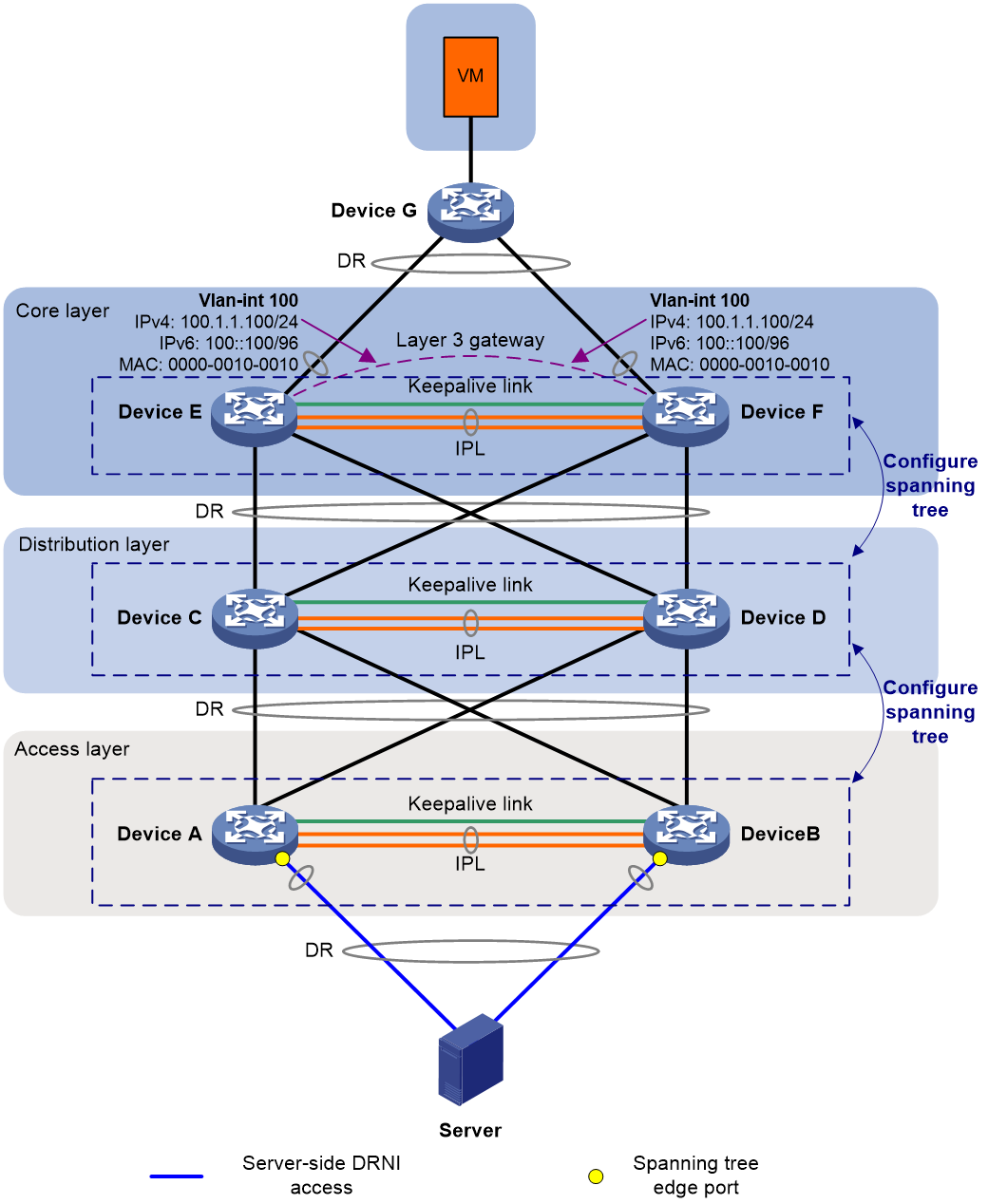
Network models for deploying dual-active VLAN interfaces on DR systems at multiple layers with core devices as gateways
As shown in Figure 8, DR systems are set up at three layers to avoid single points of failure:
· Device A and Device B form a DR system at the access layer. Device C and Device D form a DR system at the distribution layer. Device E and Device F form a DR system at the core layer.
· The server is dualhomed to the access DR system. The VM is dualhomed to the core DR system via Device G.
· Dual-active VLAN interfaces are configured on the core DR system to offer gateway and routing services.
· Spanning tree is configured on Device A through Device F, and Device E and Device F are configured as root bridges.
As shown in Figure 9, DR systems are set up at the access and distribution layers to avoid single points of failure.
DRNI deployment does not differ greatly between a three-layer network and a two-layer network. For more configuration details, see Multi-Layer DRNI+STP+Dual-Active VLAN Gateway Configuration Examples.

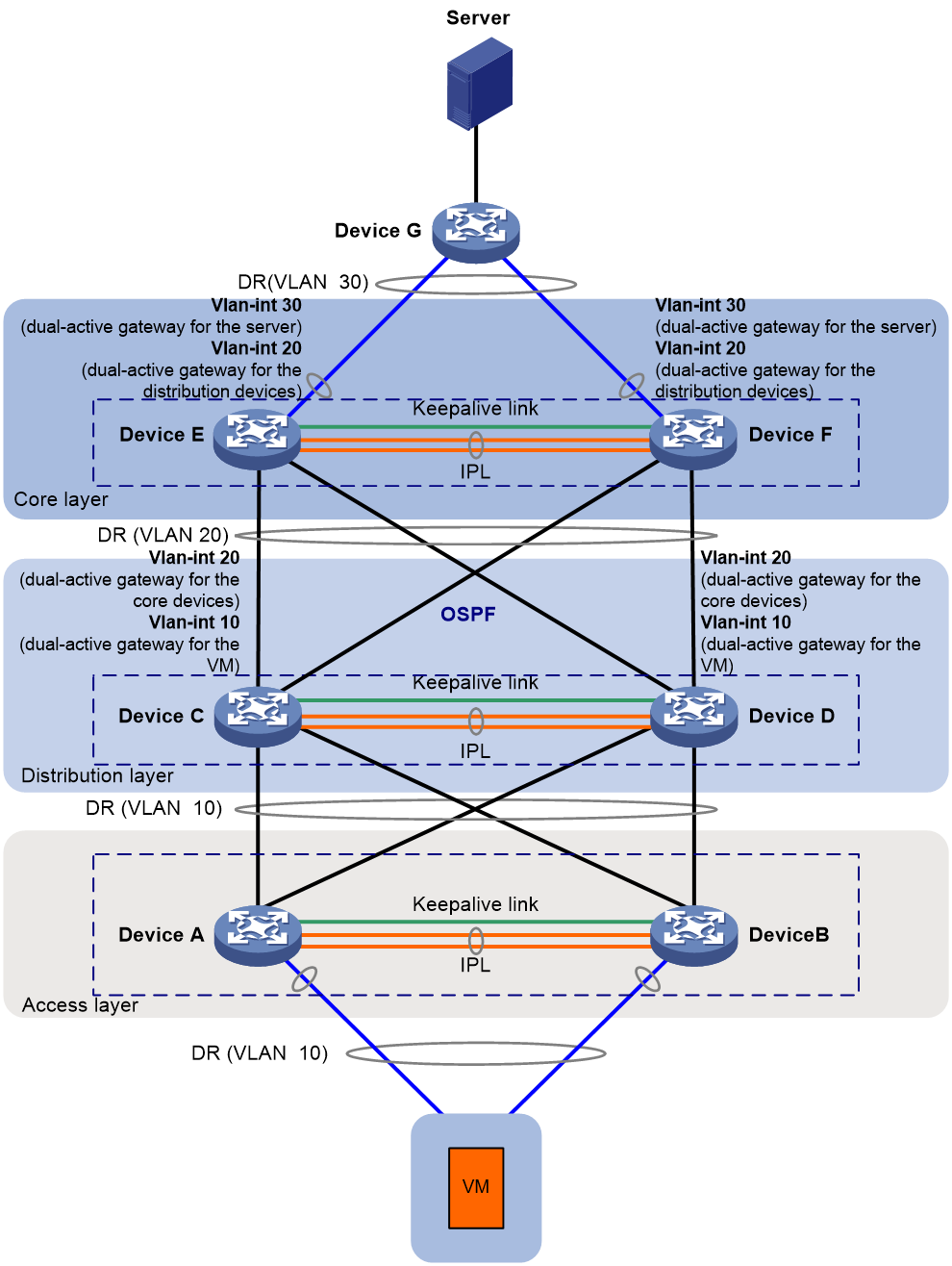
Network models for deploying dual-active VLAN interfaces on DR systems at multiple layers with distribution and core devices as gateways
As shown in Figure 10, DR systems are set up at three layers to avoid single points of failure:
· Device A and Device B form a DR system at the access layer. Device C and Device D form a DR system at the distribution layer. Device E and Device F form a DR system at the core layer.
· The server is dualhomed to the core DR system via Device G. The VM is dualhomed to the access DR system.
· Dual-active VLAN interfaces are configured on the core DR system to offer gateway and routing services to the server. Dual-active VLAN interfaces are configured on the distribution DR system to offer gateway and routing services to the VM. OSPF provides Layer 3 connectivity between the distribution and core layers.
· DRNI virtual IP addresses are configured on Device C through Device F for them to set up OSPF neighbor relationships.
For more configuration details, see Multi-Layer DRNI+Dual-Active VLAN Gateway+OSPF Configuration Examples.
|
Interface |
IP address |
|
|
Device C Device D |
Vlan-int10 |
IPv4: 10.1.1.1/24 IPv6: 10:1::1/64 |
|
Vlan-int20 |
IPv4: 20.1.1.1/24 Device C's DRNI virtual IPv4 address: 20.1.1.103/24 Device D's DRNI virtual IPv4 address: 20.1.1.104/24 IPv6: 20:1::1/64 Device C's DRNI virtual IPv6 address: FE80::6 Device D's DRNI virtual IPv6 address: FE80::8 |
|
|
Device E Device F |
Vlan-int20 |
IPv4: 20.1.1.2/24 Device E's DRNI virtual IPv4 address: 20.1.1.101/24 Device F's DRNI virtual IPv4 address: 20.1.1.102/24 IPv6: 20:1::2/64 Device E's DRNI virtual IPv6 address: FE80::2 Device F's DRNI virtual IPv6 address: FE80::4 |
|
Vlan-int30 |
IPv4: 30.1.1.1/24 IPv6: 30:1::1/64 |
Restrictions and guidelines
To ensure correct ND entry synchronization, execute the ipv6 nd unsolicited-na-learning enable command on the IPv6 dual-active VLAN interfaces.
Routing neighbor relationship setup on dual-active VLAN interfaces using DRNI virtual IP addresses
For the gateway VLAN interfaces to establish routing neighbor relationships with a server-side network device, perform the following tasks:
· Assign a virtual IPv4 or IPv6 address to each gateway VLAN interface by using the port drni virtual-ip or port drni ipv6 virtual-ip command.
· Configure routing protocols.
The gateway VLAN interfaces will use the virtual IP addresses to establish routing neighbor relationships.
Use this scheme if the servers accommodate containers.
Figure 11 Network diagram

Table 6 Configuration tasks
|
Scenario |
Tasks |
Forwarding |
|
The servers attached to the DR system accommodate containers, and a dynamic routing protocol runs between the DR system and the servers. |
· VLAN interface configuration: a. Create a gateway VLAN interface on each DR member device for the same VLAN. b. Assign the same IP address and MAC address to the gateway VLAN interfaces. c. Assign a unique virtual IP address from
the same subnet to each of the gateway VLAN interfaces. d. Create a VLAN interface on each DR member
device for another VLAN, assign the IPPs to this VLAN, and assign a unique IP
address from the same subnet to each of the VLAN interfaces. · Create a VLAN interface on each DR member
device for another VLAN, assign the IPPs to this VLAN, and assign a unique IP
address from the same subnet to each of the VLAN interfaces. · Use Layer 3 interfaces to connect the DR member devices to the upstream device, and configure ECMP routes for load sharing across the uplinks. |
· For Layer 2 traffic sent by the servers, the DR member devices look up the MAC address table and forward the traffic locally. · For Layer 3 traffic sent by the servers, the DR member devices perform Layer 3 forwarding based on the FIB table. · For external traffic destined for the servers, the DR member devices perform forwarding based on the routing table. |
|
BFD is required. |
Configure the DR member devices to use the DRNI virtual IP addresses to set up BFD sessions with the secondary IP address of the gateway VLAN interface on the server-side network device. |
N/A |
For more configuration details, see DRNI+IPv4 and IPv6 Dual-Active VLAN Gateway Configuration Example.
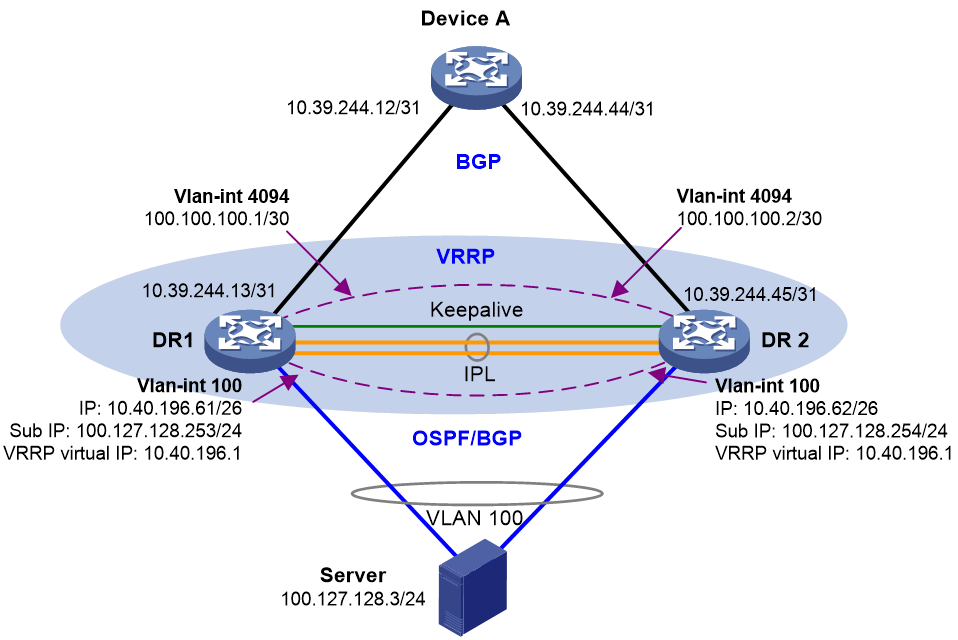
VRRP gateways
Network model
You can configure VRRP groups on a DR system to provide gateway services for the attached servers, as shown in Figure 12 and Table 7.
For more configuration details, see DRNI and VRRP Configuration Example.
|
Tasks |
Forwarding |
|
· Configure a VRRP group on the DR member devices and use the VRRP virtual IP address as the gateway for the attached servers. · VLAN interface configuration: a. Create a VLAN interface for the VLAN where the DR interface resides on each DR member device. b. Assign a unique primary IP address from one subnet to each of the VLAN interfaces. c. Assign a unique secondary IP address from another subnet to each of the VLAN interfaces. · Use the primary or secondary IP addresses of the VLAN interfaces to set up BGP or OSPF neighbor relationships with the server-side network device. Perform this task if the servers accommodate containers. · Set up a Layer 3 connection over the IPL
between the DR member devices. · Use Layer 3 interfaces to connect the DR member devices to the upstream device, and configure ECMP routes for load sharing across the uplinks. |
· For the Layer 3 traffic sent by the servers, both DR member devices can perform forwarding. · For the external traffic destined for the servers, the DR member devices make forwarding decisions based on local routes. |
Restrictions and guidelines
Both VRRP standard mode and load balancing mode are supported. VRRP standard mode also supports load sharing on a DR system. Use VRRP standard mode as a best practice.
If you use DRNI and VRRP together, make sure the keepalive hold timer is shorter than the interval at which the VRRP master sends VRRP advertisements. Violation of this restriction might cause a VRRP master/backup switchover to occur before IPL failure is acknowledged. To set the interval at which the VRRP master sends VRRP advertisements, use the vrrp vrid timer advertise command or the vrrp ipv6 vrid timer advertise command. To set the keepalive hold timer, use the drni keepalive hold-time command.
To avoid frequent master/backup switchovers, configure the routers in a VRRP group to operate in non-preemptive mode.
For the S12500X-AF H card series, a device supports 15 VRRP group IDs in VRRP standard mode and 7 VRRP group IDs in VRRP load balancing mode. As a best practice, configure the same VRRP group ID for multiple Layer 3 interfaces to save VRRP group IDs. If a device fails to issue a VRRP group to a VLAN interface because of VRRP group ID exhaustion, delete other VRRP groups, delete the VRRP group configuration to issue, and then reconfigure the VRRP group.
The S12500G-AF, S6805, S6825, S6850, S9850, S9820-64H, S9820-8C, S6800, and S6860 switches support a maximum of 256 VRRP groups, and each interface supports a maximum of 32 VRRP groups. As a best practice, configure the same VRRP group ID for multiple Layer 3 interfaces to save VRRP group IDs.
The S6812 and S6813 switches support a maximum of 255 VRRP groups, and each interface supports a maximum of 16 VRRP groups. As a best practice, configure the same VRRP group ID for multiple Layer 3 interfaces to save VRRP group IDs.
Restrictions and guidelines for single-homed servers attached to non-DR interfaces
Dual-active VLAN interfaces
If a server is single-homed to a DR system or its NICs operate in active/standby (bond1) mode, perform the following tasks to ensure correct traffic forwarding:
1. Create an aggregate interface. For the S6805, S6825, S6850, S9850, S9820-64H, and S9820-8C switches running R6635, you do not need to assign physical interfaces to the related aggregation group. In other scenarios, assign up physical interfaces to the aggregation group to prevent DRNI MAD from falsely shutting down the not rebooted secondary device after the primary device reboots.
2. Assign the aggregate interface to all VLANs where the server resides.
3. Assign the aggregate interface to a DR group.
VRRP gateways
If the NICs of a server operate in active/standby (bond1) mode, perform the following tasks to ensure correct traffic forwarding:
1. Create an aggregate interface. For the S6805, S6825, S6850, S9850, S9820-64H, and S9820-8C switches running R6635, you do not need to assign physical interfaces to the related aggregation group. In other scenarios, assign up physical interfaces to the aggregation group to prevent DRNI MAD from falsely shutting down the not rebooted secondary device after the primary device reboots.
2. Assign the aggregate interface to the VLAN where the VRRP gateway resides.
3. Assign the aggregate interface to a DR group.
Only a VRRP master can learn the ARP entries for single-homed servers. A VRRP backup can learn ARP entries for single-homed servers only when it needs to send ARP requests to the single-homed servers after receiving certain packets, and transient traffic loss might occur as a result.
Restrictions and guidelines for routing configuration
Router ID
You must manually assign unique router IDs to the DR member devices in a DR system. If you use EVPN and DRNI together, perform the following tasks:
· On each DR member device, use loopback 0 to provide the local VTEP address and router ID. You must assign different IP addresses to loopback 0 on the DR member devices.
· On each DR member device, use loopback 1 to provide the virtual VTEP address. You must assign the same IP address to loopback 1 on the DR member devices.
To configure the virtual VTEP address, use the evpn drni group command.
NSR
You must enable NSR for the routing protocol used on DR member devices that have two MPUs.
OSPF and OSPFv3
For fast network convergence, perform the following tasks on all devices with OSPF or OSPFv3 configured:
· Execute the ospf network-type p2p or ospfv3 network-type p2p command on the interfaces that have OSPF or OSPFv3 neighbors.
· Execute the spf-schedule-interval 1 10 10 and lsa-generation-interval 1 10 10 commands in OSPF or OSPFv3 view to speed up SPF calculation and LSA generation after link failure occurs.
· Accelerate network convergence after a device reboots:
¡ In OSPF view, execute the stub-router include-stub on-startup command. For a fixed-port device, set this timeout time to 300 seconds. For a modular device, set the timeout time to be longer than 300 seconds. If all slots of a modular device have modules installed, set the timeout time to 900 seconds or longer.
¡ In OSPFv3 view, execute the stub-router max-metric include-stub on-startup command. For a fixed-port device, set this timeout time to 300 seconds. For a modular device, set the timeout time to be longer than 300 seconds. If all slots of a modular device have modules installed, set the timeout time to 900 seconds or longer.
DRNI and RDMA
Network model
As shown in Figure 13, you can set up DR systems with leaf devices in an RDMA network for the servers to be dual-homed to the network. The redundant links between a DR system and an attached server are aggregated for high availability and traffic load sharing.
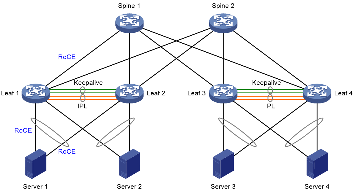
Table 8 Configuration tasks
|
Tasks |
Forwarding |
|
· For server uplink redundancy and traffic load sharing, set up one DR system with Leaf 1 and Leaf 2, and set up another DR system with Leaf 3 and Leaf 4. · For gateway redundancy and traffic load sharing, configure dual-active VLAN gateways or VRRP groups on the DR systems. · Configure the spine devices at the distribution layer as RRs to reflect BGP routes among the leaf devices. · Configure the lossless network as follows on the server-facing physical interfaces of the leaf devices and the physical interfaces interconnecting the leaf and spine devices: a. Enable PFC and set the PFC threshold for lossless queues to implement priority-based flow control. b. Configure PFC deadlock detection to prevent the devices from entering PFC deadlock state when forwarding paths are looped for packets with a specific priority. c. Configure QoS queue scheduling to prioritize traffic forwarding for lossless queues and CNP queues. d. Configure WRED to avoid congestion. Configure ECN for lossless queues and CNP queues for end-to-end congestion control. · Adjust the data buffer settings for lossless queues on the leaf devices, including the maximum Headroom buffer size and maximum outbound shared-area space. · For traffic to fail over through the IPL in case of uplink failure, configure Monitor Link on the DR member devices in the same DR system, or configure the devices to set up routing neighbor relationships with each other on VLAN interfaces. |
· For Layer 2 traffic sent between the downstream servers attached to the same DR system, the DR member devices look up the MAC address table and forward the traffic locally. · For Layer 3 traffic sent by a server, the upstream DR member devices perform Layer 3 forwarding over the ECMP links towards the spine devices. The spine devices will forward the traffic towards the destination server attached to another DR system. · For external traffic destined for a server, the upstream DR member devices perform forwarding based on the routing table. · Traffic traversing each DR system is load shared across the uplinks and downlinks. · Traffic loss does not occur when the traffic sent between two servers attached to the same DR system or different DR systems is congested. |
For more configuration details, see DRNI and RDMA Configuration Example.
Restrictions and guidelines
Configure the following features on the physical interfaces used as IPPs:
· Configure QoS queue scheduling to prioritize traffic forwarding for lossless queues and CNP queues.
· Configure WRED to avoid congestion.
DRNI and EVPN
You can set up a DR system with two leaf or border devices in an EVPN network to prevent single points of failure from interrupting servers. For more information about EVPN overlay network planning, see "Overlay network planning." This section uses a three-tiered network as an example.
You can deploy distributed or centralized gateways in the network. If you use distributed gateways, all leaf devices can act as VXLAN IP gateways to forward Layer 3 traffic locally. If you use a centralized gateway, it forwards all traffic sent between VXLANs and from the VXLANs to external networks. The traffic load on the centralized gateway is heavier than on a distributed gateway.
As a best practice, use an Ethernet aggregate interface as an IPL. Do not use a VXLAN tunnel as an IPL.
Distributed gateway deployment
Figure 14 Network diagram

Table 9 Configuration tasks
|
Tasks |
Forwarding |
|
· Configure the leaf devices as VTEPs or EVPN gateways to forward Layer 2 and Layer 3 traffic among the servers. · Set up DR systems at the leaf tier and attach each server to two DR member devices in the same DR system. · Configure the spine devices (not DR member devices) as RRs to reflect routes between the leaf and border tiers. · Configure the border devices as EDs to set up VXLAN-DCI tunnels to other data centers. · Set up a DR system at the border tier for reliable access to external networks. |
For the Layer 2 and Layer 3 traffic sent by the servers, the leaf devices forward it over VXLAN tunnels to the destination servers or towards the border devices. The border devices look up the routing table to forward the traffic destined for the external networks. The DR member devices in a DR system use the virtual VTEP IP address to set up VXLAN tunnels, and they use their real IP addresses to establish BGP peer relationships with the spine devices. For load sharing and high availability, traffic destined for the virtual VTEP IP address is distributed over the underlay network to both DR member devices based on ECMP routes. |
For more configuration details, see DRNI and EVPN Distributed Gateway Configuration Example.
Centralized gateway deployment
Figure 15 Network diagram
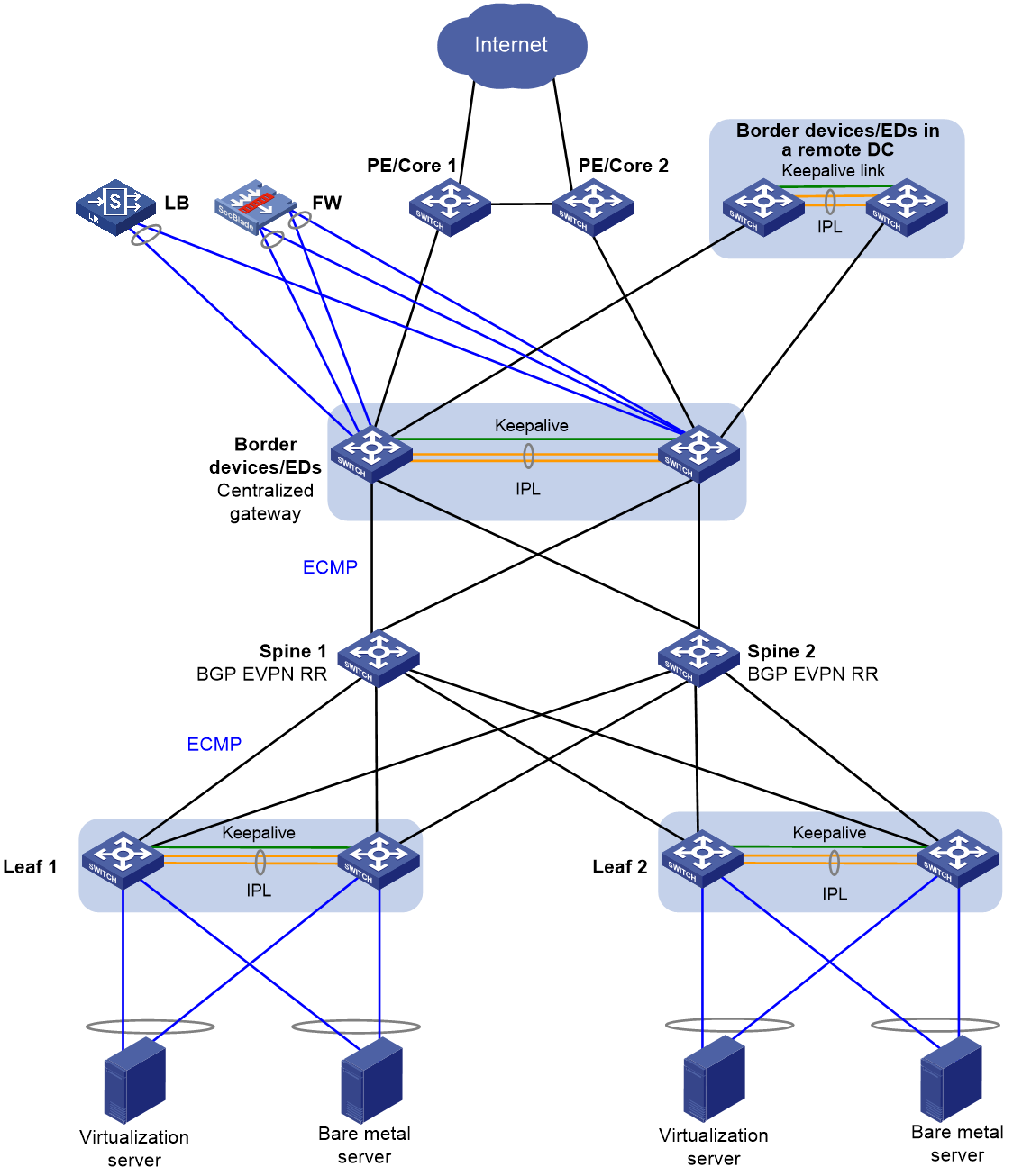
Table 10 Configuration tasks
|
Tasks |
Forwarding |
|
· Configure the leaf devices as VTEPs to forward Layer 2 traffic among the servers. · Set up DR systems at the leaf tier and attach each server to two DR member devices in the same DR system. · Configure the spine devices (not DR member devices) as RRs to reflect routes between the leaf and border tiers. · Set up a DR system at the border tier for reliable access to external networks. · Configure centralized gateway interfaces on the DR system. · Configure the border devices as EDs to set up VXLAN-DCI tunnels to other data centers. |
For the Layer 2 traffic sent by the servers, the leaf devices forward it over VXLAN tunnels to the destination servers. For the Layer 3 traffic sent by the servers, the leaf devices forward it towards the border devices. The border devices look up the routing table to forward the traffic destined for the external networks or another server at Layer 3. The DR member devices in a DR system use the virtual VTEP IP address to set up VXLAN tunnels, and they use their real IP addresses to establish BGP peer relationships with the spine devices. For load sharing and high availability, traffic destined for the virtual VTEP IP address is distributed over the underlay network to both DR member devices based on ECMP routes. |
For more configuration details, see DRNI and EVPN Distributed Gateway (IS-IS for underlay routing) Configuration Example and DRNI and EVPN Distributed Gateway (BGP for Underlay Routing) Configuration Example.
Failover between data centers
If the links to external network fail or the local border devices fail in a data center, traffic exchanged between internal and external networks can fail over to the border devices in a backup data center. DRNI+EVPN DC Switchover Upon Border Failure Configuration Examples introduces configuration details for border devices that use DR interfaces and Layer 3 Ethernet interfaces to connect external networks. Traffic fails over to a backup data center when one of the following events occurs on the border devices.
· All member ports of a DR interface go down. In this scenario, only traffic on that DR interface fails over to a backup data center.
· All spine-facing interfaces go down on both border devices.
· Both border devices fail.
|
|
NOTE: Failure handling mechanisms for DR interfaces, IPL, keepalive link, and transport-facing interfaces on a single border device and recovery of a single border device have been introduced in EVPN and DRNI configuration examples. |
Basic configuration restrictions and guidelines
Network setup
· In a DR system, DR member devices such as VTEPs or EVPN gateways must have the same EVPN configuration, including:
¡ ACs.
¡ VSI-to-VXLAN mappings.
¡ EVPN router MAC address. You can use one of the following methods to configure the EVPN router MAC address:
- Use the evpn global-mac command to configure the EVPN global MAC address.
- Use the mac-address command to assign a MAC address to a VSI interface with a L3VNI configured.
· Do not use VSI-interface 0 as a distributed EVPN gateway.
· For a DR member device to re-establish VXLAN tunnels, you must execute the address-family l2vpn evpn command in BGP instance view after you enable or disable DRNI.
· You cannot specify a secondary IP address of an interface as the virtual VTEP address.
· You must execute the undo mac-address static source-check enable command on the Layer 2 aggregate interfaces that act as IPPs and transport-facing physical interfaces. This restriction does not apply to S12500X-AF, S12500G-AF, or S6890 switches.
· For the S6805, S6825, S6850, or S9850 switches, make sure the underlay network and the virtual VTEP address are the same IP version. IP version inconsistency will cause VXLAN tunnel setup failure.
· As a best practice, do not redistribute external routes on the DR member devices.
ACs
If an Ethernet aggregate link is used as the IPL, follow these restrictions:
· If the frame match criteria of dynamic ACs on the IPL are created based on site-facing Ethernet service instances, you can configure only the following criteria for site-facing Ethernet service instances:
¡ encapsulation s-vid { vlan-id | vlan-id-list }
¡ encapsulation untagged
In addition, you must set the access mode to VLAN for the site-facing Ethernet service instances. Ethernet service instances with the same frame match criterion configured must be mapped to the same VSI.
· When the frame match criteria of dynamic ACs on the IPL are created based on VXLAN IDs, you must set the access mode to VLAN for the site-facing Ethernet service instances. To match double-tagged VLAN packets on an Ethernet service instance, you must configure the encapsulation s-vid vlan-id-list c-vid vlan-id-list criterion. If you use the encapsulation s-vid { vlan-id | vlan-id-list } criterion to match multi-tagged packets, packets forwarded over the IPL might carry incorrect VLAN tags.
Whether these restrictions apply to S6812 and S6813 switches is to be verified.
· If the traffic outgoing interface for a VXLAN tunnel is a DR interface, do not assign the DR interface to a VLAN matched by an Ethernet service instance on the IPL.
IPL
· As a best practice, set the PVID to 4094 on the IPPs. If you fail to do so and also execute the l2vpn drni peer-link ac-match-rule vxlan-mapping command, a DR member device might set the outer VLAN ID matched by an AC to the PVID of its IPP. This issue will affect forwarding of the underlay traffic whose VLAN ID is VXLAN ID%4094 + 1.
· The DR member devices synchronize with each other their MAC address, ARP, and ND entries learned on local AC interfaces over the IPL.
· For the DR system to correctly forward traffic for single-homed devices, set the link type to trunk for the IPPs and the non-DR interfaces attached to the single-homed devices. If you fail to do so, the ND protocol packets sent to or from the single-homed devices cannot be forwarded over the IPL. This restriction does not apply to S12500G-AF, S6812, or S6813 switches.
Miscellaneous
· Assign the spine-facing interfaces on leaf devices to different VLANs if the leaf and spine devices are interconnected by using VLAN interfaces in an EVPN DRNI network. In addition, disable spanning tree on physical interfaces to remove loops and prevent the upstream device from falsely blocking interfaces.
· Configure backup routes for directing traffic from one DR member device to the other DR member device upon uplink failure.
· If the IPL or an AC forwards both overlay and underlay traffic, the IPP or the site-facing interface that hosts the AC might reflect back received packets. To resolve this issue, assign the IPP or site-facing interface to a port isolation group to disable it from reflecting packets back. If the interface is an aggregate interface, it will not reflect back the packets received by a member port. This restriction applies to the following switches:
¡ S6800-32Q (LS-6800-32Q-H1)
¡ S6800-54HF
¡ S6800-54HT
¡ S6800-2C (LS-6800-2C-H1)
¡ S6800-2C-FC
¡ S6800-4C (LS-6800-4C-H1)
¡ S6800-54QF (LS-6800-54QF-H3)
¡ S6800-54QT (LS-6800-54QT-H3)
Restrictions and guidelines for IPL ACs
As a best practice, enable frame match criteria creation based on VXLAN IDs for the dynamic ACs on the IPL if you use the S12500G-AF, S6800, S6860, S6812, S6813, S6805, S6825, S6850, and S9850 switches. This feature is configurable with the l2vpn drni peer-link ac-match-rule vxlan-mapping command. Make sure the highest VXLAN ID is not larger than 16000000.
If you use the S12500X-AF or S6890 switches, use the l2vpn drni peer-link tunnel command to enable the switches to automatically set up a VXLAN tunnel with a DR peer. After you execute this command, the DR member devices no longer create dynamic ACs on the IPL. Instead, they set up a VXLAN tunnel and assign it to all VXLANs. The forwarding entries synchronized between the DR member devices will be associated with the related VXLAN tunnel interfaces.
If neither frame match criteria creation based on VXLAN IDs (l2vpn drni peer-link ac-match-rule vxlan-mapping) nor automatic VXLAN tunnel setup (l2vpn drni peer-link tunnel) is enabled, and an Ethernet aggregate link is used as the IPL, the DR member devices by default automatically create ACs on the IPL based on site-facing ACs. The IPL ACs and the site-facing ACs have the same frame match criteria. In this scenario, Ethernet service instances matching the same outer VLAN ID must be mapped to the same VSI.
MAC address configuration restrictions and guidelines
Distributed EVPN gateways use the following VSI interfaces to perform Layer 3 forwarding:
· VSI interfaces acting as distributed gateway interfaces. Their MAC addresses are used as gateway addresses in VXLANs.
· VSI interfaces with an L3VNI and a VPN instance associated. Their MAC addresses are encapsulated as the inner source MAC addresses in the Layer 3 packets sent between gateways. These MAC addresses are known as router MAC addresses.
Do not assign the same MAC address to VSI interfaces of different types.
MAC address configuration for L3VNI associated VSI interfaces
· You can use one of the following methods to assign MAC addresses to L3VNI associated VSI interfaces:
¡ Use the evpn global-mac command to configure an EVPN global MAC address for all L3VNI associated VSI interfaces on a device. This method is recommended.
¡ Use the mac-address command to assign MAC addresses on a per-VSI interface basis.
· A distributed EVPN gateway selects the lowest-numbered L3VNI associated VSI interface to provide the router MAC address. In a DR system, distributed EVPN gateways that act as DR member devices must use the same router MAC address. As a best practice, assign the same MAC address to the L3VNI associated VSI interfaces.
· Configure the same EVPN global MAC address on the DR member devices in a DR system. Make sure the EVPN global MAC address of a DR system is unique in the local data center and the remote data centers connected to the local data center through DCI tunnels.
· As a best practice, use one of the following methods to configure the EVPN global MAC address on a DR system formed by the S6805, S6825, S6850, S9850, S6800, S6860, or S12500G-AF switches:
¡ Use the default MAC address of a Layer 3 Ethernet interface on a DR member device as the EVPN global MAC address. This method is recommended.
¡ Use an available unicast MAC address in the range of 0001-0001-0001 to 0001-0001-FFFE as the EVPN global MAC address.
For information about EVPN global MAC address configuration on S12500X-AF switches, see "MAC address assignment for the S12500X-AF switches." For information about EVPN global MAC address configuration on S6890 switches, contact H3C Support.
· If you use the mac-address command to modify the MAC address of a L3VNI associated VSI interface on a DR system, also modify the MAC address of the other L3VNI associated VSI interfaces. These VSI interfaces must use the same MAC address.
· If a distributed EVPN gateway is connected to an IPv6 site, make sure the L3VNI associated VSI interfaces use the same link-local address.
MAC address configuration for distributed gateway interfaces
· On different distributed EVPN gateways, the VSI interface of a VXLAN must use the same IP address and MAC address to provide services.
· Do not assign reserved MAC addresses to VSI interfaces. For more information about reserved MAC addresses, see the configuration guides for the devices you use.
Leaf device configuration restrictions and guidelines
Execute the evpn drni local command. If single-homed ACs are attached to a DR system, a VTEP uses the source IP address of the IPL as the next hop of routes for single-homed ACs to ensure correct traffic forwarding.
Execute the vxlan default-decapsulation command. If a VXLAN tunnel is configured on only one device in a pair of devices, the VXLAN tunnel is a unidirectional tunnel to the device not configured with the tunnel. For a DR member device to receive VXLAN packets from a unidirectional VXLAN tunnel, enable default VXLAN decapsulation for the interface whose IP address is the tunnel destination address. The DR member device will decapsulate all the VXLAN packets destined for the IP address of that interface. This feature takes effect only when the specified interface has an IP address.
Execute the l2vpn drni peer-link ac-match-rule vxlan-mapping command on the S12500G-AF, S6800, S6860, S6812, S6813, S6805, S6825, S6850, and S9850 switches.
Border and ED configuration restrictions and guidelines
Execute the nexthop evpn-drni group-address command. After you execute this command, a DR member device changes the next hop in advertised EVPN routes to the DRNI virtual IP address. The traffic destined for the DRNI virtual IP address will be distributed to both DR member devices based on the ECMP routes on the underlay network.
Do not execute the evpn drni local command on border devices, even when single-homed devices exist. If you do so, the nexthop evpn-drni group-address command does not take effect.
Restrictions and guidelines for server access in active/standby mode
If all servers are attached to a DR system in bond1 node and NIC preemption is enabled, create a DR group for DRNI MAD to take effect and for fast convergence after a device reboot or IPL down event. For the S6805, S6825, S6850, S9850, S9820-64H, and S9820-8C switches running R6635, you do not need to assign physical interfaces to the related aggregation group. In other scenarios, assign up physical interfaces to the aggregation group to prevent DRNI MAD from falsely shutting down the not rebooted secondary device after the primary device reboots.
This restriction does not apply if all servers are attached to a DR system in bond1 node with NIC preemption disabled.
Routing neighbor relationship setup on a DR system formed by distributed EVPN gateways
If you set up a DR system with distributed EVPN gateways, you must assign the same IP and MAC addresses to the VSI interfaces that provide gateway services for the same subnet. For the DR member devices to set up routing neighbor relationships with server-side network devices, assign unique DRNI virtual IP addresses to the VSI interfaces by using the port drni virtual-ip or port drni ipv6 virtual-ip command. The DR member devices will use the DRNI virtual IP addresses to set up routing neighbor relationships with the server-side network devices. If the servers send Layer 3 traffic sourced from container nodes, the server-side network devices forward the traffic to the DR system based on the routes generated for the routing neighbor relationships, as shown in Figure 16.
|
|
NOTE: For support of VSI interfaces for DRNI virtual IP addresses in this application scenario and configuration details, see Access to DRNI Through Dynamic Routing and Distributed EVPN Gateways Configuration Example. |
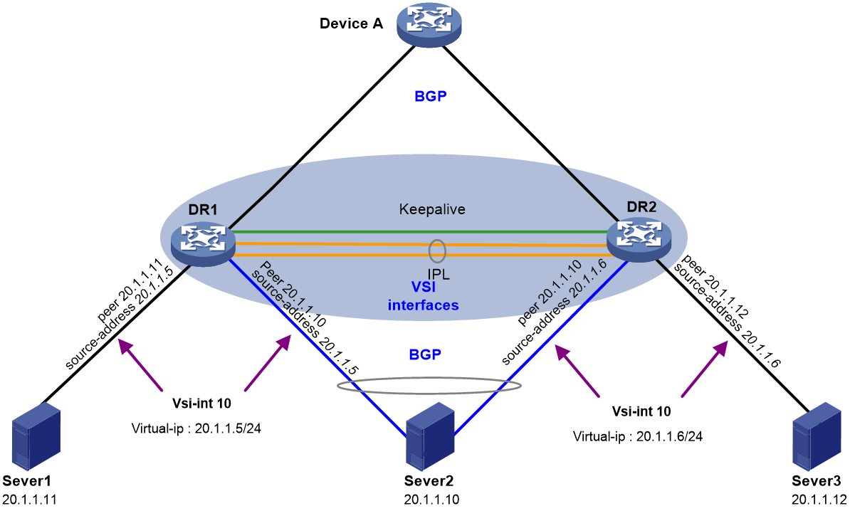
Table 11 Configuration tasks
|
Tasks |
Forwarding |
|
· Create a VSI interface with the same number on each DR member device as the gateways for a subnet. · Assign the same gateway IP address to the VSI interfaces. · Assign different DRNI virtual IP addresses to the VS interfaces. |
· For the Layer 2 and Layer 3 overlay traffic sent by the servers, the DR member devices perform forwarding based on the MAC address entries and FIB entries. · For the external traffic destined for the servers, the DR member devices perform forwarding based on the routes generated for the routing neighbor relationships with the server-side network devices. |
DRNI, EVPN, and DHCP relay
About this deployment scheme
You can use both EVPN and DHCP relay on a DR system. As shown in Figure 17, the leaf-tier DR systems are formed by distributed EVPN gateways, and the DHCP server and DHCP client reside in different subnets that belong to two VXLANs. The DHCP client can obtain an IP address from the DHCP server through DHCP relay. The DHCP server and client are unaware of the overlay network.
Both DHCPv4 relay and DHCPv6 relay are supported on a DR system, and the DR member devices in a DR system must have the same DHCP relay configuration.
As a best practice, use a dedicated DHCP server instead of one collocated with a switch. The collocation scheme degrades the performance of a switch.
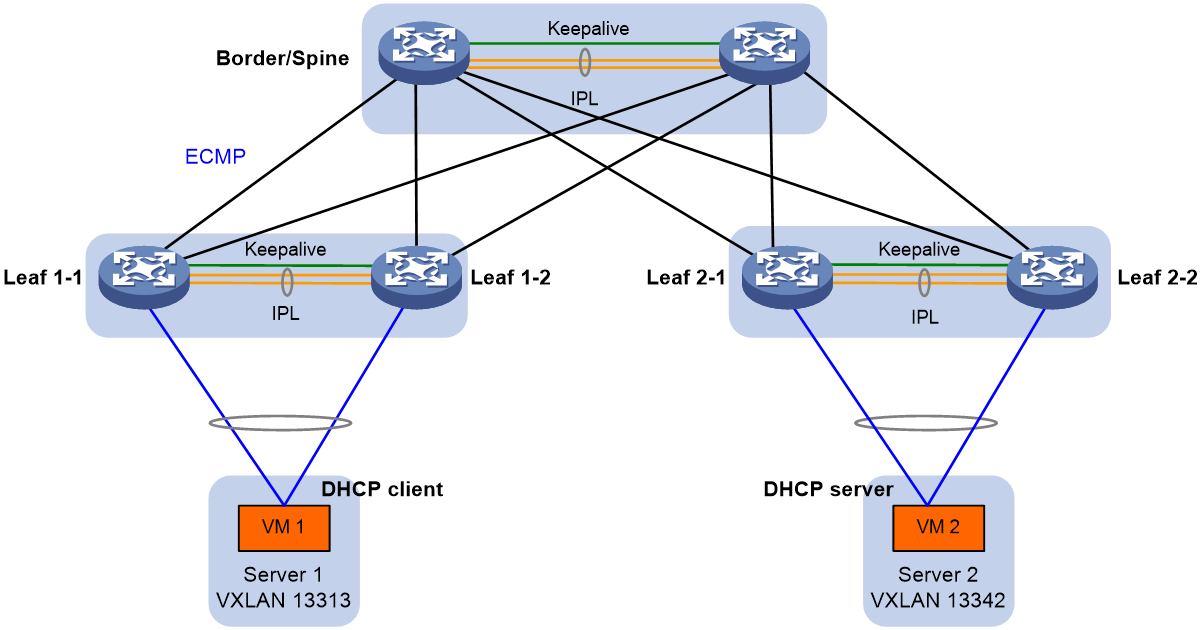
Table 12 Configuration tasks
|
Tasks |
Forwarding |
Remarks |
|
· Set up two DR systems at the leaf tier. · Attach the DHCP server and DHCP client to their local DR systems with one or two links. · Configure distributed EVPN gateway and DHCP relay settings on the DR systems. |
· A DHCP request sent from the DHCP client to the DHCP server is forwarded as follows: a. Leaf 1-1 or Leaf 1-2 selects a DHCP server, encapsulates the DHCP request, and forwards it over a VXLAN tunnel towards the DHCP server. b. Leaf 2-1 or Leaf 2-2 decapsulates the DHCP request and forwards it to the DHCP server. · A DHCP relay sent from the DHCP server to the DHCP client is forwarded as follows: a. Leaf 2-1 or Leaf 2-2 encapsulates the DHCP reply and forwards it over a VXLAN tunnel towards the DHCP client. b. Leaf 1-1 or Leaf 1-2 decapsulates the DHCP reply and forwards it to the DHCP client. If multiple DR systems are deployed on the route between the DHCP server and DHCP client, the DR systems forward a DHCP reply hop by hop to the gateway for the DHCP client. When a large number of endpoints access the network simultaneously, DHCP packets will surge. As a result, some endpoints might fail to obtain IP addresses immediately after requests are sent. |
You must configure DHCP relay on the leaf devices attached to the DHCP client. If you do not know the location of the DHCP client, configure DHCP relay on all leaf devices. If leaf devices provide both distributed EVPN gateway and DHCP relay services, you must perform the following steps: · Execute the dhcp relay mac-forward enable command to enable MAC address table lookup for DHCP replies that do not have request forwarding information. · Execute the dhcp relay request-from-tunnel discard command on the VSI interfaces that act as DHCP relay agents to discard the DHCP requests received from VXLAN tunnels. This feature prevents the DHCP server from receiving the same DHCP request from the relay agents on different leaf devices. |
For more configuration details, see DRNI+EVPN Distributed Gateway (OSPF on Underlay Network)+DHCP Relay+Microsegmentation+Service Chain Configuration Example.
Restrictions and guidelines
In a distributed EVPN gateway network, the replies from the DHCPv6 server must carry client MAC address information for DHCPv6 reply forwarding based on MAC address table to take effect. To meet this requirement, use the ipv6 dhcp relay interface-id user mac command. This command enables the DHCPv6 relay agent to insert client MAC addresses into Option 18 for DHCPv6 requests. Then, the replies from the DHCPv6 server will carry client MAC address information.
DRNI does not support the following DHCP relay features:
· Relay entry recording by the relay agent.
· DHCP relay agent and DHCP server proxy.
· Client offline detection.
EVPN DRNI, microsegmentation, and service chain
Network model
To simplify O&M and implement security protection, you can use microsegments to isolate users of different subnets and control traffic on a per-user group basis in an EVPN network with distributed gateways deployed. To filter and protect service traffic, you can deploy service chains to direct service traffic to traverse a series of service nodes in turn, firewall nodes for example.

Table 13 Configuration tasks
|
Tasks |
Forwarding |
|
· Set up three DR systems with the following devices to ensure availability of the network: ¡ Service Leaf 1 and Service Leaf 2. ¡ Leaf 3 and Leaf 4. ¡ Leaf 5 and Leaf 6. · Configure Spine A and Spine B as RRs to reflect routes between the leaf and borer tiers, and configure them to forward underlay traffic. · Set up a DR system with Border 1 and Border 2, borer devices of the fabric. Aggregate the uplinks to the external devices through DRNI, and use Layer 3 Ethernet interfaces to connect the downstream spine devices. · Configure microsegments on the leaf and border devices to isolate and protect users on different subnets. · Configure service chains on the leaf and border devices to direct service traffic processing. |
· For the service packets received from an AC, a leaf device matches them to ACLs to allocate them to a microsegment. · For north-south service traffic, a leaf device specifies the next hop as the IP address of the NS firewall and adds a service chain ID. For east-west service traffic, a leaf device specifies the next hop as the IP address of the EW firewall and adds a service chain ID. · The service leaf devices forward service traffic to the NS and EW firewalls based on the service ID for filtering and protection. · After processed by the NS and EW firewalls, service traffic is forwarded back to the leaf devices based on configured routes. The leaf devices then forward the service traffic to their local sites. |
For more configuration details, see DRNI+EVPN Distributed Gateway (OSPF on Underlay Network)+DHCP Relay+Microsegmentation+Service Chain Configuration Example.
DRNI and underlay multicast
You can attach Layer 2 or Layer 3 multicast sources or receivers to a DR system to prevent single points of failure from interrupting multicast forwarding.
The following matrix shows hardware support for conjunctive use of DRNI and underlay multicast.
|
Hardware |
Software |
Reference |
|
S12500X-AF, S6890 |
Not supported |
N/A |
|
S12500G-AF |
Layer 2 multicast: R7624P12 or later Layer 3 multicast: R7624P12 or later |
See the following chapters in IP Multicast Configuration Guide of H3C S12500G-AF Switch Series Configuration Guides-R762X: · IGMP snooping configuration · PIM configuration · MLD snooping configuration · IPv6 PIM configuration |
|
S6805, S6825, S6850, S9850 |
Layer 2 multicast: R6635 (only IPv4) Layer 3 multicast: R6635 (only IPv4) |
See the following chapters in IP Multicast Configuration Guide of H3C S6805 & S6825 & S6850 & S9850 Configuration Guides-Release 66xx: · IGMP snooping configuration · PIM configuration |
|
S9820-64H, S9820-8C |
Layer 2 multicast: Not supported Layer 3 multicast: Not supported |
N/A |
|
S6800, S6860 |
Layer 2 multicast: Not supported Layer 3 multicast: Not supported |
N/A |
|
S6812, S6813 |
Layer 2 multicast: Not supported Layer 3 multicast: F6622P01 |
See the following chapters in IP Multicast Configuration Guide of H3C S6812 & S6813 Switch Series Configuration Guide-R6615Pxx: · PIM configuration · IPv6 PIM configuration |
DRNI and MVXLAN
Multicast VXLAN (MVXLAN) transmits multicast traffic from a multicast source to multicast receivers in a VXLAN or EVPN VXLAN network.
You can set up a DR system with two VTEPs or border devices in an MVXLAN network to prevent single points of failure from interrupting services. A multicast source can reside in the local data center, a remote data center, or the public network.
In a DR system, the DR member devices set up MVXLAN tunnels that use the virtual VTEP address as the multicast source and the default group address as the destination. The DR member devices synchronize multicast traffic and multicast join requests (IGMP membership reports or PIM join messages) over the IPL to maintain consistency in multicast source and receiver information. When one DR member device fails or its uplink or downlink fails, the other DR member device forwards all multicast traffic to avoid traffic interruption.
|
|
NOTE: For more information about support for MVXLAN and configuration details, see DRNI and MVXLAN Configuration Example. |
Figure 19 Network diagram
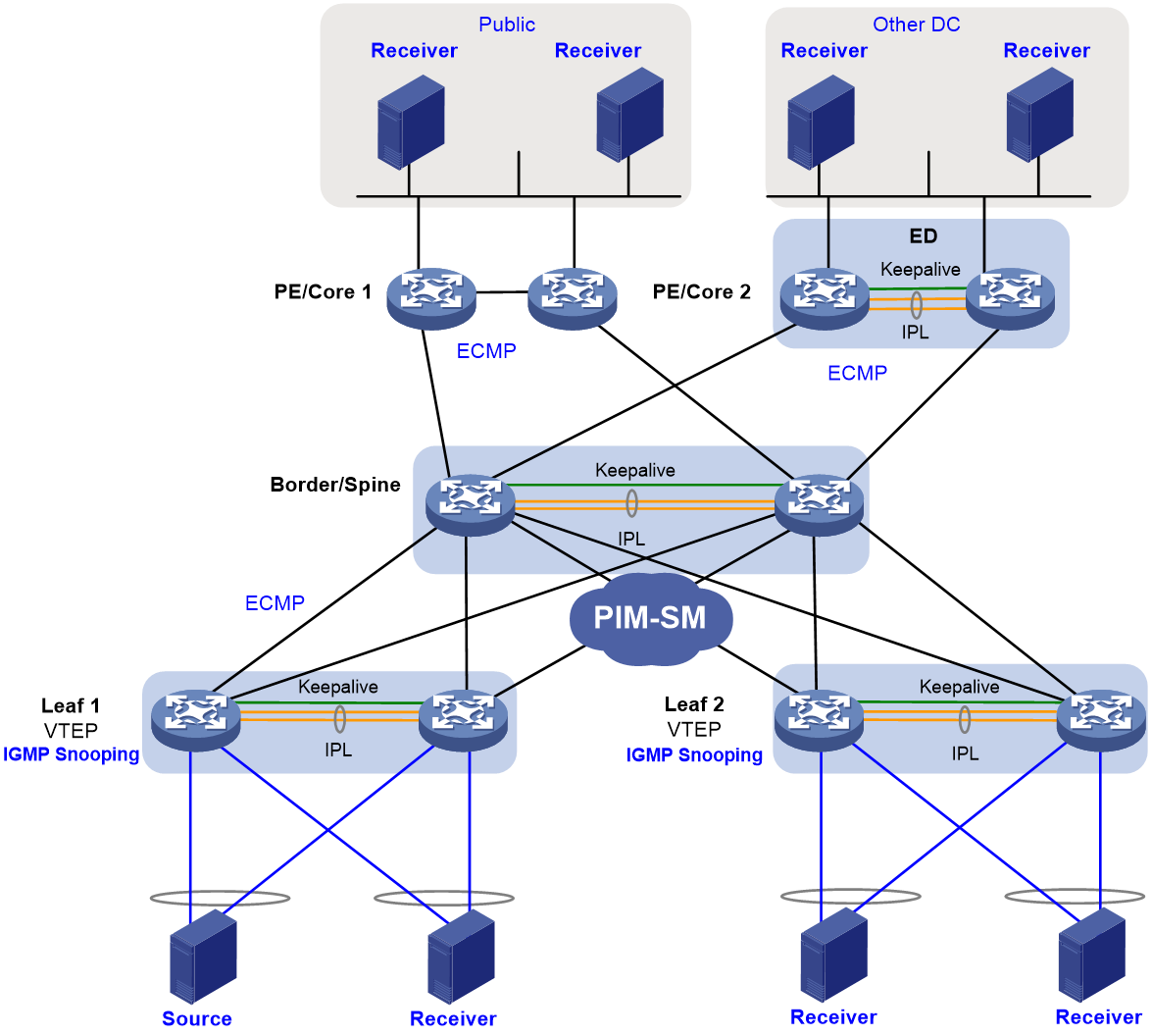
Table 14 Configuration tasks
|
Tasks |
Forwarding |
|
· Configure the leaf devices as VTEPs to provide network access for the multicast source and receivers. · Set up DR systems with the VTEPs, and attach each multicast source or receiver to the local DR system by using two links. · Configure the spine devices as RRs to reflect routes between the leaf and border tiers. · Set up a DR system with the border devices to ensure reliable external network access. · Configure PIM-SM on the interfaces used by the leaf, spine, and border devices to interconnect one another. · Configure IGMP snooping on the leaf devices for multicast forwarding entry creation. · Establish MVXLAN tunnels between the leaf and border tiers. · Configure the EDs to discover multicast receivers outside the local data center based on BGP EVPN routes. |
· When a DR member device receives multicast traffic, it sends the traffic over the IPL for the other DR member device to load share the traffic. ¡ The DR member device with an odd DR system number forwards traffic destined for odd multicast group addresses. ¡ The DR member device with an even DR system number forwards traffic destined for even multicast group addresses. ¡ When one DR member device fails, the other DR member device forwards all multicast traffic. · The MVXLAN tunnel is used to forward multicast traffic between two leaf-tier DR systems or between a leaf-tier DR system and the border-tier DR system. · The device attached to a multicast receiver forwards multicast traffic based on multicast forwarding entries. |
DRNI and DCI
You can use DRNI to virtualize two physical EDs of a data center into a virtual ED to prevent single points of failure from interrupting traffic.
You can use a ring or mesh topology to interconnect the EDs of different data centers. As shown in Figure 20, a ring topology requires fewer physical links than a mesh topology. In a mesh topology, an ED is connected to a remote ED by using multiple physical links, which increases availability of the network. If the link between ED 1 and ED 3 fails in the ring topology, traffic of ED 1 is forwarded to ED 2 and then to ED 4. In a mesh topology, ED 1 can forward traffic directly to ED 4.
The following devices support IPv4 underlay and both IPv4 and IPv6 overlay:
· S6805, S6825, S6850, or S9850 switches that use Release 6616P01.
· S12500X-AF, S6890, S6800, or S6860 switch series.
The following devices support both IPv4 and IPv6 underlay networks:
· S6805, S6825, S6850, and S9850 switches that run F6632 or later.
· S12500G-AF switch series.
The overlay and underlay networks can use different IP versions. For example, you can set up an IPv4 overlay network on top of an IPv6 underlay network.
|
|
NOTE: For more information about support for DRNI on EDs and configuration details, see DRNI and DCI Configuration Example. |

Table 15 Configuration tasks
|
Tasks |
Forwarding |
|
· Establish VXLAN-DCI tunnels between EDs of different data centers, and set up a DR system with the local EDs in each data center. · Establish VXLAN tunnels between the leaf devices and EDs in each data center. · Configure the spine devices as RRs to reflect routes between the leaf devices and EDs. |
· In a DR system, the member EDs use a virtual ED address to set up VXLAN tunnels or VXLAN-DCI tunnels with VTEPs or remote EDs. The member EDs use different BGP peer addresses to establish neighbor relationships with the spine devices or remote EDs. For load sharing and link redundancy, a neighbor sends traffic destined for the virtual ED address to both of the member EDs based on ECMP routes for the underlay network. · A packet is forwarded between VMs in different data centers as follows: a. The source-side leaf device forwards the packet to the local EDs over a VXLAN tunnel. b. An ED decapsulates the packet, encapsulates the packet, and forwards it over a VXLAN-DCI tunnel to a remote data center. c. A remote ED decapsulates the packet, encapsulates the packet, and forwards it over a VXLAN tunnel to the destination-side VTEP. d. The destination-side VTEP decapsulates the packet and forwards it to the destination VM. |
Management network design
As a best practice to prevent forwarding faults from interrupting device management, use management Ethernet interfaces to connect devices to a management network for out-of-band management. Table 16 shows the number of management Ethernet interfaces on the data center devices.
In a DR system, all management Ethernet interfaces on both DR member devices are available. You need to manage the DR member devices separately.
Table 16 Number of management Ethernet interfaces on data center devices
|
Devices providing two or more management Ethernet interfaces |
Devices providing one management Ethernet interface |
|
· S12500X-AF and S12500F series (some MPU models provide four management Ethernet interfaces) · S12500G-AF series · S6890 series · S6805 series · S6825 series · S6850 series · S9850 series · S9820-8C · S9820-64H · S6800-54QF (LS-6800-54QF-H3) · S6800-54QT (LS-6800-54QT-H3) · S6800-54HF · S6800-54HT |
· S6800-32Q · S6800-54QF (LS-6800-54QF) · S6800-54QF (LS-6800-54QF-H1) · S6800-54QT (LS-6800-54QT) · S6800-54QT (LS-6800-54QT-H1) · S6800-2C · S6800-2C-FC · S6800-4C · S6812, S6813 |
Figure 21 shows the management network topology for a data center. The border, spine, and leaf devices are attached to the out-of-band management switch by using management Ethernet interfaces, and the servers are attached to the switch by using BMCs. The switch provides gateway services.
Figure 21 Out-of-band management

High availability for DRNI
High availability of uplinks
You can use the following methods to ensure high availability of uplinks:
· Configure routes—Create one VLAN interface on each DR member device, and set up routing neighbor relationships over the IPL between the VLAN interfaces. When the uplink on a DR member device fails, the device sends its traffic over the IPL for the other DR member device to forward.
¡ If a DR system is attached to standalone upstream devices and ECMP routes are configured for load sharing across the uplinks, you need to interconnect the DR member devices through routing. The Layer 3 connections will be used to transmit traffic between the DR member devices in case of uplink failure.
¡ If a DR system operating at Layer 2 is attached to an upstream DR system, you do not need to interconnect the DR member devices through routing.
· Configure Monitor Link—Associate the DR interfaces with the uplink interfaces. When the uplink interface of a DR member device fails, that device shuts down its DR interface for the other DR member device to forward all traffic. Use this method if the IPL forwards heavy traffic and has bandwidth bottlenecks.
For Monitor Link configuration details, see DRNI+EVPN+Monitor Link Configuration Examples.
High availability of leaf devices
To ensure high availability of leaf devices in a DR system, use the schemes in Table 17.
Figure 22 High availability of leaf devices
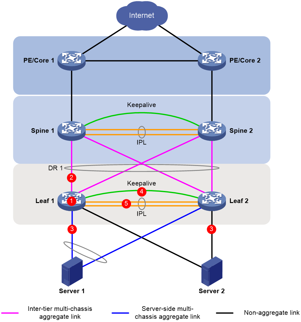
Table 17 Leaf high availability schemes
|
Scenario |
Impact |
High availability scheme |
|
Leaf device failure |
· When Leaf 1 restarts, traffic is switched to Leaf 2. · After Leaf 1 restarts, the following events occur: a. The IPL comes up. b. Leaf 2 sends its MAC address entries and ARP entries over the IPL to Leaf 1. c. Leaf 1 brings up the member ports of the DR interfaces when the data restoration interval set by using the drni restore-delay command expires. d. Leaf 1 brings up all service interfaces after forwarding entries are refreshed for all interfaces. |
N/A |
|
Failure of a link to a spine device |
· When the link between Leaf 1 and Spine 1 fails, all uplink traffic is sent to Spine 2. · Leaf 1 sends traffic over the IPL to Leaf 2 if the link between Leaf 1 and Spine 2 is also down. |
N/A |
|
Link failure on a DR interface |
A server is dualhomed to the leaf devices. When one uplink failures, the server sends all traffic through the other uplink. After the failed uplink recovers, the server sends traffic over both uplinks. |
N/A |
|
Failure of a link to a single-homed server (server NIC in active/standby mode) |
A server is singhomed to both leaf devices by using non-aggregate uplinks, and only one uplink is active. When the active uplink fails, the standby uplink comes up to transmit traffic. If active link preemption is enabled, the original active link preempts the active link role after it recovers. |
N/A |
|
Keepalive link failure |
Keepalive link failure does not affect traffic forwarding. This link is used for multi-active collision detection only when a device or the IPL fails. |
Exclude the interfaces used for keepalive detection from the shutdown action by DRNI MAD. |
|
IPL failure |
· The secondary leaf device places its uplink and downlink interfaces in DRNI MAD DOWN state to switch traffic to the other leaf device. · After the IPL recovers, the interfaces in DRNI MAD DOWN state are brought up after the data restoration interval set by using the drni restore-delay command expires. Then, traffic is switched back to the secondary leaf device. |
Use interfaces from multiple modules or submodules to set up the IPL. |
|
Concurrent IPL and keepalive link failures (DRNI dualhoming) |
If the keepalive link goes down before the IPL goes down, the following events occur: 1. The leaf devices are placed in DRNI standalone mode. 2. Only one leaf device has selected aggregation member ports and forwards traffic. If the IPL goes down before the keepalive link goes down, the following events occur: 1. When the IPL does down, the secondary leaf device places its interfaces in DRNI MAD DOWN state. 2. When the keepalive link goes down, the secondary leaf device brings up its interfaces in DRNI MAD DOWN state. 3. The leaf devices are placed in DRNI standalone mode. Only one leaf device has selected aggregation member ports and forwards traffic. |
· Enable DRNI standalone mode on the leaf devices. · Configure the LACP system ID by using one of the following methods: a. Execute the lacp system-mac and lacp system-priority commands in system view. b. Execute the port lacp system-mac and port lacp system-priority commands in Layer 2 aggregate interface view. |
|
Concurrent IPL and keepalive link failures (server NIC in active/standby mode) |
If the IPL goes down before the keepalive link goes down, the following events occur: 1. When the IPL does down, the secondary leaf device places its interfaces in DRNI MAD DOWN state. 2. When the keepalive link goes down, the secondary leaf device removes its interfaces from DRNI MAD DOWN state. 3. Both leaf devices are primary devices, and forwarding faults occur. To avoid forwarding faults, execute the drni mad persistent command on the secondary device. The secondary device will not remove its interfaces from DRNI MAD DOWN state even if the primary device fails. You must use the drni mad restore command to bring up the interfaces. If the keepalive link goes down before the IPL goes down, recover the links as soon as possible. |
Execute the drni mad persistent command. |
High availability of border devices
To ensure high availability of border devices in a DR system, use the schemes in Table 18.
Figure 23 High availability of border devices

Table 18 Border high availability schemes
|
Scenario |
Impact |
High availability scheme |
|
Border device failure |
· When Border 1 restarts, traffic is switched to Border 2. · After Border 1 restarts, the following events occur: a. The IPL comes up. b. Border 2 sends its MAC address entries and ARP entries over the IPL to Border 1. c. Border 1 brings up the member ports of the DR interfaces when the data restoration interval set by using the drni restore-delay command expires. d. Border 1 brings up all service interfaces after forwarding entries are refreshed for all interfaces. |
N/A |
|
Module failure on a border device |
Uplinks or downlinks might be distributed to multiple modules. When a module fails, traffic is switched to the other modules for forwarding. If no available links exist on the other modules, traffic is switched to the peer DR member device. |
Distribute uplink and downlink to multiple modules or submodules as a best practice. Do not use a single module or submodule to provide uplinks or downlinks. |
|
Uplink failure or upstream device failure |
When the link between a border device and a PE fails, traffic is switched to backup links. After the link recovers, traffic is switched back to it. The switchback speed is determined by the configuration on the PE. |
Configure routing settings as follows on the border devices to reduce the packet loss caused by slow PE-side network convergence. You do not need to execute the following commands if the routing table is small or network convergence is fast on the PEs. For IS-IS, OSPF, or OSPFv3, execute the following commands: · isis peer hold-max-cost duration · ospf peer hold-max-cost duration · ospfv3 peer hold-max-cost duration For BGP, execute the following commands: · bgp apply-policy
on-startup duration second · bgp policy on-startup med |
|
Failure of a link between a border and a firewall or load balancer |
The firewall or load balancer is dualhomed to the border devices. When one link fails, traffic is switched to the other link. When the failed link recovers, traffic is switched back to it. |
N/A |
|
Failure of a link between a border device and a spine device |
ECMP routes exist between the spine devices and the border devices. If a link fails, its traffic is switched to another link. |
|
|
Keepalive link failure |
Keepalive link failure does not affect traffic forwarding. This link is used for multi-active collision detection only when a device or the IPL fails. |
Exclude the interfaces used for keepalive detection from the shutdown action by DRNI MAD. |
|
IPL failure |
· The secondary border device places its uplink and downlink interfaces in DRNI MAD DOWN state to switch traffic to the other border device. · After the IPL recovers, the interfaces in DRNI MAD DOWN state are brought up after the data restoration interval set by using the drni restore-delay command expires. Then, traffic is switched back to the secondary border device. |
Use interfaces from multiple modules or submodules to set up the IPL. |
|
Concurrent IPL and keepalive link failures |
If the keepalive link goes down before the IPL goes down, the following events occur: 1. The border devices are placed in DRNI standalone mode. 2. Only one border device has selected aggregation member ports and forwards traffic. If the IPL goes down before the keepalive link goes down, the following events occur: 1. When the IPL does down, the secondary border device places its interfaces in DRNI MAD DOWN state. 2. When the keepalive link goes down, the secondary border device brings up its interfaces in DRNI MAD DOWN state. 3. The border devices are placed in DRNI standalone mode. Only one border device has selected aggregation member ports and forwards traffic. |
· Enable DRNI standalone mode on the border devices. · Configure the LACP system ID by using one of the following methods: a. Execute the lacp system-mac and lacp system-priority commands in system view. b. Execute the port lacp system-mac and port lacp system-priority commands in Layer 2 aggregate interface view. |
Recommended hardware and software versions
You must install the latest patches (if any) for the recommended software versions on all devices.
If the hardware and software versions listed in the following matrix conflict with those used in configuration examples, use the hardware and software versions in the configuration examples. If you have any doubts, contact H3C Support.
Table 19 Recommended hardware and software versions
|
Device role |
Scenario |
Hardware |
Software version |
|
Border/ED |
Medium and large networks |
H-series modules for the S12500X-AF switches |
R2820 |
|
All modules supported by the S12500G-AF switches |
R7624P12 and later |
||
|
Small networks |
Same as the leaf devices |
Same as the leaf devices |
|
|
Spine |
N/A |
H-series modules for the S12500X-AF switches |
R2820 |
|
All modules supported by the S12500G-AF switches |
R7624P12 and later |
||
|
Leaf |
10GE connection |
· S6800 · S6860 · S6805 · S6890 · S6850-2C or S9850-4C with 10GE interface expansion modules installed · S6812, S6813 |
· S6800, S6860: F2707 · S6805, S6850, S9850: R6635 · S6890: R2820 · S6812, S6813: Use a software version where DRNI has been renamed M-LAG as a best practice. This network planning guide does not apply to these switches. |
|
25GE connection |
· S6825 · S6850-56HF · S6850-2C or S9820-4C with 25GE interface expansion modules installed |
S6825, S6850, S9850: R6635 |
|
|
40GE connection |
· S6800 · S6850-2C or S9850-4C with 40GE interface expansion modules installed |
· S6800: F2707 · S6850, S9850: R6635 |
|
|
100GE connection |
· S9850-32H · S6850-2C or S9850-4C with 100GE interface expansion modules installed · S9820-8C · S9820-64H |
S6850, S9850, S9820-8C, S9820-64H: R6635 |