- Table of Contents
-
- H3C Data Center Switches DRNI Configuration Guide-6W103
- 00-DRNI network planning
- 01-DRNI+IPv4 and IPv6 Dual-Active VLAN Gateway Configuration Example
- 02-Multi-Layer DRNI+STP+Dual-Active VLAN Gateway Configuration Examples
- 03-Multi-Layer DRNI+Dual-Active VLAN Gateway+OSPF Configuration Examples
- 04-Multi-tier DRNI+Spine Gateways+ECMP Paths to External Network Configuration Example
- 05-DRNI and VRRP Configuration Example
- 06-DRNI+RDMA Configuration Example
- 07-DRNI and EVPN Distributed Gateway (IS-IS for underlay routing) Configuration Example
- 08-DRNI and EVPN Distributed Gateway (BGP for Underlay Routing) Configuration Example
- 09-DRNI+EVPN Distributed Gateway (OSPF on Underlay Network)+DHCP Relay+Microsegmentation+Service Chain Configuration Example
- 10-DRNI+EVPN Centralized Gateway Configuration Example
- 11-Access to DRNI Through Dynamic Routing and Distributed EVPN Gateways Configuration Example
- 12-DRNI+EVPN+Monitor Link Configuration Examples
- 13-DRNI and MVXLAN Configuration Example
- 14-DRNI and DCI Configuration Example
- 15-DRNI+EVPN DC Switchover Upon Border Failure Configuration Examples
- Related Documents
-
| Title | Size | Download |
|---|---|---|
| 04-Multi-tier DRNI+Spine Gateways+ECMP Paths to External Network Configuration Example | 287.15 KB |
Example: Configuring multi-tier DRNI+spine gateways+ECMP paths to the external network
Configuring the links towards the servers
Configuring the interfaces facing single-homed downstream devices
Configuring the links towards the spine tier
Configuring the links towards the leaf tier
Configuring the dual-active VLAN gateways
Configuring the interfaces connected to the external network
Testing network convergence upon single points of failure
Verifying the traffic interruption time
Verifying the expansion result
Replacing a switching fabric module
Example: Configuring multi-tier DRNI+spine gateways+ECMP paths to the external network
Network configuration
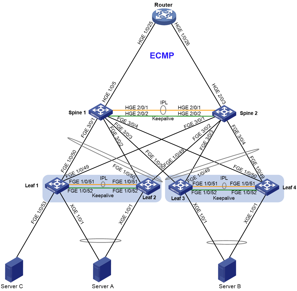
As shown in Figure 1, configure the network as follows:
· Set up a DR system at the spine tier to offer gateway services.
· Set up two DR systems at the leaf tier to offer access services to the servers.
· Attach each server to a leaf DR system by using two links or a single link.
· Attach each leaf device to the spine devices by using DR interfaces.
· Configure the router to provide access to the external network.
|
Device |
Interface |
IP address |
Interface description and peer device and interface |
|
Spine 1 |
HGE2/0/1 |
N/A |
IPP Spine 2: HGE2/0/1 |
|
HGE2/0/2 |
2.0.0.1/30 |
Keepalive interface Spine 2: HGE2/0/2 |
|
|
HGE1/0/5 |
25.1.1.1/24 |
Router: HGE1/0/25 |
|
|
FGE3/0/1 |
N/A |
Leaf 1: FGE1/0/50 |
|
|
FGE3/0/2 |
N/A |
Leaf 2: FGE1/0/50 |
|
|
FGE3/0/3 |
N/A |
Leaf 3: FGE1/0/50 |
|
|
FGE3/0/4 |
N/A |
Leaf 4: FGE1/0/50 |
|
|
Vlan-interface21 |
21.1.1.1/24 |
Leaf 1 and Leaf 2 Service VLAN |
|
|
Vlan-interface31 |
31.1.1.1/24 |
Leaf 3 and Leaf 4 Service VLAN |
|
|
Vlan-interface2000 |
192.168.2.1/30 |
East-west failover VLAN |
|
|
Spine 2 |
HGE2/0/1 |
N/A |
IPP Spine 1: HGE2/0/1 |
|
HGE2/0/2 |
2.0.0.2/30 |
Keepalive interface Spine 1: HGE2/0/2 |
|
|
HGE2/0/3 |
23.1.1.1/24 |
Router: HGE1/0/26 |
|
|
FGE3/0/1 |
N/A |
Leaf 1: FGE1/0/49 |
|
|
FGE3/0/2 |
N/A |
Leaf 2: FGE1/0/49 |
|
|
FGE3/0/3 |
N/A |
Leaf 3: FGE1/0/49 |
|
|
FGE3/0/4 |
N/A |
Leaf 4: FGE1/0/49 |
|
|
Vlan-interface21 |
21.1.1.1/24 |
Leaf 1 and Leaf 2 Service VLAN |
|
|
Vlan-interface31 |
31.1.1.1/24 |
Leaf 3 and Leaf 4 Service VLAN |
|
|
Vlan-interface2000 |
192.168.2.2/30 |
East-west failover VLAN |
|
|
Leaf 1 |
XGE1/0/1 |
N/A |
Member port of a DR interface Server A |
|
FGE1/0/49 |
N/A |
Spine 2: FGE3/0/1 |
|
|
FGE1/0/50 |
N/A |
Spine 1: FGE3/0/1 |
|
|
FGE1/0/51 |
N/A |
IPP Leaf 2: FGE1/0/51 |
|
|
FGE1/0/52 |
1.0.0.1/30 |
Keepalive interface Leaf 2: FGE1/0/52 |
|
|
FGE1/0/53 |
N/A |
Single-homed link Server C |
|
|
Leaf 2 |
XGE1/0/1 |
N/A |
Member port of a DR interface Server A |
|
FGE1/0/49 |
N/A |
Spine 2: FGE3/0/2 |
|
|
FGE1/0/50 |
N/A |
Spine 1: FGE3/0/2 |
|
|
FGE1/0/51 |
N/A |
IPP Leaf 1: FGE1/0/51 |
|
|
FGE1/0/52 |
1.0.0.2/30 |
Keepalive interface Leaf 1: FGE1/0/52 |
|
|
Leaf 3 |
XGE1/0/1 |
N/A |
Member port of a DR interface Server B |
|
FGE1/0/49 |
N/A |
Spine 2: FGE3/0/3 |
|
|
FGE1/0/50 |
N/A |
Spine 1: FGE3/0/3 |
|
|
FGE1/0/51 |
N/A |
IPP Leaf 4: FGE1/0/51 |
|
|
FGE1/0/52 |
1.0.0.5/30 |
Keepalive interface Leaf 4: FGE1/0/52 |
|
|
Leaf 4 |
XGE1/0/1 |
N/A |
Member port of a DR interface Server B |
|
FGE1/0/49 |
N/A |
Spine 2: FGE3/0/4 |
|
|
FGE1/0/50 |
N/A |
Spine 1: FGE3/0/4 |
|
|
FGE1/0/51 |
N/A |
IPP Leaf 3: FGE1/0/51 |
|
|
FGE1/0/52 |
1.0.0.6/30 |
Keepalive interface Leaf 3: FGE1/0/52 |
|
|
Router |
HGE1/0/25 |
25.1.1.2 |
Spine 1: HGE2/0/3 |
|
HGE1/0/26 |
23.1.1.2 |
Spine 2: HGE2/0/3 |
Applicable product matrix
|
|
IMPORTANT: In addition to running an applicable software version, you must also install the most recent patch, if any. |
|
Role |
Device |
Software version |
|
Spine |
S12500X-AF |
R2820 |
|
S12500G-AF |
R7624P12 |
|
|
Border or leaf |
S6800, S6860 |
F2715 and higher F27xx or R27xx versions Do not use F28xx or R28xx versions. |
|
S6805, S6825, S6850, S9850, S9820-64H, S9820-8C |
R6635 |
|
|
S6890 |
R2820 |
|
|
S6812, S6813 |
Under development. To obtain the latest images, contact Technical Support. |
Restrictions and guidelines
· The member devices in a DR system must use the same DR system MAC address. Different DR systems must each have a unique DR system MAC address on the network.
· As a best practice, run a dynamic routing protocol between the spine devices and the external network. If you use static routing, traffic interruption might occur upon the reboot of a spine device. This issue typically occurs if the service module accommodating an IPP, keepalive interface, or DR interface requires longer time to reboot than other service modules. To resolve the traffic interruption issue, use one of the following methods:
¡ Select an interface operating at the same speed from each service module and assign the interfaces to the aggregation group of the IPP. This method ensures that the IPP recovers prior to other interfaces. If you select interfaces operating at different speeds, execute the link-aggregation ignore speed command on the IPP. This method might result in traffic congestion or uneven traffic distribution on aggregate links as the number of selected ports might be insufficient.
¡ Create a monitor link group on the spine devices. Configure the router-facing interfaces as uplink interfaces for the monitor link group, and the member interfaces of leaf-facing DR interfaces as downlink interfaces. This method ensures that the uplink interfaces come up prior to the downlink DR interfaces. If you use this method, you must manually change the downlink interfaces in the monitor link group in response to deletion or addition of DR groups and membership changes of DR groups.
Configuring the leaf nodes
Procedure summary
· Configuring the links towards the servers
· Configuring the interfaces facing single-homed downstream devices
· Configuring the links towards the spine tier
|
|
NOTE: The configuration of Leaf 3 and Leaf 4 is similar to that of Leaf 1 and Leaf 2. This configuration example provides only configuration tasks for Leaf 1 and Leaf 2. |
Configuring DRNI
|
Leaf 1 (S6800) |
Leaf 2 (S6800) |
Configuration method |
Description |
Remarks |
|
interface FortyGigE1/0/52 |
interface FortyGigE1/0/52 |
Manual |
Enter the interface view for the keepalive link. |
N/A |
|
port link-mode route |
port link-mode route |
Manual |
Configure the interface for keepalive detection to operate in route mode as a Layer 3 interface. |
N/A |
|
ip address 1.0.0.1 255.255.255.252 |
ip address 1.0.0.2 255.255.255.252 |
Manual |
Assign an IP address to the keepalive interface. |
N/A |
|
quit |
quit |
Manual |
Return to system view. |
N/A |
|
drni system-mac 00e0-fc00-5800 |
drni system-mac 00e0-fc00-5800 |
Manual |
Set the MAC address of the DR system. |
You must assign the same DR system MAC address to the member devices in a DR system. |
|
drni system-number 1 |
drni system-number 2 |
Manual |
Set the DR system number. |
You must assign different DR system numbers to the member devices in a DR system. |
|
drni system-priority 100 |
drni system-priority 100 |
Manual |
(Optional.) Set the DR system priority. |
You must set the same DR system priority on the member devices in a DR system. The default DR system priority is 32768. The smaller the value, the higher the priority. |
|
drni standalone enable |
drni standalone enable |
Manual |
Enable DRNI standalone mode. |
N/A |
|
drni keepalive ip destination 1.0.0.2 source 1.0.0.1 |
drni keepalive ip destination 1.0.0.1 source 1.0.0.2 |
Manual |
Configure the destination and source IP addresses of keepalive packets. |
Exclude the interfaces providing the source and destination IP addresses from the shutdown action by DRNI MAD. |
|
drni mad exclude interface FortyGigE1/0/52 |
drni mad exclude interface FortyGigE1/0/52 |
Manual |
Exclude the keepalive interface from the shutdown action by DRNI MAD. |
N/A |
|
drni restore-delay 300 |
drni restore-delay 300 |
Manual |
Set the data restoration interval. |
This parameter ensures that forwarding entry synchronization finishes before interfaces are brought up. |
|
interface Bridge-Aggregation1 |
interface Bridge-Aggregation1 |
Manual |
Create a Layer 2 aggregate interface and enter its view. |
N/A |
|
port link-type trunk |
port link-type trunk |
Manual |
Set the link type of the interface to trunk. |
N/A |
|
port trunk permit vlan all |
port trunk permit vlan all |
Manual |
Configure the trunk interface to permit all VLANs. |
N/A |
|
interface FortyGigE1/0/51 |
interface FortyGigE1/0/51 |
Manual |
Enter interface view. |
N/A |
|
port link-type trunk |
port link-type trunk |
Manual |
Set the link type of the interface to trunk. |
N/A |
|
port trunk permit vlan all |
port trunk permit vlan all |
Manual |
Configure the trunk interface to permit all VLANs. |
N/A |
|
port link-aggregation group 1 |
port link-aggregation group 1 |
Manual |
Assign the interface to aggregation group 1. |
N/A |
|
interface Bridge-Aggregation1 |
interface Bridge-Aggregation1 |
Manual |
Enter Layer 2 aggregate interface view. |
N/A |
|
link-aggregation mode dynamic |
link-aggregation mode dynamic |
Manual |
Configure the aggregate interface to operate in dynamic mode. |
N/A |
|
port drni intra-portal-port 1 |
port drni intra-portal-port 1 |
Manual |
Specify the aggregate interface as an IPP. |
N/A |
|
undo mac-address static source-check enable |
undo mac-address static source-check enable |
Manual |
Disable static source check. |
Disable static source check on the IPP and spine-facing uplink interfaces. |
Configuring the links towards the servers
|
Leaf 1 (S6800) |
Leaf 2 (S6800) |
Configuration method |
Description |
Remarks |
|
VLAN 21 |
VLAN 21 |
Manual |
Create VLAN 21. |
N/A |
|
quit |
quit |
Manual |
Return to the previous view. |
N/A |
|
interface Bridge-Aggregation101 |
interface Bridge-Aggregation101 |
Manual |
Create an aggregate interface and enter its view. This interface will be assigned to a server-facing DR group. |
N/A |
|
port link-type trunk |
port link-type trunk |
Manual |
Set the link type of the interface to trunk. |
N/A |
|
port trunk permit vlan 21 |
port trunk permit vlan 21 |
Manual |
Assign the trunk interface to VLAN 21. |
N/A |
|
link-aggregation mode dynamic |
link-aggregation mode dynamic |
Manual |
Configure the aggregate interface to operate in dynamic mode. |
N/A |
|
port drni group 1 |
port drni group 1 |
Manual |
Assign the aggregate interface to DR group 1. |
N/A |
|
port lacp system-priority 101 |
port lacp system-priority 100 |
Manual |
Set the LACP priority. |
Set different LACP priorities for different DR member devices, so that only member ports with a higher priority are selected upon brain split. |
|
quit |
quit |
Manual |
Return to the previous view. |
N/A |
|
interface Ten-GigabitEthernet1/0/1 |
interface Ten-GigabitEthernet 1/0/1 |
Manual |
Enter the view of a DR aggregation member port. |
N/A |
|
port link-type trunk |
port link-type trunk |
Manual |
Set the link type of the interface to trunk. |
N/A |
|
port trunk permit vlan 21 |
port trunk permit vlan 21 |
Manual |
Assign the trunk interface to VLAN 21. |
N/A |
|
port link-aggregation group 101 |
port link-aggregation group 101 |
Manual |
Assign the interface to aggregation group 101. |
N/A |
|
quit |
quit |
Manual |
Return to the previous view. |
N/A |
Configuring the interfaces facing single-homed downstream devices
|
Leaf 1 (S6800) |
Leaf 2 (S6800) |
Configuration method |
Description |
|
interface FortyGigE1/0/53 |
interface FortyGigE1/0/53 |
Manual |
Enter the view of a DR aggregation member port. |
|
port link-type trunk |
port link-type trunk |
Manual |
Set the link type of the interface to trunk. |
|
port trunk permit vlan 21 |
port trunk permit vlan 21 |
Manual |
Assign the trunk interface to VLAN 21. |
|
|
IMPORTANT: To prevent an IPL down event from triggering the DRNI MAD DOWN action on the secondary DR device, attach a single-homed downstream device to the primary DR device. |
Configuring the links towards the spine tier
|
Leaf 1 (S6800) |
Leaf 2 (S6800) |
Configuration method |
Description |
Remarks |
|
interface Bridge-Aggregation102 |
interface Bridge-Aggregation102 |
Manual |
Create an aggregate interface to be assigned to a DR group and enter aggregate interface view. |
N/A |
|
port link-type trunk |
port link-type trunk |
Manual |
Set the link type of the interface to trunk. |
N/A |
|
port trunk permit vlan 21 |
port trunk permit vlan 21 |
Manual |
Assign the trunk interface to VLAN 21. |
N/A |
|
link-aggregation mode dynamic |
link-aggregation mode dynamic |
Manual |
Configure the aggregate interface to operate in dynamic mode. |
N/A |
|
port drni group 2 |
port drni group 2 |
Manual |
Assign the aggregate interface to DR group 2. |
N/A |
|
port lacp system-priority 101 |
port lacp system-priority 100 |
Manual |
Set the LACP priority. |
Set different LACP priorities for different DR member devices, so that only member ports with a higher priority are selected upon brain split. |
|
quit |
quit |
Manual |
Return to the previous view. |
N/A |
|
interface FortyGigE1/0/49 |
interface FortyGigE1/0/49 |
Manual |
Enter the view of a DR aggregation member port. |
N/A |
|
port link-type trunk |
port link-type trunk |
Manual |
Set the link type of the interface to trunk. |
N/A |
|
port trunk permit vlan 21 |
port trunk permit vlan 21 |
Manual |
Assign the trunk interface to VLAN 21. |
N/A |
|
port link-aggregation group 102 |
port link-aggregation group 102 |
Manual |
Assign the interface to aggregation group 102. |
N/A |
|
interface FortyGigE1/0/50 |
interface FortyGigE1/0/50 |
Manual |
Enter the view of a DR aggregation member port. |
N/A |
|
port link-type trunk |
port link-type trunk |
Manual |
Set the link type of the interface to trunk. |
N/A |
|
port trunk permit vlan 21 |
port trunk permit vlan 21 |
Manual |
Assign the trunk interface to VLAN 21. |
N/A |
|
port link-aggregation group 102 |
port link-aggregation group 102 |
Manual |
Assign the interface to aggregation group 102. |
N/A |
|
quit |
quit |
Manual |
Return to the previous view. |
N/A |
Configuring the spine nodes
Procedure summary
· Configuring the links towards the leaf tier
· Configuring the dual-active VLAN gateways
· Configuring the interfaces connected to the external network
Configuring DRNI
|
Spine 1 |
Spine 2 |
Configuration method |
Description |
Remarks |
|
interface HundredGigE2/0/2 |
interface HundredGigE2/0/2 |
Manual |
Enter the interface view for the keepalive link. |
N/A |
|
port link-mode route |
port link-mode route |
Manual |
Configure the interface for keepalive detection to operate in route mode as a Layer 3 interface. |
N/A |
|
ip address 2.0.0.1 255.255.255.252 |
ip address 2.0.0.2 255.255.255.252 |
Manual |
Assign an IP address to the interface. |
N/A |
|
quit |
quit |
Manual |
Return to system view. |
N/A |
|
drni restore-delay 300 |
drni restore-delay 300 |
Manual |
Set the data restoration interval. |
Set this parameter to 200 on a fixed-port device. |
|
drni role priority 100 |
drni role priority 101 |
Manual |
Set DR role priority. |
The DR member devices negotiate their DR roles based on the DR role priority. The smaller the value, the higher the priority to be the primary DR devices. |
|
drni system-mac 542b-de0c-0300 |
drni system-mac 542b-de0c-0300 |
Manual |
Set the MAC address of the DR system. |
You must assign the same DR system MAC address to the member devices in a DR system. |
|
drni system-number 1 |
drni system-number 2 |
Manual |
Set the DR system number. |
You must assign different DR system numbers to the member devices in a DR system. |
|
drni system-priority 100 |
drni system-priority 100 |
Manual |
(Optional.) Set the DR system priority. |
You must set the same DR system priority on the member devices in a DR system. The default DR system priority is 32768. The smaller the value, the higher the priority. |
|
drni standalone enable |
drni standalone enable |
Manual |
Enable DRNI standalone mode. |
N/A |
|
drni keepalive ip destination 2.0.0.2 source 2.0.0.1 |
drni keepalive ip destination 2.0.0.1 source 2.0.0.2 |
Manual |
Configure the destination and source IP addresses of keepalive packets. |
Specify a VPN instance according to the network environment. For the interfaces that will be shut down by DRNI MAD, exclude them from the DRNI MAD DOWN action as needed. |
|
drni mad exclude interface HundredGigE2/0/2 |
drni mad exclude interface HundredGigE2/0/2 |
Manual |
Exclude the keepalive interface from the shutdown action by DRNI MAD. |
N/A |
|
interface Bridge-Aggregation 1 |
interface Bridge-Aggregation 1 |
Manual |
Create Bridge-Aggregation 1. |
N/A |
|
quit |
quit |
Manual |
Return to system view. |
N/A |
|
interface HundredGigE2/0/1 |
interface HundredGigE2/0/1 |
Manual |
Enter the view of a member port of the IPP. |
N/A |
|
port link-aggregation group 1 |
port link-aggregation group 1 |
Manual |
Assign the interface to aggregation group 1. |
N/A |
|
quit |
quit |
Manual |
Return to the previous view. |
N/A |
|
interface Bridge-Aggregation 1 |
interface Bridge-Aggregation 1 |
Manual |
Enter the view of Bridge-Aggregation 1. |
N/A |
|
link-aggregation mode dynamic |
link-aggregation mode dynamic |
Manual |
Configure the aggregate interface to operate in dynamic mode. |
N/A |
|
port drni intra-portal-port 1 |
port drni intra-portal-port 1 |
Manual |
Specify the aggregate interface as an IPP. |
N/A |
|
port link-type trunk |
port link-type trunk |
Manual |
Set the link type of the interface to trunk. |
N/A |
|
port trunk permit vlan all |
port trunk permit vlan all |
Manual |
Configure the trunk interface to permit all VLANs. |
N/A |
|
port trunk pvid vlan 4094 |
port trunk pvid vlan 4094 |
Manual |
Set the PVID to 4094 for the trunk interface. |
N/A |
Configuring the links towards the leaf tier
|
Spine 1 |
Spine 2 |
Configuration method |
Description |
Remarks |
|
Vlan 21 31 |
Vlan 21 31 |
Manual |
Create VLANs. |
N/A |
|
quit |
quit |
Manual |
Return to system view. |
N/A |
|
interface Bridge-Aggregation102 |
interface Bridge-Aggregation102 |
Manual |
Enter the view of the DR group member aggregate interface connected to Leaf 1 and Leaf 2. |
N/A |
|
port link-type trunk |
port link-type trunk |
Manual |
Set the link type of the interface to trunk. |
N/A |
|
port trunk permit vlan 21 |
port trunk permit vlan 21 |
Manual |
Assign the trunk interface to VLAN 21. |
N/A |
|
link-aggregation mode dynamic |
link-aggregation mode dynamic |
Manual |
Configure the aggregate interface to operate in dynamic mode. |
N/A |
|
port lacp system-priority 101 |
port lacp system-priority 100 |
Manual |
Set the LACP priority. |
Set different LACP priorities for different DR member devices, so that only member ports with a higher priority are selected upon brain split. |
|
port drni group 2 |
port drni group 2 |
Manual |
Assign the aggregate interface to DR group 2. |
N/A |
|
interface FortyGigE 3/0/1 |
interface FortyGigE 3/0/1 |
Manual |
Enter the view of a DR aggregation member port. |
N/A |
|
port link-type trunk |
port link-type trunk |
Manual |
Set the link type of the interface to trunk. |
N/A |
|
port trunk permit vlan 21 |
port trunk permit vlan 21 |
Manual |
Assign the trunk interface to VLAN 21. |
N/A |
|
port link-aggregation group 102 |
port link-aggregation group 102 |
Manual |
Assign the interface to aggregation group 1.02 |
N/A |
|
interface FortyGigE 3/0/2 |
interface FortyGigE 3/0/2 |
Manual |
Enter the view of a DR aggregation member port. |
N/A |
|
port link-type trunk |
port link-type trunk |
Manual |
Set the link type of the interface to trunk. |
N/A |
|
port trunk permit vlan 21 |
port trunk permit vlan 21 |
Manual |
Assign the trunk interface to VLAN 21. |
N/A |
|
port link-aggregation group 102 |
port link-aggregation group 102 |
Manual |
Assign the interface to aggregation group 1.02 |
N/A |
|
quit |
quit |
Manual |
Return to system view. |
N/A |
|
interface Bridge-Aggregation103 |
interface Bridge-Aggregation103 |
Manual |
Enter the view of the DR group member aggregate interface connected to Leaf 3 and Leaf 4. |
N/A |
|
port link-type trunk |
port link-type trunk |
Manual |
Set the link type of the interface to trunk. |
N/A |
|
port trunk permit vlan 31 |
port trunk permit vlan 31 |
Manual |
Assign the trunk interface to VLAN 31. |
N/A |
|
link-aggregation mode dynamic |
link-aggregation mode dynamic |
Manual |
Configure the aggregate interface to operate in dynamic mode. |
N/A |
|
port lacp system-priority 101 |
port lacp system-priority 100 |
Manual |
Set the LACP priority. |
Set different LACP priorities for different DR member devices, so that only member ports with a higher priority are selected upon brain split. |
|
port drni group 3 |
port drni group 3 |
Manual |
Assign the aggregate interface to DR group 2. |
N/A |
|
interface FortyGigE 3/0/3 |
interface FortyGigE 3/0/3 |
Manual |
Enter the view of a DR aggregation member port. |
N/A |
|
port link-type trunk |
port link-type trunk |
Manual |
Set the link type of the interface to trunk. |
N/A |
|
port trunk permit vlan 31 |
port trunk permit vlan 31 |
Manual |
Assign the trunk interface to VLAN 31. |
N/A |
|
port link-aggregation group 103 |
port link-aggregation group 103 |
Manual |
Assign the interface to aggregation group 1.03 |
N/A |
|
interface FortyGigE3/0/4 |
interface FortyGigE3/0/4 |
Manual |
Enter the view of a DR aggregation member port. |
N/A |
|
port link-type trunk |
port link-type trunk |
Manual |
Set the link type of the interface to trunk. |
N/A |
|
port trunk permit vlan 31 |
port trunk permit vlan 31 |
Manual |
Assign the trunk interface to VLAN 31. |
N/A |
|
port link-aggregation group 103 |
port link-aggregation group 103 |
Manual |
Assign the interface to aggregation group 1.03 |
N/A |
|
quit |
quit |
Manual |
Return to the previous view. |
N/A |
Configuring the dual-active VLAN gateways
|
Spine 1 |
Spine 2 |
Configuration method |
Description |
Remarks |
|
routing-interface base-mac 3c8c-4003-8ba5 |
routing-interface base-mac 3c8c-4003-8b41 |
Manual |
Configure the base MAC address. |
The base MAC address of Spine 2 is equal to that of Spine 1 + 0X64. This step only applies to S12500X-AF and S6890 switches. |
|
interface Vlan-interface21 |
interface Vlan-interface21 |
Manual |
Create the VLAN interface of VLAN 21, the service VLAN on Leaf 1 and Leaf 2. |
N/A |
|
ip address 21.1.1.1 255.255.255.0 |
ip address 21.1.1.1 255.255.255.0 |
Manual |
Assign an IP address to the interface. |
N/A |
|
mac-address 3c8c-4003-8c08 |
mac-address 3c8c-4003-8c08 |
Manual |
Assign a MAC address to the interface. |
N/A |
|
quit |
quit |
Manual |
Return to the previous view. |
N/A |
|
drni mad exclude interface Vlan-interface21 |
drni mad exclude interface Vlan-interface21 |
Manual |
Exclude the VLAN interface from the DRNI MAD DOWN action. |
N/A |
|
interface Vlan-interface31 |
interface Vlan-interface31 |
Manual |
Create the VLAN interface of VLAN 31, the service VLAN on Leaf 3 and Leaf 4. |
N/A |
|
ip address 31.1.1.1 255.255.255.0 |
ip address 31.1.1.1 255.255.255.0 |
Manual |
Assign an IP address to the interface. |
N/A |
|
mac-address 3c8c-4003-8c09 |
mac-address 3c8c-4003-8c09 |
Manual |
Assign a MAC address to the interface. |
N/A |
|
quit |
quit |
Manual |
Return to system view. |
N/A |
|
drni mad exclude interface Vlan-interface31 |
drni mad exclude interface Vlan-interface31 |
Manual |
Exclude the VLAN interface from the DRNI MAD DOWN action. |
N/A |
|
|
IMPORTANT: · On the S12500X-AF and S6890 switches, make sure the base MAC address plus the number of reserved MAC addresses produces a MAC address that has the same higher 36 bits as the base MAC address. · You cannot edit or delete the base MAC address within 30 seconds after you configure it. · When you assign a MAC address to a Layer 3 interface after the base MAC address configuration, make sure the following requirements are met: ¡ The MAC address must have the same higher 36 bits as the base MAC address. ¡ The MAC address must be no lower than the base MAC address plus the number of reserved MAC addresses |
Configuring the interfaces connected to the external network
|
Spine 1 |
Spine 2 |
Configuration method |
Description |
|
ospf 1 router-id 2.1.1.1 |
ospf 1 router-id 2.1.1.2 |
Manual |
Start an OSPF process. |
|
import-route direct |
import-route direct |
Manual |
Redistribute direct routes. |
|
area 0.0.0.0 |
area 0.0.0.0 |
Manual |
Create an OSPF area. |
|
interface HundredGigE1/0/5 |
interface HundredGigE2/0/3 |
Manual |
Enter the view of the router-facing interface. |
|
port link-mode route |
port link-mode route |
Manual |
Configure the interface for keepalive detection to operate in route mode as a Layer 3 interface. |
|
ip address 25.1.1.1 255.255.255.0 |
ip address 23.1.1.1 255.255.255.0 |
Manual |
Assign an IP address to the interface. |
|
ospf 1 area 0.0.0.0 |
ospf 1 area 0.0.0.0 |
Manual |
Enable OSPF on the interface. |
|
quit |
quit |
Manual |
Return to system view. |
|
Vlan 2000 |
Vlan 2000 |
Manual |
Create the east-west failover VLAN. |
|
quit |
quit |
Manual |
Return to system view. |
|
interface Vlan-interface2000 |
interface Vlan-interface2000 |
Manual |
Create the VLAN interface of the east-west failover VLAN. |
|
ip address 192.168.2.1 255.255.255.252 |
ip address 192.168.2.2 255.255.255.252 |
Manual |
Assign an IP address to the interface. |
|
ospf 1 area 0.0.0.0 |
ospf 1 area 0.0.0.0 |
Manual |
Enable OSPF on the VLAN interface. |
Configuring the router
|
Router |
Configuration method |
Description |
|
ospf 1 router-id 3.1.1.1 |
Manual |
Start an OSPF process. |
|
area 0.0.0.0 |
Manual |
Create an OSPF area. |
|
interface HundredGigE1/0/25 |
Manual |
Enter the view of the interface connected to Spine 1. |
|
port link-mode route |
Manual |
Configure the interface for keepalive detection to operate in route mode as a Layer 3 interface. |
|
ip address 25.1.1.2 24 |
Manual |
Assign an IP address to the interface connected to Spine 1. |
|
ospf 1 area 0.0.0.0 |
Manual |
Enable OSPF on the interface. |
|
quit |
Manual |
N/A |
|
interface HundredGigE1/0/26 |
Manual |
Enter the view of the interface connected to Spine 2. |
|
port link-mode route |
Manual |
Configure the interface for keepalive detection to operate in route mode as a Layer 3 interface. |
|
ip address 23.1.1.2 24 |
Manual |
Assign an IP address to the interface connected to Spine 2. |
|
ospf 1 area 0.0.0.0 |
Manual |
Enable OSPF on the interface. |
Traffic forwarding models
The forwarding model matrix provides the following characteristics of traffic:
· No.—Traffic number in the U-X-XXX format:
¡ U—Underlay traffic.
¡ X—Protocol number, which can be 4 (IPv4).
¡ XXX—Traffic sequence number, starting from 201.
· Traffic type—Type of underlay traffic, which can be IPv4 known unicast.
· Direction—Direction of underlay traffic, which can be south-north or east-west across leaf DR systems.
· Forwarding path—Nodes that underlay traffic traverses.
· Traffic simulation—Traffic simulation method. Typically, a tester is used to simulate server traffic.
· Load—Traffic size, which can be light (less than 1000 flows) and heavy (more than 1000 flows).
Table 1 Traffic forwarding models
|
No. |
Traffic type |
Direction |
Forwarding path |
Traffic simulation |
Load |
Remarks |
|
U-4-201 |
IPv4 known unicast |
East-west across leaf DR systems |
Server A > Leaf 1 & Leaf 2 > Spine 1 & Spine 2 > Leaf 3 & Leaf 4 > Server B |
Bond4+ tester |
Light |
Layer 3 forwarding between PMs. |
|
U-4-202 |
IPv4 known unicast |
East-west across leaf DR systems |
Server B > Leaf 1 & Leaf 2 > Spine 1 & Spine 2 > Leaf 1 & Leaf 2 > Server A |
Bond4+ tester |
Light |
Layer 3 forwarding between PMs. |
|
U-4-203 |
IPv4 known unicast |
South-north |
Server A > Leaf 1 & Leaf 2 > Spine 1 & Spine 2 > Router |
Bond4+ tester |
Light |
Layer 3 forwarding between PMs and the external network. |
|
U-4-204 |
IPv4 known unicast |
South-north |
Router > Spine 1 & Spine 2 > Leaf 1 & Leaf 2 > Server A |
Bond4+ tester |
Light |
Layer 3 forwarding between PMs and the external network. |
|
U-4-205 |
IPv4 known unicast |
East-west across leaf DR systems |
Server C > Leaf 1 > Spine 1 & Spine 2 > Leaf 3 & Leaf 4 > Server B |
Bond4+ tester |
Light |
Layer 3 forwarding between PMs. |
|
U-4-206 |
IPv4 known unicast |
East-west across leaf DR systems |
Server B > Leaf 3 & Leaf 4 > Spine 1 & Spine 2 > Leaf 1 > Server C |
Bond4+ tester |
Light |
Layer 3 forwarding between PMs. |
|
U-4-207 |
IPv4 known unicast |
South-north |
Server C > Leaf 1 > Spine 1 & Spine 2 > Router |
Bond4+ tester |
Light |
Layer 3 forwarding between PMs and the external network. |
|
U-4-208 |
IPv4 known unicast |
South-north |
Router > Spine 1 & Spine 2 > Leaf 1 > Server C |
Bond4+ tester |
Light |
Layer 3 forwarding between PMs and the external network. |
Testing network convergence upon single points of failure
Table 2 Network convergence upon single points of failure
|
Device |
Failure type |
Traffic interruption time |
|
DR system at the spine or leaf tier |
Single point of failure on DR member links |
≤ 500 ms |
|
Single point of failure restored on DR member links |
0 ms |
|
|
IPL failure |
For DR member links: ≤ 500 ms For a link attached to a single-homed device: · If the DRNI MAD DOWN action is not triggered on the attached DR member device, east-west traffic resumes after the IPL recovers. · If the DRNI MAD DOWN action has been triggered on the attached DR member device, traffic resumes after the IPL and the single-homed link recover. |
|
|
IPL failure restored |
0 ms |
|
|
Keepalive link failure |
0 ms |
|
|
Keepalive link failure restored |
0 ms |
|
|
Keepalive link and IPL failure |
≤ 5000 ms |
|
|
Keepalive link and IPL restored |
≤ 1000 ms |
|
|
Upgrading the devices |
≤ 500 ms (legacy method, in which two DR member devices are separately upgraded) |
|
|
Expanding the network |
0 ms |
|
|
Replacing hardware |
Fixed-port device: ≤ 500 ms Modular device: · Device replacement: ≤ 1000 ms. · Switching fabric module replacement: 0 ms. · Service module replacement: ≤ 500 ms. |
Upgrading the devices
Upgrading the leaf devices
Checking the environment
Execute the commands in "Verifying the configuration" and the following commands to verify that a device is available for an upgrade.
|
Leaf 1 |
Leaf 2 |
Description |
|
display device |
display device |
Displays device information. |
|
display boot-loader |
display boot-loader |
Displays current software images and startup software images. |
|
display version |
display version |
Displays system version information. |
Upgrading the devices
See H3C Switches DR System Upgrade & Replacement & Expansion Guide.
Verifying the traffic interruption time during the upgrade
Verify that the traffic interruption time is shorter than 500 ms during a switchover and shorter than 150 ms during fallback when the traffic load is light. For more information, see "Testing network convergence upon single points of failure."
Verifying the upgrade result
Execute the commands in "Verifying the configuration" and the following commands to verify that the device is upgraded successfully.
|
Leaf 1 |
Leaf 2 |
Description |
|
display device |
display device |
Displays device information. |
|
display boot-loader |
display boot-loader |
Displays current software images and startup software images. |
|
display version |
display version |
Displays system version information. |
Upgrading the spine nodes
Checking the environment
Execute the commands in "Verifying the configuration" and the following commands to verify that a device is available for an upgrade.
|
Spine 1 |
Spine 2 |
Description |
|
display device |
display device |
Displays device information. |
|
display boot-loader |
display boot-loader |
Displays current software images and startup software images. |
|
display version |
display version |
Displays system version information. |
Upgrading the devices
See H3C Switches DR System Upgrade & Replacement & Expansion Guide.
Verifying the traffic interruption time during the upgrade
Verify that the traffic interruption time is shorter than 500 ms during a switchover and shorter than 150 ms during fallback when the traffic load is light. For more information, see "Testing network convergence upon single points of failure."
Verifying the upgrade result
Execute the commands in "Verifying the configuration" and the following commands to verify that the device is upgraded successfully.
|
Leaf 1 |
Leaf 2 |
Description |
|
display device |
display device |
Displays device information. |
|
display boot-loader |
display boot-loader |
Displays current software images and startup software images. |
|
display version |
display version |
Displays system version information. |
Expanding the network
An expansion operation adds two leaf devices.
Checking the environment
Execute the commands in "Verifying the configuration" and the following commands to verify that a device is available for an expansion.
|
Leaf 1 |
Leaf 2 |
Description |
|
display device |
display device |
Displays device information. |
|
display boot-loader |
display boot-loader |
Displays current software images and startup software images. |
|
display version |
display version |
Displays system version information. |
Expanding the network
1. Disconnect the device from network management systems.
2. Upgrade the software of the device as needed.
3. Preconfigure the device.
4. Connect the device to network management systems.
5. Incorporate the device on the controller.
Verifying the traffic interruption time
For more information, see "Testing network convergence upon single points of failure."
Verifying the expansion result
Execute the following commands to verify that the device is added successfully.
|
Leaf 1 |
Leaf 2 |
Description |
|
display device |
display device |
Displays device information. |
|
display boot-loader |
display boot-loader |
Displays current software images and startup software images. |
|
display version |
display version |
Displays system version information. |
Replacing hardware
Replacing a service module
Checking the environment
Execute the commands in "Verifying the configuration" and the following commands to verify that the target device is available for a replacement.
|
Leaf 1 |
Leaf 2 |
Description |
|
display device |
display device |
Displays device information. |
|
display boot-loader |
display boot-loader |
Displays current software images and startup software images. |
|
display version |
display version |
Displays system version information. |
Replacing hardware
Switch service and management traffic on the target service module to other service modules.
Power off the device and replace the service module, or replace the service module when the device is running. For more information, see the installation guides for the service module.
For details, see H3C Switches DR System Upgrade & Replacement & Expansion Guide.
Verifying the traffic interruption time
For more information, see "Testing network convergence upon single points of failure."
Verifying the replacement result
Execute the commands in "Checking the environment."
Replacing a switching fabric module
Checking the environment
Execute the commands in "Verifying the configuration" and the following commands to verify that the target device is available for a replacement.
|
Leaf 1 |
Leaf 2 |
Description |
|
display device |
display device |
Displays device information. |
|
display boot-loader |
display boot-loader |
Displays current software images and startup software images. |
|
display version |
display version |
Displays system version information. |
Replacing hardware
Power off the device and replace the switching fabric module, or replace the switching fabric module when the device is running. For more information, see the installation guides for the switching fabric module.
Verifying the traffic interruption time
For more information, see "Testing network convergence upon single points of failure."
Verifying the replacement result
Execute the commands in "Checking the environment."
Verifying the configuration
Commands used for verifying the configuration
|
Leaf 1 |
Leaf 2 |
Description |
|
display drni summary |
display drni summary |
Displays summary information about the IPP and DR interfaces. |
|
display drni system |
display drni system |
Displays the DR system settings. |
|
display drni keepalive |
display drni keepalive |
Displays DR keepalive packet statistics. |
|
display drni role |
display drni role |
Displays DR role information. |
|
display drni consistency { type1 | type2 } |
display drni consistency { type1 | type2 } |
Displays information about the configuration consistency check done by DRNI. |
|
display drni consistency-check status |
display drni consistency-check status |
Displays the configuration consistency check status. |
|
display interface Bridge-Aggregation [ brief ] |
display interface Bridge-Aggregation [ brief ] |
Displays information about Layer 2 aggregate interfaces. |
|
display stp brief |
display stp brief |
Displays brief spanning tree status and statistics. |
Verifying the status of a DR system
Verify that DRNI is working correctly on Spine 1 and Spine 2. Use Spine 1 as an example.
# Display summary information about the IPP and DR interfaces.
<Spine1>dis drni summary
Flags: A -- Aggregate interface down, B -- No peer DR interface configured
C -- Configuration consistency check failed
IPP: BAGG1
IPP state (cause): UP
Keepalive link state (cause): UP
DR interface information
DR interface DR group Local state (cause) Peer state Remaining down time(s)
BAGG102 2 UP UP -
BAGG103 3 UP UP -
# Verify that the DR system settings are correct.
<Spine1>dis drni system
System information
Local system number: 1 Peer system number: 2
Local system MAC: 542b-de0c-0300 Peer system MAC: 542b-de0c-0300
Local system priority: 100 Peer system priority: 100
Local bridge MAC: 5098-b8d3-7e00 Peer bridge MAC: 3c8c-4003-8b41
Local effective role: Primary Peer effective role: Secondary
Health level: 0
Standalone mode on split: Enabled
In standalone mode: No
System timer information
Timer State Value (s) Remaining time (s)
Auto recovery Disabled - -
Restore delay Disabled 60 -
Consistency-check delay Disabled 30 -
Standalone delay Disabled 0 -
Role to None delay Disabled 60 -
# Verify that the keepalive link is working correctly.
<Spine1>dis drni keepalive
Neighbor keepalive link status (cause): Up
Neighbor is alive for: 95299 s 891 ms
Keepalive packet transmission status:
Sent: Successful
Received: Successful
Last received keepalive packet information:
Source IP address: 2.0.0.2
Time: 2022/05/31 14:07:47
Action: Accept
Distributed relay keepalive parameters:
Destination IP address: 2.0.0.2
Source IP address: 2.0.0.1
Keepalive UDP port : 6400
Keepalive VPN name : N/A
Keepalive interval : 1000 ms
Keepalive timeout : 5 sec
Keepalive hold time: 3 sec
# Verify that Spine 1 is the primary DR device.
<Spine1> display drni role
Effective role information
Factors Local Peer
Effective role Primary Secondary
Initial role Primary Secondary
MAD DOWN state No No
Health level 0 0
Role priority 100 101
Bridge MAC 5098-b8d3-7e00 3c8c-4003-8b41
Effective role trigger: IPL calculation
Effective role reason: MAD status
Configured role information
Factors Local Peer
Configured role Primary Secondary
Role priority 100 101
Bridge MAC 5098-b8d3-7e00 3c8c-4003-8b41
# Verify that Spine 1 and Spine 2 have consistent configurations.
<Spine1>dis drni consistency-check status
Global Consistency Check Configuration
Local status : Enabled Peer status : Enabled
Local check mode : Strict Peer check mode : Strict
Consistency Check on Modules
Module Type1 Type2
LAGG Check Not Check
VLAN Check Check
STP Check Not Check
Type1 Consistency Check Result
Global consistency check result: SUCCESS
Inconsistent global modules: -
DR interface DR group ID Check Result Inconsistency modules
BAGG102 2 SUCCESS -
BAGG103 3 SUCCESS -