- Table of Contents
-
- H3C Data Center Switches DRNI Configuration Guide-6W103
- 00-DRNI network planning
- 01-DRNI+IPv4 and IPv6 Dual-Active VLAN Gateway Configuration Example
- 02-Multi-Layer DRNI+STP+Dual-Active VLAN Gateway Configuration Examples
- 03-Multi-Layer DRNI+Dual-Active VLAN Gateway+OSPF Configuration Examples
- 04-Multi-tier DRNI+Spine Gateways+ECMP Paths to External Network Configuration Example
- 05-DRNI and VRRP Configuration Example
- 06-DRNI+RDMA Configuration Example
- 07-DRNI and EVPN Distributed Gateway (IS-IS for underlay routing) Configuration Example
- 08-DRNI and EVPN Distributed Gateway (BGP for Underlay Routing) Configuration Example
- 09-DRNI+EVPN Distributed Gateway (OSPF on Underlay Network)+DHCP Relay+Microsegmentation+Service Chain Configuration Example
- 10-DRNI+EVPN Centralized Gateway Configuration Example
- 11-Access to DRNI Through Dynamic Routing and Distributed EVPN Gateways Configuration Example
- 12-DRNI+EVPN+Monitor Link Configuration Examples
- 13-DRNI and MVXLAN Configuration Example
- 14-DRNI and DCI Configuration Example
- 15-DRNI+EVPN DC Switchover Upon Border Failure Configuration Examples
- Related Documents
-
| Title | Size | Download |
|---|---|---|
| 08-DRNI and EVPN Distributed Gateway (BGP for Underlay Routing) Configuration Example | 438.23 KB |
Example: Configuring DRNI and EVPN distributed gateways (BGP for underlay routing)
Configuring S6800 switches as leaf devices
Configuring an underlay BGP instance
Configuring the links towards the spine tier
Configuring the links towards the bare metal servers
Configuring an EVPN BGP instance (controller-deployed)
Configuring the overlay network
Configuring S6850 switches as leaf devices
Configuring the underlay BGP instance
Configuring the links towards the spine tier
Configuring the links towards the bare metal servers
Configuring an EVPN BGP instance
Configuring the overlay network
Configuring an underlay BGP instance
Configuring the links towards the spine tier
Configuring the route interfaces connected to the external network
Configuring an EVPN BGP instance
Configuring the overlay network
Configuring an underlay BGP instance
Configuring the links interconnecting spine and leaf devices
Configuring the links interconnecting spine and border devices
Configuring an EVPN BGP instance
Example: Configuring DRNI and EVPN distributed gateways (BGP for underlay routing)
Network configuration
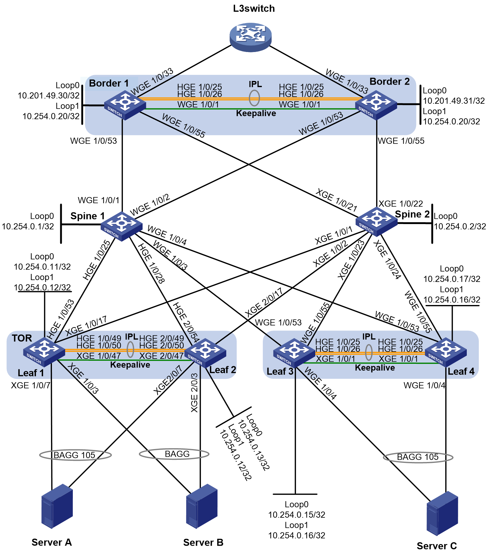
As shown in Figure 1, deploy a DR system at the border tier, and deploy two DR systems at the leaf tier. Configure the network as follows:
· Configure Ethernet aggregate links as IPLs.
· Set up one border DR system with two switches, and configure the DR system as the distributed gateway.
· Configure two switches as spine devices. Configure them as route reflectors to reflect BGP EVPN routes among border and leaf devices.
· Set up two leaf DR systems, each containing two switches. Configure the leaf DR systems as the EVPN access devices of network overlay (such as bare metal servers).
· Configure BGP as the underlay routing protocol.
|
Device |
Interface |
IP address |
Remarks |
|
Leaf 1 |
XGE1/0/7 |
N/A |
Member port of a DR interface, interface with ACs configured. Connected to bare metal server A. |
|
XGE1/0/3 |
N/A |
Member port of a DR interface, interface with ACs configured. Connected to bare metal server B. |
|
|
HGE1/0/49 |
N/A |
Member port of the IPP. Connected to HGE2/0/49 on Leaf 2. |
|
|
HGE1/0/50 |
N/A |
Member port of the IPP. Connected to HGE2/0/50 on Leaf 2. |
|
|
XGE1/0/47 |
172.16.0.1/30 |
Keepalive link Leaf 2: XGE2/0/47 |
|
|
HGE1/0/53 |
10.254.1.2/30 |
Spine 1: HGE1/0/25 |
|
|
XGE1/0/17 |
10.254.1.6/30 |
Spine 2: XGE1/0/1 |
|
|
Loopback0 |
10.254.0.11/32 |
VTEP IP address Connected to a BGP EVPN peer |
|
|
Loopback1 |
10.254.0.12/32 |
Virtual VTEP IP address. |
|
|
Vlan-interface100 |
10.1.1.1/30 |
Interface for east-west traffic forwarding. |
|
|
Leaf 2 |
XGE2/0/7 |
N/A |
Member port of a DR interface, interface with ACs configured. Connected to bare metal server A |
|
XGE2/0/3 |
N/A |
Member port of a DR interface, interface with ACs configured. Connected to bare metal server B |
|
|
HGE2/0/49 |
N/A |
IPP link Leaf 1: HGE1/0/49 |
|
|
HGE2/0/50 |
N/A |
IPP link Leaf 1: HGE1/0/50 |
|
|
XGE2/0/47 |
172.16.0.2/30 |
Keepalive link Leaf 1: XGE1/0/47 |
|
|
HGE2/0/54 |
10.254.1.10/30 |
Spine 1: HGE1/0/28 |
|
|
XGE2/0/17 |
10.254.1.14/30 |
Spine 2: XGE1/0/2 |
|
|
Loopback0 |
10.254.0.13/32 |
VTEP IP address Connected to a BGP EVPN peer. |
|
|
Loopback1 |
10.254.0.12/32 |
Virtual VTEP IP address. |
|
|
Vlan-interface100 |
10.1.1.2/30 |
Interface for east-west traffic forwarding. |
|
|
Leaf 3 |
WGE1/0/4 |
N/A |
Member port of a DR interface, interface with ACs configured. Server C |
|
HGE1/0/25 |
N/A |
IPP link Leaf 4: HGE1/0/25 |
|
|
HGE1/0/26 |
N/A |
IPP link Leaf 4: HGE1/0/26 |
|
|
WGE1/0/1 |
173.16.1.1/30 |
Keepalive link Leaf 4: WGE1/0/1 |
|
|
WGE1/0/53 |
10.254.2.2/30 |
Spine 1: WGE1/0/3 |
|
|
WGE1/0/55 |
10.254.2.6/30 |
Spine 2: XGE1/0/23 |
|
|
Loopback0 |
10.254.0.15/32 |
VTEP IP address Connected to a BGP EVPN peer |
|
|
Loopback1 |
10.254.0.16/32 |
Virtual VTEP IP address |
|
|
Vlan-interface100 |
10.1.2.1/30 |
Interface for east-west traffic forwarding. |
|
|
Leaf 4 |
WGE1/0/4 |
N/A |
Member port of a DR interface, interface with ACs configured. Bare metal server C |
|
HGE1/0/25 |
N/A |
IPP link Leaf 3: HGE1/0/25 |
|
|
HGE1/0/26 |
N/A |
IPP link Leaf 3: HGE1/0/26 |
|
|
WGE1/0/1 |
173.16.1.2/30 |
Keepalive link Leaf 3: WGE1/0/1 |
|
|
WGE1/0/53 |
10.254.2.10/30 |
Spine 1: WGE1/0/4 |
|
|
WGE1/0/55 |
10.254.2.14/30 |
Spine 2: XGE1/0/24 |
|
|
Loopback0 |
10.254.0.17/32 |
VTEP IP address Connected to a BGP EVPN peer |
|
|
Loopback1 |
10.254.0.16/32 |
Virtual VTEP IP address |
|
|
Vlan-interface100 |
10.1.2.2/30 |
Interface for east-west traffic forwarding. |
|
|
Spine 1 |
HGE1/0/25 |
10.254.1.1/30 |
Leaf 1: HGE1/0/53 |
|
HGE1/0/28 |
10.254.1.9/30 |
Leaf 2: HGE2/0/54 |
|
|
WGE1/0/3 |
10.254.2.1/30 |
Leaf 3: WGE1/0/53 |
|
|
WGE1/0/4 |
10.254.2.9/30 |
Leaf 4: WGE1/0/53 |
|
|
WGE1/0/1 |
10.254.7.1/30 |
Border 1: WGE1/0/53 |
|
|
WGE1/0/2 |
10.254.7.5/30 |
Border 2: WGE1/0/53 |
|
|
LoopBack0 |
10.254.0.1/32 |
VTEP IP address Connected to a BGP EVPN peer |
|
|
Spine 2 |
XGE1/0/1 |
10.254.1.5/30 |
Leaf 1: XGE1/0/17 |
|
XGE1/0/2 |
10.254.1.13/30 |
Leaf 2: XGE2/0/17 |
|
|
XGE1/0/23 |
10.254.2.5/30 |
Leaf 3: WGE1/0/55 |
|
|
XGE1/0/24 |
10.254.2.13/30 |
Leaf 4: WGE1/0/55 |
|
|
XGE1/0/21 |
10.254.7.21/30 |
Border 1: WGE1/0/55 |
|
|
XGE1/0/22 |
10.254.7.25/30 |
Border 2: WGE1/0/55 |
|
|
LoopBack0 |
10.254.0.2/32 |
VTEP IP address Connected to a BGP EVPN peer |
|
|
Border1 |
WGE1/0/53 |
10.254.7.2/30 |
Spine 1: WGE1/0/1 |
|
WGE1/0/55 |
10.254.7.22/30 |
Spine 2: XGE1/0/21 |
|
|
HGE1/0/25 |
N/A |
IPP link Border 2: HGE1/0/25 |
|
|
HGE1/0/26 |
N/A |
IPP link Border 2: HGE1/0/26 |
|
|
WGE1/0/1 |
174.16.2.1/30 |
Keepalive link Border2: WGE1/0/1 |
|
|
WGE1/0/33 |
192.101.1.1/31 |
L3switch |
|
|
LoopBack0 |
10.201.49.30/32 |
ED IP |
|
|
LoopBack1 |
10.254.0.20/32 |
Virtual ED IP |
|
|
Vlan-interface100 |
100.1.1.1/31 |
Interface for east-west traffic forwarding. |
|
|
Border2 |
WGE1/0/53 |
10.254.7.6/30 |
Spine 1: WGE1/0/2 |
|
WGE1/0/55 |
10.254.7.26/30 |
Spine 2: XGE1/0/22 |
|
|
HGE1/0/25 |
N/A |
IPP link Border 2: HGE1/0/25 |
|
|
HGE1/0/26 |
N/A |
IPP link Border 2: HGE1/0/26 |
|
|
WGE1/0/1 |
174.16.2.2/30 |
Keepalive link Border2: WGE1/0/1 |
|
|
WGE1/0/33 |
192.101.1.3/31 |
L3switch |
|
|
LoopBack0 |
10.201.49.31/32 |
ED IP |
|
|
LoopBack1 |
10.254.0.20/32 |
Virtual ED IP |
|
|
Vlan-interface100 |
100.1.1.2/31 |
Interface for east-west traffic forwarding. |
Traffic forwarding models
A bare metal host is called a PM in network overlay. The following traffic forwarding models are available:
· PM-to-PM Layer 2 communication through the same DR system at the leaf tier.
· PM-to-PM Layer 3 communication through the same DR system at the leaf tier.
· PM-to-PM Layer 2 communication across DR systems at the leaf tier.
· PM-to-PM Layer 3 communication across DR systems at the leaf tier.
· Layer 3 communication between PMs and the external network.
Applicable product matrix
|
|
IMPORTANT: In addition to running an applicable software version, you must also install the most recent patch, if any. |
|
Device |
Software version |
|
|
Spine |
S12500X-AF S12500X-AF switches are used in this example. |
R2820 |
|
S12500G-AF |
R7624P12 |
|
|
Leaf or border |
S6800, S6860 S6800 switches are used in this configuration example. |
Under development. To obtain the latest images, contact Technical Support. |
|
S6812, S6813 S6812 and S6813 switches can only be used as leaf devices. |
Under development. To obtain the latest images, contact Technical Support. |
|
|
S6805, S6825, S6850, and S9850 S6850 switches are used in this configuration example. |
R6635 |
|
|
S6890 |
R2820 |
|
|
S9820-64H (EVPN gateway not supported) S9820-8C |
Not supported |
|
|
SDN controller |
N/A |
Obtain the most recent version. |
Restrictions and guidelines
· By default, if a DR system uses an Ethernet aggregate link as the IPL, each DR member device creates a dynamic AC on the IPL when an AC is configured on a site-facing interface. The dynamic AC and the site-facing AC have the same frame match criteria and VSI mapping. If two site-facing ACs on different interfaces have the same frame match criteria but different VSI mappings, the dynamic ACs created for the site-facing ACs will conflict with each other. To prevent this issue, execute the l2vpn drni peer-link ac-match-rule vxlan-mapping command to enable the DR member devices to create frame match criteria based on VXLAN IDs for the dynamic ACs on the IPL.
· If you use a VXLAN tunnel as the IPL in an EVPN environment, you must retain a large number of logical interfaces (for example, tunnel and loopback interfaces) in up state. To reduce configuration steps, set the default DRNI MAD action to NONE and execute the drni mad include interface command to specify interfaces that must be shut down by DRNI MAD in addition to those already automatically specified by the system.
· If you use two border devices to set up a DR system, unidirectional tunnels exist between the ToR switches or between the ToR switch and SDN gateway. Typically, unidirectional tunnels are set up when a ToR switch is disconnected from the controller or new BMs come online. In this scenario, an online ToR switch advertises routes that contain its real IP address. The SDN will set up a tunnel to that real IP address, while the ToR switch uses the virtual VTEP IP address for tunnel setup. For the ToR switches to decapsulate the packets sent by the SDN gateway or other ToR switches, execute the vxlan default-decapsulation source interface command to enable default VXLAN decapsulation on the ToR switches.
Configuring S6800 switches as leaf devices
Procedure summary
· Configuring the resource mode
· Configuring an underlay BGP instance
· Configuring the links towards the spine tier
· Configuring the links towards the bare metal servers
· Configuring an EVPN BGP instance (controller-deployed)
· Configuring the overlay network
Configuring the resource mode
|
Leaf 1 |
Leaf 2 |
Configuration method |
Description |
Purpose |
Remarks |
|
hardware-resource switch-mode 4 |
hardware-resource switch-mode 4 |
Manual |
Set the hardware resource mode for the MAC address table, ARP/ND table, and routing tables. |
Adjust the capacities of the MAC address table, ARP/ND table, and routing tables. |
Reboot the device for this setting to take effect. |
|
hardware-resource routing-mode ipv6-128 |
hardware-resource routing-mode ipv6-128 |
Manual |
Configure the hardware resource mode as IPv6-128 routing mode. |
N/A |
Reboot the device for this setting to take effect. |
|
hardware-resource vxlan l3gw40k |
hardware-resource vxlan l3gw40k |
Manual |
Set the VXLAN hardware resource mode to Layer 3 gateway mode that supports 40 K of overlay adjacency table |
N/A |
Reboot the device for this setting to take effect. |
Configuring an underlay BGP instance
|
Leaf 1 |
Leaf 2 |
Configuration method |
Description |
Purpose |
Remarks |
|
router id 10.254.0.11 |
router id 10.254.0.13 |
Manual |
Configure the IP address of Loopback 0 as the router ID. |
Configure the global router ID. |
N/A |
|
bgp 65001 |
bgp 65002 |
Manual |
Enter BGP view. |
N/A |
N/A |
|
bgp update-delay on-startup 100 |
bgp update-delay on-startup 100 |
Manual |
Configure BGP to delay sending route updates on reboot. |
Avoid forwarding issues during fallback after a ToR switch restarts. |
N/A |
|
router-id 10.254.0.11 |
router-id 10.254.0.13 |
Manual |
Configure a router ID for the BGP instance. |
To run BGP in a BGP instance, you must configure a router ID for the BGP instance. If you do not configure a router ID for the BGP instance, it uses the global router ID. |
N/A |
|
group spines internal |
group spines internal |
Manual |
Create an IBGP peer group. |
N/A |
N/A |
|
peer spines route-update-interval 0 |
peer spines route-update-interval 0 |
Manual |
Specify an interval for sending the same update to the peer group. |
Enable the device to immediately send update to the peer group upon route changes to speed up route convergence after a DR primary/secondary switchover occurs. |
Execute this command only for IBGP peers. |
|
peer 10.254.1.1 group spines |
peer 10.254.1.9 group spines |
Manual |
Add a spine device to the peer group. |
N/A |
N/A |
|
peer 10.254.1.5 group spines |
peer 10.254.1.13 group spines |
Manual |
Add a spine device to the peer group. |
N/A |
N/A |
|
peer 10.1.1.2 as-number 65002 |
peer 10.1.1.1 as-number 65001 |
Manual |
Configure an EBGP peer. |
N/A |
N/A |
|
address-family ipv4 unicast |
address-family ipv4 unicast |
Manual |
Enter IPv4 unicast address family view. |
N/A |
N/A |
|
balance 8 |
balance 8 |
Manual |
Set the maximum number of BGP ECMP routes for load balancing. |
N/A |
N/A |
|
import-route direct |
import-route direct |
Manual |
Configure BGP to redistribute direct routes. |
N/A |
N/A |
|
peer spines enable |
peer spines enable |
Manual |
Enable BGP to exchange routing information with a peer or peer group. |
N/A |
N/A |
|
peer 10.1.1.2 enable |
peer 10.1.1.1 enable |
Manual |
Enable BGP to exchange routing information with a peer or peer group. |
N/A |
N/A |
|
quit |
quit |
Manual |
Return to IPv4 address family view |
N/A |
N/A |
|
quit |
quit |
Manual |
Return to system view. |
N/A |
N/A |
|
interface LoopBack0 |
interface LoopBack0 |
Manual |
Create Loopback 0 and enter its view. |
N/A |
N/A |
|
ip address 10.254.0.11 255.255.255.255 |
ip address 10.254.0.13 255.255.255.255 |
Manual |
Assign an IP address to the interface. |
VTEP IP |
N/A |
|
quit |
quit |
Manual |
Return to system view. |
N/A |
N/A |
|
interface LoopBack1 |
interface LoopBack1 |
Manual |
Create Loopback 0 and enter its view. |
N/A |
N/A |
|
ip address 10.254.0.12 255.255.255.255 |
ip address 10.254.0.12 255.255.255.255 |
Manual |
Assign an IP address to the interface. |
Virtual VTEP IP |
N/A |
|
quit |
quit |
Manual |
Return to system view. |
N/A |
N/A |
|
vlan 10 |
vlan 10 |
Manual |
Create a VLAN. |
Create the VLAN for communicating with the DR peer. |
N/A |
|
interface Vlan-interface10 |
interface Vlan-interface10 |
Manual |
Create VLAN-interface 10. |
Create the VLAN interface for the VLAN used for communicating with the DR peer. When the uplink interface fails, the device forwards the packets received on the DR interfaces to the DR peer for Layer 3 forwarding. |
N/A |
|
ip address 10.1.1.1 255.255.255.0 |
ip address 10.1.1.2 255.255.255.0 |
Manual |
Assign an IP address to the interface. |
N/A |
N/A |
|
quit |
quit |
Manual |
Return to system view. |
N/A |
N/A |
Configuring the links towards the spine tier
|
Leaf 1 |
Leaf 2 |
Configuration method |
Description |
Purpose |
Remarks |
|
interface HundredGigE1/0/53 |
interface HundredGigE2/0/54 |
Manual |
Configure the interface connected to Spine 1. |
N/A |
N/A |
|
port link-mode route |
port link-mode route |
Manual |
Configure the Ethernet interface to work in Layer 3 mode. |
N/A |
N/A |
|
ip address 10.254.1.2 255.255.255.252 |
ip address 10.254.1.10 255.255.255.252 |
Manual |
Assign an IP address to the interface. |
N/A |
N/A |
|
undo mac-address static source-check enable |
undo mac-address static source-check enable |
Manual |
Disable static source check. |
To correctly forward traffic sourced from the MAC address of a VLAN interface, you must disable the static source check feature on the Layer 2 interfaces in the VLAN. |
N/A |
|
interface Ten-GigabitEthernet 1/0/17 |
interface Ten-GigabitEthernet 2/0/17 |
Manual |
Configure the interface connecting to Spine 2. |
N/A |
N/A |
|
port link-mode route |
port link-mode route |
Manual |
Configure the interface as a Layer 3 interface. |
N/A |
N/A |
|
ip address 10.254.1.6 255.255.255.252 |
ip address 10.254.1.14 255.255.255.252 |
Manual |
Assign an IP address to the interface. |
N/A |
N/A |
|
undo mac-address static source-check enable |
undo mac-address static source-check enable |
Manual |
Disable static source check. |
To correctly forward traffic sourced from the MAC address of a VLAN interface, you must disable the static source check feature on the Layer 2 interfaces in the VLAN. |
N/A |
Configuring L2VPN
|
Leaf 1 |
Leaf 2 |
Configuration method |
Description |
Purpose |
Remarks |
|
l2vpn enable |
l2vpn enable |
Manual |
Enable L2VPN. |
N/A |
N/A |
|
vxlan default-decapsulation source interface LoopBack0 |
vxlan default-decapsulation source interface LoopBack0 |
Manual |
Enable default VXLAN decapsulation on the packets destined for the VTEP IP address. |
Execute this command in unidirectional tunnel scenarios. |
This command takes effect only when the specified interface has an IP address. |
|
vxlan tunnel mac-learning disable |
vxlan tunnel mac-learning disable |
Manual |
Disable remote-MAC address learning. |
Execute this command if a controller issues forwarding entries to the device. |
N/A |
|
vxlan tunnel arp-learning disable |
vxlan tunnel arp-learning disable |
Manual |
Disable remote ARP learning. |
Execute this command if a controller issues forwarding entries to the device. |
N/A |
|
mac-address timer aging 3600 |
mac-address timer aging 3600 |
Manual |
Set the aging time to 3600 seconds for dynamic MAC address entries. |
Increase this timer to ensure forwarding entry synchronization is finished in time after the DR peer restarts. |
This setting must be consistent on the DR member devices in the same DR system. |
|
arp timer aging 1440 |
arp timer aging 1440 |
Manual |
Set the aging timer for dynamic ARP entries to 1440 minutes. |
Increase this timer to ensure forwarding entry synchronization is finished in time after the DR peer restarts. |
This setting must be consistent on the DR member devices in the same DR system. |
|
|
NOTE: If you use two border devices to set up a DR system and BMs in bond1 mode need to communicate with the external network, unidirectional tunnels exist between the ToR switches and SDN gateway. Typically, unidirectional tunnels are set up when a ToR switch is disconnected from the controller or new BMs come online. In this scenario, an online ToR switch advertises routes that contain its real IP address. The SDN will set up a tunnel to that real IP address, while the ToR switch uses the virtual VTEP IP address for tunnel setup. For the ToR switches to decapsulate the packets sent by the SDN gateway, enable default VXLAN decapsulation on the ToR switches. |
Configuring DRNI
|
Leaf 1 |
Leaf 2 |
Configuration method |
Description |
Purpose |
Remarks |
|
ip vpn-instance mgmt |
ip vpn-instance mgmt |
Manual |
Create a VPN for the management Ethernet interface. |
N/A |
This command is optional. |
|
interface M-GigabitEthernet 0/0/0 |
interface M-GigabitEthernet 0/0/0 |
Manual |
Enter the view of the management Ethernet interface. |
N/A |
N/A |
|
ip binding vpn-instance mgmt |
ip binding vpn-instance mgmt |
Manual |
Assign the management Ethernet interface to the VPN. |
N/A |
Assign the management Ethernet interface to a VPN as needed. |
|
ip address 101.0.186.91 255.255.255.0 |
ip address 101.0.186.90 255.255.255.0 |
Manual |
Configure a management IP address. |
N/A |
N/A |
|
quit |
quit |
Manual |
Return to system view. |
N/A |
N/A |
|
l2vpn drni peer-link ac-match-rule vxlan-mapping |
l2vpn drni peer-link ac-match-rule vxlan-mapping |
Manual |
Enable the device to create frame match criteria based on VXLAN IDs for the dynamic ACs on the Ethernet aggregate link IPL. |
If two site-facing ACs on different interfaces have the same frame match criteria but different VSI mappings, the dynamic ACs created for the site-facing ACs will conflict with each other. Execute this command to resolve this issue. |
N/A |
|
evpn drni group 10.254.0.12 |
evpn drni group 10.254.0.12 |
Manual |
Enable EVPN distributed relay and specify the virtual VTEP address. |
N/A |
You must specify the same virtual VTEP address on both VTEPs in the same DR system. |
|
evpn drni local 10.254.0.11 remote 10.254.0.13 |
evpn drni local 10.254.0.13 remote 10.254.0.11 |
Manual |
Specify the IP addresses of the VTEPs in a DR system. |
After you configure this command, each VTEP in a DR system changes the next hop of the routes for single-armed ACs to its local VTEP IP address when advertising the routes. This ensures that the traffic of a single-armed AC is forwarded to its attached VTEP. |
When you execute this command, make sure the IP address of the local VTEP belongs to a local interface. Make sure the local VTEP IP address and peer VTEP IP address are reversed on the VTEPs in a DR system. |
|
evpn global-mac 0000-0005-0001 |
evpn global-mac 0000-0005-0001 |
Manual |
Configure the EVPN global MAC address. |
N/A |
You must specify the same EVPN global MAC address on the devices in the same DR system. Do not use a reserved MAC address as the EVPN global MAC address. |
|
drni system-mac 0001-0001-0002 |
drni system-mac 0001-0001-0002 |
Manual |
Configure the DR system MAC address. |
Configure the settings required for establishing the DR system. |
The DR system MAC address uniquely identifies the DR system on the network. For the DR member devices to be identified as one DR system, you must configure the same DR system MAC address on them. |
|
drni system-number 1 |
drni system-number 2 |
Manual |
Set the DR system number. |
Configure the settings required for establishing the DR system. |
You must assign different DR system numbers to the DR member devices in a DR system. |
|
drni system-priority 123 |
drni system-priority 123 |
Manual |
Set the DR system priority. |
N/A |
This command is optional. You must configure the same DR system priority for the DR member devices in a DR system. The default DR system priority is 32768. The smaller the priority value, the higher the priority. |
|
drni keepalive ip destination 172.16.0.2 source 172.16.0.1 |
drni keepalive ip destination 172.16.0.1 source 172.16.0.2 |
Manual |
Configure DR keepalive packet parameters. |
N/A |
You do not need to specify a VPN instance if the interface does not belong to any VPN instance. If the interface that owns the source IP address is not excluded from the DRNI MAD DOWN action, exclude it from that action. |
|
drni mad default-action none |
drni mad default-action none |
Manual |
Set the default DRNI MAD action to NONE. |
N/A |
N/A |
|
drni mad include interface HundredGigE1/0/53 |
drni mad include interface HundredGigE2/0/52 |
Manual |
Enable DRNI to shut down an interface when the DR system splits. |
Shut down the interface upon a DR system split to reduce the fallback duration after a device restart. |
Execute this command on the uplink interface attached to a spine device. |
|
drni mad include interface Ten-GigabitEthernet 1/0/17 |
drni mad include interface Ten-GigabitEthernet 2/0/17 |
Manual |
Enable DRNI to shut down an interface when the DR system splits. |
Shut down the interface upon a DR system split to reduce the fallback duration after a device restart. |
Execute this command on the uplink interface attached to a spine device. |
|
drni restore-delay 200 |
drni restore-delay 200 |
Manual |
Set the data restoration interval. |
Ensure that entry synchronization is finished before interfaces are brought up. |
N/A |
|
interface Bridge-Aggregation1 |
interface Bridge-Aggregation1 |
Manual |
Create Bridge-Aggregation 1 which will be the IPP. |
N/A |
N/A |
|
port link-type trunk |
port link-type trunk |
Manual |
Set the link type of the interface to trunk. |
N/A |
N/A |
|
port trunk permit vlan all |
port trunk permit vlan all |
Manual |
Configure the trunk interface to permit all VLANs. |
N/A |
N/A |
|
link-aggregation mode dynamic |
link-aggregation mode dynamic |
Manual |
Configure the aggregate interface to operate in dynamic mode and enable LACP. |
N/A |
N/A |
|
port drni intra-portal-port 1 |
port drni intra-portal-port 1 |
Manual |
Configure the interface as the IPP. |
N/A |
N/A |
|
undo mac-address static source-check enable |
undo mac-address static source-check enable |
Manual |
Disable static source check. |
To correctly forward traffic sourced from the MAC address of a VLAN interface, you must disable the static source check feature on the Layer 2 interfaces in the VLAN. |
You do not need to execute this command on S12500X-AF switches. Disable static source check on the IPP and the uplink interfaces attached to spine devices. |
|
interface FortyGigE1/0/49 |
interface FortyGigE2/0/49 |
Manual |
Configure the interface as a member port of the IPP. |
N/A |
N/A |
|
port link-type trunk |
port link-type trunk |
Manual |
Set the link type of the interface to trunk. |
N/A |
N/A |
|
port trunk permit vlan all |
port trunk permit vlan all |
Manual |
Configure the trunk interface to permit all VLANs. |
N/A |
N/A |
|
port link-aggregation group 1 |
port link-aggregation group 1 |
Manual |
Assign the interface to link aggregation group 1. |
N/A |
N/A |
|
interface FortyGigE1/0/50 |
interface FortyGigE2/0/50 |
Manual |
Configure the interface as a member port of the IPP. |
N/A |
N/A |
|
port link-type trunk |
port link-type trunk |
Manual |
Set the link type of the interface to trunk. |
N/A |
N/A |
|
port trunk permit vlan all |
port trunk permit vlan all |
Manual |
Configure the trunk interface to permit all VLANs. |
N/A |
N/A |
|
port link-aggregation group 1 |
port link-aggregation group 1 |
Manual |
Assign the interface to link aggregation group 1. |
N/A |
N/A |
|
quit |
quit |
Manual |
Return to system view. |
N/A |
N/A |
Configuring the links towards the bare metal servers
|
Leaf 1 |
Leaf 2 |
Configuration method |
Description |
Purpose |
Remarks |
|
interface Bridge-Aggregation105 |
interface Bridge-Aggregation105 |
Manual |
Create an aggregate interface to be configured as a DR interface. |
Create the aggregate interface to connect to the bare metal servers. |
N/A |
|
port link-type trunk |
port link-type trunk |
Manual |
Set the link type of the interface to trunk. |
N/A |
N/A |
|
link-aggregation mode dynamic |
link-aggregation mode dynamic |
Manual |
Configure the aggregate interface to operate in dynamic mode and enable LACP. |
N/A |
N/A |
|
port drni group 105 |
port drni group 105 |
Manual |
Assign the aggregate interface to a DR group. |
N/A |
N/A |
|
interface Ten-GigabitEthernet1/0/7 |
interface Ten-GigabitEthernet 2/0/7 |
Manual |
Enter the view of a member port to be assigned to the DR interface. |
N/A |
N/A |
|
port link-type trunk |
port link-type trunk |
Manual |
Set the link type of the interface to trunk. |
N/A |
N/A |
|
port link-aggregation group 105 |
port link-aggregation group 105 |
Manual |
Assign the interface to the aggregation group of the DR interface. |
N/A |
N/A |
|
quit |
quit |
Manual |
Return to system view. |
N/A |
N/A |
Configuring spanning tree
|
Leaf 1 |
Leaf 2 |
Configuration method |
Description |
Purpose |
|
stp global enable |
stp global enable |
Manual |
Enable spanning tree globally. |
N/A |
|
interface Bridge-Aggregation 105 |
interface Bridge-Aggregation 105 |
Manual |
Enter the view of the DR interface connected to the bare metal servers. |
N/A |
|
stp edged-port |
stp edged-port |
Manual |
Configure the interface as an edge port. |
Exclude the interface from spanning tree calculation. |
|
|
NOTE: Make sure the DR member devices have the same spanning tree configuration, including: · Global spanning tree configuration. · Spanning tree configuration on the IPP. · Spanning tree configuration on DR interfaces. Violation of this rule might cause network flapping. IPPs in the DR system do not participate in spanning tree calculation. The DR member devices still use the DR system MAC address after the DR system splits, which will cause spanning tree calculation issues. To avoid the issues, enable DRNI standalone mode on the DR member devices before the DR system splits. |
Configuring an EVPN BGP instance (controller-deployed)
|
Leaf 1 |
Leaf 2 |
Configuration method |
Description |
Purpose |
Remarks |
|
bgp 65010 instance EVPN |
bgp 65010 instance EVPN |
Manual |
Enable a BGP instance. |
N/A |
N/A |
|
bgp update-delay on-startup 150 |
bgp update-delay on-startup 150 |
Manual |
Configure BGP to delay sending route updates on reboot. |
Avoid forwarding issues during fallback after a ToR switch restarts. |
N/A |
|
router-id 10.254.0.11 |
router-id 10.254.0.13 |
Manual |
Configure a router ID for the BGP instance. |
To run BGP in a BGP instance, you must configure a router ID for the BGP instance. If you do not configure a router ID for the BGP instance, it uses the global router ID. |
N/A |
|
group evpn internal |
group evpn internal |
Manual |
Create an IBGP peer group. |
N/A |
N/A |
|
peer evpn connect-interface LoopBack0 |
peer evpn connect-interface LoopBack0 |
Manual |
Specify a source interface for establishing TCP links towards the peer group. |
N/A |
N/A |
|
peer evpn route-update-interval 0 |
peer evpn route-update-interval 0 |
Manual |
Specify an interval for sending the same update to the peer group. |
Enable the device to fast send update to the peer group upon route changes to speed up route convergence after a DR primary/secondary switchover occurs. |
Execute this command only for IBGP peers. |
|
peer 10.254.0.1 group evpn |
peer 10.254.0.1 group evpn |
Manual |
Add a spine device to the peer group. |
N/A |
N/A |
|
peer 10.254.0.2 group evpn |
peer 10.254.0.2 group evpn |
Manual |
Add a spine device to the peer group. |
N/A |
N/A |
|
address-family l2vpn evpn |
address-family l2vpn evpn |
Manual |
Enter EVPN address family view. |
N/A |
N/A |
|
peer evpn enable |
peer evpn enable |
Manual |
Enable the device to exchange routes with the peer group. |
N/A |
N/A |
|
quit |
quit |
Manual |
Return to system view. |
N/A |
N/A |
Configuring the overlay network
|
Leaf 1 |
Leaf 2 |
Configuration method |
Description |
Remarks |
|
ip vpn-instance Core_VRF |
ip vpn-instance Core_VRF |
Controller-based |
Create a VPN instance on the private network. |
N/A |
|
route-distinguisher 65131:10 |
route-distinguisher 65132:10 |
Controller-based |
Configure the RD of the VPN instance. |
N/A |
|
address-family ipv4 |
address-family ipv4 |
Controller-based |
Enter IPv4 address family view of the VPN instance. |
N/A |
|
vpn-target 65131:10 65040:10 import-extcommunity |
vpn-target 65132:10 65040:10 import-extcommunity |
Controller-based |
Configure import targets for the VPN instance. |
N/A |
|
vpn-target 65131:10 export-extcommunity |
vpn-target 65132:10 export-extcommunity |
Controller-based |
Configure export targets for the VPN instance. |
N/A |
|
address-family evpn |
address-family evpn |
Controller-based |
Enter EVPN view of the VPN instance. |
N/A |
|
vpn-target 65131:10 65040:10 import-extcommunity |
vpn-target 65132:10 65040:10 import-extcommunity |
Controller-based |
Configure import targets for the VPN instance. |
N/A |
|
vpn-target 65131:10 export-extcommunity |
vpn-target 65132:10 export-extcommunity |
Controller-based |
Configure export targets for the VPN instance. |
N/A |
|
quit |
quit |
Controller-based |
Return to VPN instance view. |
N/A |
|
quit |
quit |
Controller-based |
Return to VPN instance view. |
N/A |
|
interface Vsi-interface1303 |
interface Vsi-interface1303 |
Controller-based |
Create a VSI interface and enter its view. |
N/A |
|
mtu 1450 |
mtu 1450 |
Controller-based |
Configure the MTU of the VSI interface. |
N/A |
|
ip binding vpn-instance Core_VRF |
ip binding vpn-instance Core_VRF |
Controller-based |
Associate the VSI interface with the VPN instance. |
N/A |
|
ip address 10.201.54.33 255.255.255.224 |
ip address 10.201.54.33 255.255.255.224 |
Controller-based |
Assign an IPv4 address as a gateway address to the VSI interface. |
Make sure the VSI interface has the same setting for this command on all distributed gateways. |
|
mac-address 0000-0001-1303 |
mac-address 0000-0001-1303 |
Controller-based |
Assign a MAC address to the VSI interface. |
Make sure the VSI interface has the same setting for this command on all distributed gateways. |
|
distributed-gateway local |
distributed-gateway local |
Controller-based |
Specify the VSI interface as a distributed gateway to provide services for the local site. |
N/A |
|
quit |
quit |
Controller-based |
Return to system view. |
N/A |
|
interface Vsi-interface10000 |
interface Vsi-interface10000 |
Controller-based |
Create a VSI interface and enter its view. |
N/A |
|
ip binding vpn-instance Core_VRF |
ip binding vpn-instance Core_VRF |
Controller-based |
Associate the VSI interface with a VPN instance. |
N/A |
|
l3-vni 10000 |
l3-vni 10000 |
Controller-based |
Assign an L3VNI to the VSI interface. |
The L3VNI is shared among the VSI interfaces associated with the same VPN instance. |
|
quit |
quit |
Controller-based |
Return to system view. |
N/A |
|
vsi Core_VRF-1303 |
vsi Core_VRF-1303 |
Controller-based |
Create a VSI and enter its view. |
N/A |
|
gateway vsi-interface 1303 |
gateway vsi-interface 1303 |
Controller-based |
Specify a gateway interface for the VSI. |
N/A |
|
vxlan 1303 |
vxlan 1303 |
Controller-based |
Create a VXLAN and enter its view. |
N/A |
|
evpn encapsulation vxlan |
evpn encapsulation vxlan |
Controller-based |
Create an EVPN instance and enter its view. |
N/A |
|
route-distinguisher auto |
route-distinguisher auto |
Controller-based |
Configure the RD of the EVPN instance. |
N/A |
|
vpn-target auto export-extcommunity |
vpn-target auto export-extcommunity |
Controller-based |
Configure export targets for EVPN. |
N/A |
|
vpn-target auto import-extcommunity |
vpn-target auto import-extcommunity |
Controller-based |
Configure import targets for EVPN. |
N/A |
|
quit |
quit |
Controller-based |
Return to VSI view |
N/A |
|
quit |
quit |
Controller-based |
Return to system view. |
- |
|
interface Bridge-Aggregation105 |
interface Bridge-Aggregation105 |
Controller-based |
Enter the view of the interface to be configured with ACs. |
N/A |
|
port link-type trunk |
port link-type trunk |
Controller-based |
Set the link type of the interface to trunk. |
N/A |
|
undo port trunk permit vlan 1 |
undo port trunk permit vlan 1 |
Controller-based |
Remove the trunk interface from VLAN 1. |
N/A |
|
port trunk permit vlan 1303 |
port trunk permit vlan 1303 |
Controller-based |
Assign the trunk interface to VLAN 1303. |
N/A |
|
link-aggregation mode dynamic |
link-aggregation mode dynamic |
Controller-based |
Configure the aggregate interface to operate in dynamic mode and enable LACP. |
N/A |
|
port drni group 105 |
port drni group 105 |
Controller-based |
Assign the interface to a DR group. |
N/A |
|
service-instance 1303 |
service-instance 1303 |
Controller-based |
Create an Ethernet service instance and enter its view. |
N/A |
|
encapsulation s-vid 1303 |
encapsulation s-vid 1303 |
Controller-based |
Configure the Ethernet service instance to match traffic by the outer VLAN ID. |
N/A |
|
xconnect vsi Core_VRF-1303 |
xconnect vsi Core_VRF-1303 |
Controller-based |
Map the Ethernet service instance to the VSI created previously. |
N/A |
|
quit |
quit |
Controller-based |
Return to system view. |
N/A |
Configuring S6850 switches as leaf devices
Procedure summary
· Configuring the resource mode
· Configuring the underlay BGP instance
· Configuring the links towards the spine tier
· Configuring the links towards the bare metal servers
· Configuring an EVPN BGP instance
· Configuring the overlay network
Configuring the resource mode
|
Leaf 3 |
Leaf 4 |
Configuration method |
Description |
Purpose |
Remarks |
|
hardware-resource switch-mode DUAL-STACK |
hardware-resource switch-mode DUAL-STACK |
Manual |
Set the hardware resource mode to DUAL-STACK for the MAC address table, ARP/ND table, and routing tables |
Adjust the capacities of the MAC address table, ARP/ND table, and routing tables. |
Reboot the device for this setting to take effect. |
|
hardware-resource routing-mode ipv6-128 |
hardware-resource routing-mode ipv6-128 |
Manual |
Enable support for IPv6 routes with prefixes longer than 64 bits. |
N/A |
Reboot the device for this setting to take effect. |
|
hardware-resource vxlan l3gw |
hardware-resource vxlan l3gw |
Manual |
Set the VXLAN hardware resource mode to Layer 3 gateway mode that supports 40 K of overlay adjacency table |
N/A |
Reboot the device for this setting to take effect. |
Configuring the underlay BGP instance
|
Leaf 3 |
Leaf 4 |
Configuration method |
Description |
Purpose |
Remarks |
|
router id 10.254.0.15 |
router id 10.254.0.17 |
Manual |
Configure the IP address of Loopback 0 as the router ID. |
Configure the global router ID. |
N/A |
|
bgp 65003 |
bgp 65004 |
Manual |
Enter BGP view. |
N/A |
N/A |
|
bgp update-delay on-startup 100 |
bgp update-delay on-startup 100 |
Manual |
Configure BGP to delay sending route updates on reboot. |
Avoid forwarding issues during fallback after a ToR switch restarts. |
N/A |
|
router-id 10.254.0.15 |
router-id 10.254.0.17 |
Manual |
Configure a router ID for the BGP instance. |
To run BGP in a BGP instance, you must configure a router ID for the BGP instance. If you do not configure a router ID for the BGP instance, it uses the global router ID. |
N/A |
|
group spines internal |
group spines internal |
Manual |
Create an IBGP peer group. |
N/A |
N/A |
|
peer spines route-update-interval 0 |
peer spines route-update-interval 0 |
Manual |
Specify an interval for sending the same update to the peer group. |
Configure BGP to immediately send route updates to a peer or peer group. |
Execute this command on only IBGP peers. |
|
peer 10.254.2.1 group spines |
peer 10.254.2.9 group spines |
Manual |
Add a spine device to the peer group. |
N/A |
N/A |
|
peer 10.254.2.5 group spines |
peer 10.254.2.13 group spines |
Manual |
Add a spine device to the peer group. |
N/A |
N/A |
|
peer 10.1.2.2 as-number 65004 |
peer 10.1.2.1 as-number 65003 |
Manual |
Configure an EBGP peer. |
N/A |
N/A |
|
address-family ipv4 unicast |
address-family ipv4 unicast |
Manual |
Enter IPv4 address family view. |
N/A |
N/A |
|
balance 8 |
balance 8 |
Manual |
Set the maximum number of BGP ECMP routes for load balancing. |
N/A |
N/A |
|
import-route direct |
import-route direct |
Manual |
Configure BGP to redistribute direct routes. |
N/A |
N/A |
|
peer spines enable |
peer spines enable |
Manual |
Enable BGP to exchange routing information with a peer or peer group. |
N/A |
N/A |
|
peer 10.1.2.2 enable |
peer 10.1.2.1 enable |
Manual |
Enable BGP to exchange routing information with a peer or peer group. |
N/A |
N/A |
|
quit |
quit |
Manual |
Return to BGP view. |
N/A |
N/A |
|
quit |
quit |
Manual |
Return to system view. |
N/A |
N/A |
|
interface LoopBack0 |
interface LoopBack0 |
Manual |
Create Loopback 0 and enter its view. |
N/A |
N/A |
|
ip address 10.254.0.15 255.255.255.255 |
ip address 10.254.0.17 255.255.255.255 |
Manual |
Assign an IP address to the interface. |
VTEP IP |
- |
|
quit |
quit |
Manual |
Return to system view. |
N/A |
N/A |
|
interface LoopBack1 |
interface LoopBack1 |
Manual |
Create Loopback 0 and enter its view. |
N/A |
N/A |
|
ip address 10.254.0.16 255.255.255.255 |
ip address 10.254.0.16 255.255.255.255 |
Manual |
Assign an IP address to the interface. |
Virtual VTEP IP |
- |
|
quit |
quit |
Manual |
Return to system view. |
N/A |
N/A |
|
vlan 10 |
vlan 10 |
Manual |
Create VLAN 10. |
Create the VLAN for communicating with the DR peer. |
N/A |
|
interface Vlan-interface10 |
interface Vlan-interface10 |
Manual |
Create VLAN-interface 10. |
Create the VLAN interface for the VLAN used for communicating with the DR peer. When the uplink interface fails, the device forwards the packets received on the DR interfaces to the DR peer for Layer 3 forwarding. |
N/A |
|
ip address 10.1.2.1 255.255.255.0 |
ip address 10.1.2.2 255.255.255.0 |
Manual |
Assign an IP address to the interface. |
N/A |
N/A |
|
quit |
quit |
Manual |
Return to system view. |
N/A |
N/A |
Configuring the links towards the spine tier
|
Leaf 3 |
Leaf 4 |
Configuration method |
Description |
Purpose |
Remarks |
|
interface Twenty-FiveGigE1/0/53 |
interface Twenty-FiveGigE1/0/53 |
Manual |
Configure the interface connected to Spine 1. |
N/A |
N/A |
|
port link-mode route |
port link-mode route |
Manual |
Configure the Ethernet interface to work in Layer 3 mode. |
N/A |
N/A |
|
ip address 10.254.2.2 255.255.255.252 |
ip address 10.254.2.10 255.255.255.252 |
Manual |
Assign an IP address to the interface. |
N/A |
N/A |
|
interface Twenty-FiveGigE1/0/55 |
interface Twenty-FiveGigE1/0/55 |
Manual |
Configure the interface connecting to Spine 2. |
N/A |
N/A |
|
port link-mode route |
port link-mode route |
Manual |
Configure the interface as a Layer 3 interface. |
N/A |
N/A |
|
ip address 10.254.2.6 255.255.255.252 |
ip address 10.254.2.14 255.255.255.252 |
Manual |
Assign an IP address to the interface. |
N/A |
N/A |
Configuring L2VPN
|
Leaf 3 |
Leaf 4 |
Configuration method |
Description |
Purpose |
Remarks |
|
l2vpn enable |
l2vpn enable |
Manual |
Enable L2VPN. |
N/A |
N/A |
|
vxlan default-decapsulation source interface LoopBack0 |
vxlan default-decapsulation source interface LoopBack0 |
Manual |
Enable default VXLAN decapsulation on the packets destined for the VTEP IP address. |
Execute this command in unidirectional tunnel scenarios. |
This command takes effect only when the specified interface has an IP address. |
|
vxlan tunnel mac-learning disable |
vxlan tunnel mac-learning disable |
Manual |
Disable remote-MAC address learning. |
Execute this command if a controller issues forwarding entries to the device. |
N/A |
|
vxlan tunnel arp-learning disable |
vxlan tunnel arp-learning disable |
Manual |
Disable remote ARP learning. |
Execute this command if a controller issues forwarding entries to the device. |
N/A |
|
mac-address timer aging 3600 |
mac-address timer aging 3600 |
Manual |
Set the aging time to 3600 seconds for dynamic MAC address entries. |
Increase this timer to ensure forwarding entry synchronization is finished in time after the DR peer restarts. |
This setting must be consistent on the DR member devices in the same DR system. |
|
arp timer aging 1440 |
arp timer aging 1440 |
Manual |
Set the aging timer for dynamic ARP entries to 1440 minutes. |
Increase this timer to ensure forwarding entry synchronization is finished in time after the DR peer restarts. |
This setting must be consistent on the DR member devices in the same DR system. |
|
|
NOTE: If you use two border devices to set up a DR system and BMs in bond1 mode need to communicate with the external network, unidirectional tunnels exist between the ToR switches and SDN gateway. Typically, unidirectional tunnels are set up when a ToR switch is disconnected from the controller or new BMs come online. In this scenario, an online ToR switch advertises routes that contain its real IP address. The SDN will set up a tunnel to that real IP address, while the ToR switch uses the virtual VTEP IP address for tunnel setup. For the ToR switches to decapsulate the packets sent by the SDN gateway, enable default VXLAN decapsulation on the ToR switches. |
Configuring DRNI
|
Leaf 3 |
Leaf 4 |
Configuration method |
Description |
Purpose |
Remarks |
|
ip vpn-instance mgmt |
ip vpn-instance mgmt |
Manual |
Create a VPN for the management Ethernet interface. |
N/A |
This command is optional. |
|
interface M-GigabitEthernet0/0/0 |
interface M-GigabitEthernet0/0/0 |
Manual |
Enter the view of the management Ethernet interface. |
N/A |
N/A |
|
ip binding vpn-instance mgmt |
ip binding vpn-instance mgmt |
Manual |
Assign the management Ethernet interface to the VPN. |
N/A |
Assign the management Ethernet interface to a VPN as needed. |
|
ip address 101.0.186.113 255.255.255.0 |
ip address 101.0.186.114 255.255.255.0 |
Manual |
Configure a management IP address. |
N/A |
N/A |
|
quit |
quit |
Manual |
Return to system view. |
N/A |
N/A |
|
l2vpn drni peer-link ac-match-rule vxlan-mapping |
l2vpn drni peer-link ac-match-rule vxlan-mapping |
Manual |
Enable the device to create frame match criteria based on VXLAN IDs for the dynamic ACs on the Ethernet aggregate link IPL. |
If two site-facing ACs on different interfaces have the same frame match criteria but different VSI mappings, the dynamic ACs created for the site-facing ACs will conflict with each other. Execute this command to resolve this issue. |
N/A |
|
evpn drni group 10.254.0.16 |
evpn drni group 10.254.0.16 |
Manual |
Enable EVPN distributed relay and specify the virtual VTEP address. |
N/A |
You must specify the same virtual VTEP address on both VTEPs in the same DR system. |
|
evpn drni local 10.254.0.15 remote 10.254.0.17 |
evpn drni local 10.254.0.17 remote 10.254.0.15 |
Manual |
Specify the IP addresses of the VTEPs in a DR system. |
After you configure this command, each VTEP in a DR system changes the next hop of the routes for single-armed ACs to its local VTEP IP address when advertising the routes. This ensures that the traffic of a single-armed AC is forwarded to its attached VTEP. |
When you execute this command, make sure the IP address of the local VTEP belongs to a local interface. Make sure the local VTEP IP address and peer VTEP IP address are reversed on the VTEPs in a DR system. |
|
evpn global-mac 0000-0005-0002 |
evpn global-mac 0000-0005-0002 |
Manual |
Configure the EVPN global MAC address. |
N/A |
You must specify the same EVPN global MAC address on the devices in the same DR system. Do not use a reserved MAC address as the EVPN global MAC address. |
|
drni system-mac 0001-0001-0003 |
drni system-mac 0001-0001-0003 |
Manual |
Configure the DR system MAC address. |
Configure the settings required for establishing the DR system. |
The DR system MAC address uniquely identifies the DR system on the network. For the DR member devices to be identified as one DR system, you must configure the same DR system MAC address on them. |
|
drni system-number 1 |
drni system-number 2 |
Manual |
Set the DR system number. |
Configure the settings required for establishing the DR system. |
You must assign different DR system numbers to the DR member devices in a DR system. |
|
drni system-priority 123 |
drni system-priority 123 |
Manual |
Set the DR system priority. |
N/A |
This command is optional. You must configure the same DR system priority for the DR member devices in a DR system. The default DR system priority is 32768. The smaller the priority value, the higher the priority. |
|
drni keepalive ip destination 173.16.1.2 source 173.16.1.1 |
drni keepalive ip destination 173.16.1.1 source 173.16.1.2 |
Manual |
Configure DR keepalive packet parameters. |
N/A |
You do not need to specify a VPN instance if the interface does not belong to any VPN instance. If the interface that owns the source IP address is not excluded from the DRNI MAD DOWN action, exclude it from that action. |
|
drni mad default-action none |
drni mad default-action none |
Manual |
Set the default DRNI MAD action to NONE. |
N/A |
N/A |
|
drni mad include interface Twenty-FiveGigE1/0/53 |
drni mad include interface Twenty-FiveGigE1/0/53 |
Manual |
Enable DRNI to shut down an interface when the DR system splits. |
Shut down the interface upon a DR system split to reduce the fallback duration after a device restart. |
Execute this command on the uplink interface attached to a spine device. |
|
drni mad include interface Twenty-FiveGigE1/0/55 |
drni mad include interface Twenty-FiveGigE1/0/55 |
Manual |
Enable DRNI to shut down an interface when the DR system splits. |
Shut down the interface upon a DR system split to reduce the fallback duration after a device restart. |
Execute this command on the uplink interface attached to a spine device. |
|
drni restore-delay 200 |
drni restore-delay 200 |
Manual |
Set the data restoration interval. |
Ensure that entry synchronization is finished before interfaces are brought up. |
N/A |
|
interface Bridge-Aggregation1 |
interface Bridge-Aggregation1 |
Manual |
Create Bridge-Aggregation 1 which will be the IPP. |
N/A |
N/A |
|
port link-type trunk |
port link-type trunk |
Manual |
Set the link type of the interface to trunk. |
N/A |
N/A |
|
port trunk permit vlan all |
port trunk permit vlan all |
Manual |
Configure the trunk interface to permit all VLANs. |
N/A |
N/A |
|
link-aggregation mode dynamic |
link-aggregation mode dynamic |
Manual |
Configure the aggregate interface to operate in dynamic mode and enable LACP. |
N/A |
N/A |
|
port drni intra-portal-port 1 |
port drni intra-portal-port 1 |
Manual |
Configure the interface as the IPP. |
N/A |
N/A |
|
undo mac-address static source-check enable |
undo mac-address static source-check enable |
Manual |
Disable static source check. |
To correctly forward traffic sourced from the MAC address of a VLAN interface, you must disable the static source check feature on the Layer 2 interfaces in the VLAN. |
You do not need to execute this command on S12500X-AF switches. Disable static source check on the IPP and the uplink interfaces attached to spine devices. |
|
interface HundredGigE1/0/25 |
interface HundredGigE1/0/25 |
Manual |
Configure the interface as a member port of the IPP. |
N/A |
N/A |
|
port link-type trunk |
port link-type trunk |
Manual |
Set the link type of the interface to trunk. |
N/A |
N/A |
|
port trunk permit vlan all |
port trunk permit vlan all |
Manual |
Configure the trunk interface to permit all VLANs. |
N/A |
N/A |
|
port link-aggregation group 1 |
port link-aggregation group 1 |
Manual |
Add the interface to aggregation group 1. |
N/A |
N/A |
|
interface HundredGigE1/0/26 |
interface HundredGigE1/0/26 |
Manual |
Assign an IP address to the interface. |
N/A |
N/A |
|
port link-type trunk |
port link-type trunk |
Manual |
Set the link type of the interface to trunk. |
N/A |
N/A |
|
port trunk permit vlan all |
port trunk permit vlan all |
Manual |
Configure the trunk interface to permit all VLANs. |
N/A |
N/A |
|
port link-aggregation group 1 |
port link-aggregation group 1 |
Manual |
N/A |
N/A |
N/A |
|
quit |
quit |
Manual |
Return to system view. |
N/A |
N/A |
Configuring the links towards the bare metal servers
|
Leaf 3 |
Leaf 4 |
Configuration method |
Description |
Purpose |
Remarks |
|
interface Bridge-Aggregation105 |
interface Bridge-Aggregation105 |
Manual |
Create an aggregate interface to be configured as a DR interface. |
The interface provides access services for bare metal servers. |
N/A |
|
port link-type trunk |
port link-type trunk |
Manual |
Set the link type of the interface to trunk. |
N/A |
N/A |
|
link-aggregation mode dynamic |
link-aggregation mode dynamic |
Manual |
Configure the aggregate interface to operate in dynamic mode and enable LACP. |
N/A |
N/A |
|
port drni group 105 |
port drni group 105 |
Manual |
Assign the aggregate interface to a DR group. |
N/A |
N/A |
|
interface Twenty-FiveGigE1/0/4 |
interface Twenty-FiveGigE1/0/4 |
Manual |
Enter DR member interface view. |
N/A |
N/A |
|
port link-type trunk |
port link-type trunk |
Manual |
Set the link type of the interface to trunk. |
N/A |
N/A |
|
port link-aggregation group 105 |
port link-aggregation group 105 |
Manual |
Assign the interface to the aggregation group of the DR interface. |
N/A |
N/A |
|
quit |
quit |
Manual |
Return to system view. |
N/A |
N/A |
Configuring spanning tree
|
Leaf 3 |
Leaf 4 |
Configuration method |
Description |
Purpose |
|
stp global enable |
stp global enable |
Manual |
Enable spanning tree globally. |
N/A |
|
interface Bridge-Aggregation 105 |
interface Bridge-Aggregation 105 |
Manual |
Enter the view of the DR interface connected to the bare metal servers. |
N/A |
|
stp edged-port |
stp edged-port |
Manual |
N/A |
Exclude the interface from spanning tree calculation. |
|
|
NOTE: Make sure the DR member devices have the same spanning tree configuration, including: · Global spanning tree configuration. · Spanning tree configuration on the IPP. · Spanning tree configuration on DR interfaces. Violation of this rule might cause network flapping. IPPs in the DR system do not participate in spanning tree calculation. The DR member devices still use the DR system MAC address after the DR system splits, which will cause spanning tree calculation issues. To avoid the issues, enable DRNI standalone mode on the DR member devices before the DR system splits. |
Configuring an EVPN BGP instance
|
Leaf 3 |
Leaf 4 |
Configuration method |
Description |
Purpose |
|
bgp 65010 instance EVPN |
bgp 65010 instance EVPN |
Manual |
Enable a BGP instance. |
N/A |
|
bgp update-delay on-startup 150 |
bgp update-delay on-startup 150 |
Manual |
Configure BGP to delay sending route updates on reboot. |
Avoid forwarding issues during fallback after a ToR switch restarts. |
|
router-id 10.254.0.15 |
router-id 10.254.0.17 |
Manual |
Configure a router ID for the BGP instance. |
To run BGP in a BGP instance, you must configure a router ID for the BGP instance. If you do not configure a router ID for the BGP instance, it uses the global router ID. |
|
group evpn internal |
group evpn internal |
Manual |
Create an IBGP peer group. |
N/A |
|
peer evpn connect-interface LoopBack0 |
peer evpn connect-interface LoopBack0 |
Manual |
Specify a source interface for establishing TCP links towards the peer group. |
N/A |
|
peer evpn route-update-interval 0 |
peer evpn route-update-interval 0 |
Manual |
Specify an interval for sending the same update to the peer group. |
Enable the device to fast send update to the peer group upon route changes to speed up route convergence after a DR primary/secondary switchover occurs. |
|
peer 10.254.0.1 group evpn |
peer 10.254.0.1 group evpn |
Manual |
Add a spine device to the peer group. |
N/A |
|
peer 10.254.0.2 group evpn |
peer 10.254.0.2 group evpn |
Manual |
Add a spine device to the peer group. |
N/A |
|
address-family l2vpn evpn |
address-family l2vpn evpn |
Manual |
Enter EVPN address family view. |
N/A |
|
peer evpn enable |
peer evpn enable |
Manual |
Enable the device to exchange routes with the peer group. |
N/A |
|
quit |
quit |
Manual |
Return to system view. |
N/A |
Configuring the overlay network
|
Leaf 3 |
Leaf 4 |
Configuration method |
Description |
Remarks |
|
ip vpn-instance Core_VRF |
ip vpn-instance Core_VRF |
Controller-based |
Create a VPN instance on the private network. |
N/A |
|
route-distinguisher 65133:10 |
route-distinguisher 65134:10 |
Controller-based |
Configure the RD of the VPN instance. |
N/A |
|
address-family ipv4 |
address-family ipv4 |
Controller-based |
Enter IPv4 address family view of the VPN instance. |
N/A |
|
vpn-target 65133:10 65040:10 import-extcommunity |
vpn-target 65134:10 65040:10 import-extcommunity |
Controller-based |
Configure import targets for the VPN instance. |
N/A |
|
vpn-target 65133:10 export-extcommunity |
vpn-target 65134:10 export-extcommunity |
Controller-based |
Configure export targets for the VPN instance. |
N/A |
|
address-family evpn |
address-family evpn |
Controller-based |
Enter EVPN view of the VPN instance. |
N/A |
|
vpn-target 65133:10 65040:10 import-extcommunity |
vpn-target 65134:10 65040:10 import-extcommunity |
Controller-based |
Configure import targets for the VPN instance. |
N/A |
|
vpn-target 65133:10 export-extcommunity |
vpn-target 65134:10 export-extcommunity |
Controller-based |
Configure export targets for the VPN instance. |
N/A |
|
quit |
quit |
Controller-based |
Exit the current view. |
N/A |
|
quit |
quit |
Controller-based |
Exit the current view. |
N/A |
|
interface Vsi-interface1303 |
interface Vsi-interface1303 |
Controller-based |
Create a VSI interface and enter its view. |
N/A |
|
mtu 1450 |
mtu 1450 |
Controller-based |
Configure the MTU of the VSI interface. |
N/A |
|
ip binding vpn-instance Core_VRF |
ip binding vpn-instance Core_VRF |
Controller-based |
Associate the VSI interface with the VPN instance. |
N/A |
|
ip address 10.201.54.33 255.255.255.224 |
ip address 10.201.54.33 255.255.255.224 |
Controller-based |
Assign an IPv4 address as a gateway address to the VSI interface. |
Make sure the VSI interface has the same setting for this command on all distributed gateways. |
|
mac-address 0000-0001-1303 |
mac-address 0000-0001-1303 |
Controller-based |
Assign a MAC address to the VSI interface. |
Make sure the VSI interface has the same setting for this command on all distributed gateways. |
|
distributed-gateway local |
distributed-gateway local |
Controller-based |
Specify the VSI interface as a distributed gateway to provide services for the local site. |
N/A |
|
quit |
quit |
Controller-based |
Exit the current view. |
N/A |
|
interface Vsi-interface10000 |
interface Vsi-interface10000 |
Controller-based |
Create a VSI interface and enter its view. |
N/A |
|
ip binding vpn-instance Core_VRF |
ip binding vpn-instance Core_VRF |
Controller-based |
Associate the VSI interface with a VPN instance. |
N/A |
|
l3-vni 10000 |
l3-vni 10000 |
Controller-based |
Assign an L3VNI to the VSI interface. |
The L3VNI is shared among the VSI interfaces associated with the same VPN instance. |
|
quit |
quit |
Controller-based |
N/A |
N/A |
|
vsi Core_VRF-1303 |
vsi Core_VRF-1303 |
Controller-based |
Create a VSI and enter its view. |
N/A |
|
gateway vsi-interface 1303 |
gateway vsi-interface 1303 |
Controller-based |
Specify a gateway interface for the VSI. |
N/A |
|
vxlan 1303 |
vxlan 1303 |
Controller-based |
Create a VXLAN and enter its view. |
N/A |
|
evpn encapsulation vxlan |
evpn encapsulation vxlan |
Controller-based |
Create an EVPN instance and enter its view. |
N/A |
|
route-distinguisher auto |
route-distinguisher auto |
Controller-based |
Configure the RD of the EVPN instance. |
N/A |
|
vpn-target auto export-extcommunity |
vpn-target auto export-extcommunity |
Controller-based |
Configure export targets for EVPN. |
N/A |
|
vpn-target auto import-extcommunity |
vpn-target auto import-extcommunity |
Controller-based |
Configure import targets for EVPN. |
N/A |
|
quit |
quit |
Controller-based |
Exit the current view. |
N/A |
|
interface Bridge-Aggregation105 |
interface Bridge-Aggregation105 |
Controller-based |
Enter the view of the interface to be configured with ACs. |
N/A |
|
port link-type trunk |
port link-type trunk |
Controller-based |
Set the link type of the interface to trunk. |
N/A |
|
undo port trunk permit vlan 1 |
undo port trunk permit vlan 1 |
Controller-based |
Remove the trunk interface from VLAN 1. |
N/A |
|
port trunk permit vlan 1303 |
port trunk permit vlan 1303 |
Controller-based |
Assign the trunk interface to VLAN 1303. |
N/A |
|
link-aggregation mode dynamic |
link-aggregation mode dynamic |
Controller-based |
Configure the aggregate interface to operate in dynamic mode and enable LACP. |
N/A |
|
port drni group 105 |
port drni group 105 |
Controller-based |
Assign the interface to a DR group. |
N/A |
|
service-instance 1303 |
service-instance 1303 |
Controller-based |
Create an Ethernet service instance and enter its view. |
N/A |
|
encapsulation s-vid 1303 |
encapsulation s-vid 1303 |
Controller-based |
Configure the Ethernet service instance to match traffic by the outer VLAN ID. |
N/A |
|
xconnect vsi Core_VRF-1303 |
xconnect vsi Core_VRF-1303 |
Controller-based |
Map the Ethernet service instance to the VSI created previously. |
N/A |
|
quit |
quit |
Controller-based |
Return to Ethernet aggregate interface view. |
N/A |
|
quit |
quit |
Controller-based |
Return to system view. |
N/A |
Configuring border devices
Procedure summary
· Configuring the resource mode
· Configuring an underlay BGP instance
· Configuring the links towards the spine tier
· Configuring the route interfaces connected to the external network
· Configuring an EVPN BGP instance
· Configuring the overlay network
Configuring the resource mode
|
Border 1 |
Border 2 |
Configuration method |
Description |
Purpose |
Remarks |
|
hardware-resource switch-mode DUAL-STACK |
hardware-resource switch-mode DUAL-STACK |
Manual |
Set the hardware resource mode to DUAL-STACK for the MAC address table, ARP/ND table, and routing tables. |
The device supports different number of entries in different hardware resource mode |
Reboot the device for this setting to take effect. S6812 and S6813 switches do not support this command. |
|
hardware-resource routing-mode ipv6-128 |
hardware-resource routing-mode ipv6-128 |
Manual |
Enable support for IPv6 routes with prefixes longer than 64 bits. |
N/A |
Reboot the device for this setting to take effect. S6812 and S6813 switches do not support this command. |
|
hardware-resource vxlan l3gw |
hardware-resource vxlan l3gw |
Manual |
Set the VXLAN hardware resource mode to Layer 3 gateway mode that supports 40 K of overlay adjacency table |
N/A |
Reboot the device for this setting to take effect. S6812 and S6813 switches do not support this command. |
Configuring an underlay BGP instance
|
Border 1 |
Border 2 |
Configuration method |
Description |
Purpose |
Remarks |
|
|
vlan all |
vlan all |
Manual |
Create a VLAN. |
N/A |
N/A |
|
|
router id 10.201.49.30 |
router id 10.201.49.31 |
Manual |
Configure a global router ID. |
N/A |
N/A |
|
|
bgp 64901 |
bgp 64902 |
Manual |
Enter BGP view. |
N/A |
N/A |
|
|
bgp update-delay on-startup 100 |
bgp update-delay on-startup 100 |
Manual |
Configure BGP to delay sending route updates on reboot. |
Avoid forwarding issues during fallback after a ToR switch restarts. |
N/A |
|
|
router id 10.201.49.30 |
router id 10.201.49.31 |
Manual |
Configure a router ID for the BGP instance. |
To run BGP in a BGP instance, you must configure a router ID for the BGP instance. If you do not configure a router ID for the BGP instance, it uses the global router ID. |
N/A |
|
|
group spines internal |
group spines internal |
Manual |
Create an IBGP peer group. |
N/A |
N/A |
|
|
peer spines route-update-interval 0 |
peer spines route-update-interval 0 |
Manual |
Specify an interval for sending the same update to the peer group. |
Configure BGP to immediately send route updates to a peer or peer group. |
Execute this command on only IBGP peers. |
|
|
peer 10.254.7.1 group spines |
peer 10.254.7.5 group spines |
Manual |
Add Spine 1 to the peer group. |
N/A |
N/A |
|
|
peer 10.254.7.21 group spines |
peer 10.254.7.25 group spines |
Manual |
Add Spine 2 to the peer group. |
N/A |
N/A |
|
|
peer 100.1.1.2 as-number 64902 |
peer 100.1.1.1 as-number 64901 |
Manual |
Configure an EBGP peer. |
N/A |
N/A |
|
|
address-family ipv4 unicast |
address-family ipv4 unicast |
Manual |
Enter IPv4 unicast address family view. |
N/A |
N/A |
|
|
balance 8 |
balance 8 |
Manual |
Set the maximum number of BGP ECMP routes for load balancing. |
N/A |
N/A |
|
|
import-route direct |
import-route direct |
Manual |
Configure BGP to redistribute direct routes. |
N/A |
N/A |
|
|
peer spines enable |
peer spines enable |
Manual |
Enable BGP to exchange routing information with a peer or peer group. |
N/A |
N/A |
|
|
peer 100.1.1.2 enable |
peer 100.1.1.1 enable |
Manual |
Enable BGP to exchange routing information with a peer or peer group. |
N/A |
N/A |
|
|
quit |
quit |
Manual |
Exit IPv4 unicast address family view. |
N/A |
N/A |
|
|
interface LoopBack0 |
interface LoopBack0 |
Manual |
Create Loopback 0 and enter its view. |
N/A |
N/A |
|
|
ip address 10.201.49.30 255.255.255.255 |
ip address 10.201.49.31 255.255.255.255 |
Manual |
Assign an IP address to the interface. |
VTEP IP |
N/A |
|
|
quit |
quit |
Manual |
Return to system view. |
N/A |
N/A |
|
|
interface LoopBack1 |
interface LoopBack1 |
Manual |
Create interface loopback 1 and enter its view. |
N/A |
N/A |
|
|
ip address 10.254.0.20 255.255.255.255 |
ip address 10.254.0.20 255.255.255.255 |
Manual |
Assign an IP address to the interface. |
Virtual VTEP IP |
N/A |
|
|
quit |
quit |
Manual |
Return to system view. |
N/A |
N/A |
|
|
vlan 1000 |
vlan 1000 |
Manual |
Create VLAN 1000. |
Create the VLAN for communicating with the DR peer. |
N/A |
|
|
interface Vlan-interface 1000 |
interface Vlan-interface 1000 |
Manual |
Create VLAN-interface 1000. |
Create the VLAN interface for the VLAN used for communicating with the DR peer. When the uplink interface fails, the device forwards the packets received on the DR interfaces to the DR peer for Layer 3 forwarding. |
N/A |
|
|
ip address 100.1.1.1 255.255.255.0 |
ip address 100.1.1.2 255.255.255.0 |
Manual |
Assign an IP address to the interface. |
N/A |
N/A |
|
|
quit |
quit |
Manual |
Return to system view. |
N/A |
N/A |
|
Configuring STP
|
Border 1 |
Border 2 |
Configuration method |
Description |
|
stp global enable |
stp global enable |
Manual |
Enable spanning tree globally. |
|
|
NOTE: Make sure the DR member devices have the same spanning tree configuration, including: · Global spanning tree configuration. · Spanning tree configuration on the IPP. · Spanning tree configuration on DR interfaces. Violation of this rule might cause network flapping. IPPs in the DR system do not participate in spanning tree calculation. The DR member devices still use the DR system MAC address after the DR system splits, which will cause spanning tree calculation issues. To avoid the issues, enable DRNI standalone mode on the DR member devices before the DR system splits. |
Configuring the links towards the spine tier
|
Border 1 |
Border 2 |
Configuration method |
Description |
Purpose |
Remarks |
|
interface Twenty-FiveGigE1/0/53 |
interface Twenty-FiveGigE1/0/53 |
Manual |
Configure the interface connected to Spine 1. |
N/A |
N/A |
|
port link-mode route |
port link-mode route |
Manual |
Configure the Ethernet interface to work in Layer 3 mode. |
N/A |
N/A |
|
ip address 10.254.7.2 255.255.255.252 |
ip address 10.254.7.6 255.255.255.252 |
Manual |
Assign an IP address to the interface. |
N/A |
N/A |
|
undo mac-address static source-check enable |
undo mac-address static source-check enable |
Manual |
Disable static source check. |
To correctly forward traffic sourced from the MAC address of a VLAN interface, you must disable the static source check feature on the Layer 2 interfaces in the VLAN. |
N/A |
|
interface Twenty-FiveGigE1/0/55 |
interface Twenty-FiveGigE1/0/55 |
Manual |
Configure the interface connected to Spine 2. |
N/A |
N/A |
|
port link-mode route |
port link-mode route |
Manual |
Configure the Ethernet interface to work in Layer 3 mode. |
N/A |
N/A |
|
ip address 10.254.7.22 255.255.255.252 |
ip address 10.254.7.26 255.255.255.252 |
Manual |
Assign an IP address to the interface. |
N/A |
N/A |
|
undo mac-address static source-check enable |
undo mac-address static source-check enable |
Manual |
Disable static source check. |
To correctly forward traffic sourced from the MAC address of a VLAN interface, you must disable the static source check feature on the Layer 2 interfaces in the VLAN. |
N/A |
Configuring L2VPN
|
Border 1 |
Border 2 |
Configuration method |
Description |
Purpose |
Remarks |
|
l2vpn enable |
l2vpn enable |
Manual |
Enable L2VPN. |
N/A |
N/A |
|
l2vpn drni peer-link ac-match-rule vxlan-mapping |
l2vpn drni peer-link ac-match-rule vxlan-mapping |
Manual |
Enable the device to automatically set up a VXLAN tunnel with the peer DR member device. |
If two site-facing ACs on different interfaces have the same frame match criteria but different VSI mappings, the dynamic ACs created for the site-facing ACs will conflict with each other. Execute this command to resolve this issue. |
N/A |
|
vxlan tunnel arp-learning disable |
vxlan tunnel arp-learning disable |
Manual |
Disable remote ARP learning. |
Execute this command if a controller issues forwarding entries to the device to save resources. |
N/A |
|
vxlan tunnel mac-learning disable |
vxlan tunnel mac-learning disable |
Manual |
Disable remote-MAC address learning. |
Execute this command if a controller issues forwarding entries to the device to save resources. |
N/A |
|
mac-address timer aging 900 |
mac-address timer aging 900 |
Manual |
Set the aging time to 900 seconds for dynamic MAC address entries. |
Increase this timer to ensure forwarding entry synchronization is finished in time after the DR peer restarts. |
This setting must be consistent on the DR member devices in the same DR system. |
|
arp timer aging 1440 |
arp timer aging 1440 |
Manual |
Set the aging timer for dynamic ARP entries to 1440 minutes. |
Increase this timer to ensure forwarding entry synchronization is finished in time after the DR peer restarts. |
This setting must be consistent on the DR member devices in the same DR system. |
Configuring DRNI
|
Border 1 |
Border 2 |
Configuration method |
Description |
Purpose |
Remarks |
|
ip vpn-instance mgmt |
ip vpn-instance mgmt |
Manual |
Create a VPN for the management Ethernet interface. |
N/A |
This command is optional. |
|
interface M-GigabitEthernet0/0/0 |
interface M-GigabitEthernet0/0/0 |
Manual |
Enter the view of the management Ethernet interface. |
N/A |
N/A |
|
ip binding vpn-instance mgmt |
ip binding vpn-instance mgmt |
Manual |
Assign the management Ethernet interface to the VPN. |
N/A |
Assign the management Ethernet interface to a VPN as needed. |
|
ip address 101.0.186.121 255.255.255.0 |
ip address 101.0.186.112 255.255.255.0 |
Manual |
Configure a management IP address. |
N/A |
N/A |
|
quit |
quit |
Manual |
Return to system view. |
N/A |
N/A |
|
drni restore-delay 200 |
drni restore-delay 200 |
Manual |
Set the data restoration interval. |
Ensure that entry synchronization is finished before interfaces are brought up. |
N/A |
|
drni role priority 100 |
drni role priority 101 |
Manual |
Set the DR role priority of the device. |
N/A |
A DR member device is assigned the primary or secondary role based on its DR role priority. The lower the priority value, the higher the priority. |
|
drni system-mac 0001-0001-0001 |
drni system-mac 0001-0001-0001 |
Manual |
Configure the DR system MAC address. |
N/A |
The DR system MAC address uniquely identifies the DR system on the network. For the DR member devices to be identified as one DR system, you must configure the same DR system MAC address on them. |
|
drni system-number 1 |
drni system-number 2 |
Manual |
Set the DR system number. |
N/A |
You must assign different DR system numbers to the DR member devices in a DR system. |
|
drni system-priority 123 |
drni system-priority 123 |
Manual |
Set the DR system priority. |
N/A |
This command is optional. You must configure the same DR system priority for the DR member devices in a DR system. The default DR system priority is 32768. The smaller the priority value, the higher the priority. |
|
drni keepalive ip destination 174.16.2.2 source 174.16.2.1 |
drni keepalive ip destination 174.16.2.1 source 174.16.2.2 |
Manual |
Specify the destination and source IP addresses of keepalive packets. |
N/A |
You do not need to specify a VPN instance if the interface does not belong to any VPN instance. If the interface that owns the source IP address is not excluded from the DRNI MAD DOWN action, exclude it from that action. |
|
drni mad default-action none |
drni mad default-action none |
Manual |
Set the default DRNI MAD action to NONE. |
N/A |
N/A |
|
drni mad include interface Twenty-FiveGigE1/0/53 |
drni mad include interface Twenty-FiveGigE1/0/53 |
Manual |
Enable DRNI to shut down the interface when the DR system splits. |
Shut down the interface upon a DR system split to reduce the fallback duration after a device restart. |
Execute this command on the uplink interface connecting to the spine device. |
|
drni mad include interface Twenty-FiveGigE1/0/55 |
drni mad include interface Twenty-FiveGigE1/0/55 |
Manual |
Enable DRNI to shut down the interface when the DR system splits. |
Shut down the interface upon a DR system split to reduce the fallback duration after a device restart. |
Execute this command on the uplink interface connecting to the spine device. |
|
drni mad include interface Twenty-FiveGigE1/0/33 |
drni mad include interface Twenty-FiveGigE1/0/33 |
Manual |
Enable DRNI to shut down an interface when the DR system splits. |
Shut down the interface upon a DR system split to reduce the fallback duration after a device restart. |
Execute this command on the uplink interface connecting to the spine device. |
|
evpn drni group 10.254.0.20 |
evpn drni group 10.254.0.20 |
Manual |
Enable EVPN distributed relay and specify the virtual VTEP address. |
N/A |
N/A |
|
evpn global-mac 0000-0005-0003 |
evpn global-mac 0000-0005-0003 |
Manual |
Configure the EVPN global MAC address. |
N/A |
You must specify the same EVPN global MAC address on the devices in the same DR system. Do not use a reserved MAC address as the EVPN global MAC address. |
|
interface Bridge-Aggregation1 |
interface Bridge-Aggregation1 |
Manual |
Create Bridge-Aggregation 1 which will be the IPP. |
N/A |
N/A |
|
port link-type trunk |
port link-type trunk |
Manual |
Set the link type of the interface to trunk. |
N/A |
N/A |
|
port trunk permit vlan all |
port trunk permit vlan all |
Manual |
Configure the trunk interface to permit all VLANs. |
N/A |
N/A |
|
link-aggregation mode dynamic |
link-aggregation mode dynamic |
Manual |
Configure the aggregate interface to operate in dynamic mode and enable LACP. |
N/A |
N/A |
|
port drni intra-portal-port 1 |
port drni intra-portal-port 1 |
Manual |
Configure the interface as the IPP. |
N/A |
N/A |
|
interface HundredGigE1/0/25 |
interface HundredGigE1/0/25 |
Manual |
Configure the interface as a member port of the IPP. |
N/A |
N/A |
|
port link-type trunk |
port link-type trunk |
Manual |
Set the link type of the interface to trunk. |
N/A |
N/A |
|
port trunk permit vlan all |
port trunk permit vlan all |
Manual |
Configure the trunk interface to permit all VLANs. |
N/A |
N/A |
|
port link-aggregation group 1 |
port link-aggregation group 1 |
Manual |
Assign the interface to link aggregation group 1. |
N/A |
N/A |
|
interface HundredGigE1/0/26 |
interface HundredGigE1/0/26 |
Manual |
Configure the interface as a member port of the IPP. |
N/A |
N/A |
|
port link-type trunk |
port link-type trunk |
Manual |
Set the link type of the interface to trunk. |
N/A |
N/A |
|
port trunk permit vlan all |
port trunk permit vlan all |
Manual |
Configure the trunk interface to permit all VLANs. |
N/A |
N/A |
|
port link-aggregation group 1 |
port link-aggregation group 1 |
Manual |
Assign the interface to link aggregation group 1. |
N/A |
N/A |
|
quit |
quit |
Manual |
Return to system view. |
N/A |
N/A |
Configuring the route interfaces connected to the external network
|
Border 1 |
Border 2 |
Configuration method |
Description |
|
interface Twenty-FiveGigE1/0/33 |
interface Twenty-FiveGigE1/0/33 |
Manual |
Enter member interface view. |
|
port link-mode route |
port link-mode route |
Manual |
Configure the interface as a Layer 3 interface. |
|
ip binding vpn-instance Core_VRF |
ip binding vpn-instance Core_VRF |
Manual |
Associate a VPN instance with the interface. |
|
ip address 192.101.1.1 255.255.255.254 |
ip address 192.101.1.3 255.255.255.254 |
Manual |
Assign an IP address to the interface. address |
|
quit |
quit |
Manual |
Return to system view. |
Configuring an EVPN BGP instance
|
Border 1 |
Border 2 |
Configuration method |
Description |
Purpose |
Remarks |
||
|
bgp 65010 instance EVPN |
bgp 65010 instance EVPN |
Manual |
Configure a BGP instance and enter its view. |
N/A |
N/A |
||
|
bgp update-delay on-startup 150 |
bgp update-delay on-startup 150 |
Manual |
Configure BGP to delay sending route updates on reboot. |
Avoid forwarding issues during fallback after a ToR switch restarts. |
N/A |
||
|
router id 10.201.49.30 |
router id 10.201.49.31 |
Manual |
Configure a router ID for the device. |
N/A |
N/A |
||
|
group evpn internal |
group evpn internal |
Manual |
Create an IBGP peer group. |
N/A |
Configure the IBGP peer group name as evpn. |
||
|
peer evpn connect-interface LoopBack0 |
peer evpn connect-interface LoopBack0 |
Manual |
Specify a source interface for establishing TCP links towards the peer group. |
N/A |
N/A |
||
|
peer evpn route-update-interval 0 |
peer evpn route-update-interval 0 |
Manual |
Specify an interval for sending the same update to the peer group. |
Configure BGP to immediately send route updates to a peer or peer group. |
Execute this command on only IBGP peers. |
||
|
peer 10.254.0.1 group evpn |
peer 10.254.0.1 group evpn |
Manual |
N/A |
N/A |
N/A |
||
|
peer 10.254.0.2 group evpn |
peer 10.254.0.2 group evpn |
Manual |
N/A |
N/A |
N/A |
||
|
address-family l2vpn evpn |
address-family l2vpn evpn |
Manual |
Create the BGP EVPN address family and enter its view. |
N/A |
N/A |
||
|
nexthop evpn-drni group-address |
nexthop evpn-drni group-address |
Manual |
Set the next hop address of the advertised EVPN routes to the DRNI virtual ED address. |
By default, the real address is used. Execute this command to use the virtual address. |
N/A |
||
|
peer evpn enable |
peer evpn enable |
Manual |
Enable BGP to exchange routing information with a peer or peer group. |
N/A |
N/A |
||
|
quit |
quit |
Manual |
Return to system view. |
N/A |
N/A |
||
Configuring the overlay network
|
Border 1 |
Border 2 |
Configuration method |
Description |
Purpose |
|
ip vpn-instance Core_VRF |
ip vpn-instance Core_VRF |
Controller-based |
Create a VPN instance on the private network. |
N/A |
|
route-distinguisher 65135:10 |
route-distinguisher 65136:10 |
Controller-based |
Configure the RD of the VPN instance. |
N/A |
|
address-family ipv4 |
address-family ipv4 |
Controller-based |
Enter IPv4 address family view of the VPN instance. |
N/A |
|
vpn-target 65135:10 65040:10 import-extcommunity |
vpn-target 65136:10 65040:10 import-extcommunity |
Controller-based |
Configure import targets for the VPN instance. |
N/A |
|
vpn-target 65135:10 export-extcommunity |
vpn-target 65136:10 export-extcommunity |
Controller-based |
Configure export targets for the VPN instance. |
N/A |
|
address-family evpn |
address-family evpn |
Controller-based |
Enter EVPN view of the VPN instance. |
N/A |
|
vpn-target 65135:10 65040:10 import-extcommunity |
vpn-target 65136:10 65040:10 import-extcommunity |
Controller-based |
Configure import targets for the VPN instance. |
N/A |
|
vpn-target 65135:10 export-extcommunity |
vpn-target 65136:10 export-extcommunity |
Controller-based |
Configure export targets for the VPN instance. |
N/A |
|
quit |
quit |
Controller-based |
Exit the current view. |
N/A |
|
quit |
quit |
Controller-based |
Return to system view. |
N/A |
|
interface Vsi-interface1303 |
interface Vsi-interface1303 |
Controller-based |
Create a VSI interface and enter its view. |
N/A |
|
mtu 1450 |
mtu 1450 |
Controller-based |
Configure the MTU of the VSI interface. |
N/A |
|
ip binding vpn-instance Core_VRF |
ip binding vpn-instance Core_VRF |
Controller-based |
Associate the VSI interface with the VPN instance. |
N/A |
|
ip address 10.201.54.33 255.255.255.224 |
ip address 10.201.54.33 255.255.255.224 |
Controller-based |
Assign an IPv4 address as a gateway address to the VSI interface. |
Make sure the VSI interface has the same setting for this command on all distributed gateways. |
|
mac-address 0000-0001-1303 |
mac-address 0000-0001-1303 |
Controller-based |
Assign a MAC address to the VSI interface. |
Make sure the VSI interface has the same setting for this command on all distributed gateways. |
|
distributed-gateway local |
distributed-gateway local |
Controller-based |
Specify the VSI interface as a distributed gateway to provide services for the local site. |
N/A |
|
quit |
quit |
Controller-based |
N/A |
N/A |
|
interface Vsi-interface10000 |
interface Vsi-interface10000 |
Controller-based |
Create a VSI interface and enter its view. |
N/A |
|
ip binding vpn-instance Core_VRF |
ip binding vpn-instance Core_VRF |
Controller-based |
Associate the VSI interface with the VPN instance. |
N/A |
|
l3-vni 10000 |
l3-vni 10000 |
Controller-based |
Assign an L3VNI to the VSI interface. |
The L3VNI is shared among the VSI interfaces associated with the same VPN instance. |
|
quit |
quit |
Controller-based |
Return to system view. |
N/A |
|
vsi Core_VRF-1303 |
vsi Core_VRF-1303 |
Controller-based |
Create a VSI and enter its view. |
N/A |
|
gateway vsi-interface 1303 |
gateway vsi-interface 1303 |
Controller-based |
Specify a gateway interface for the VSI. |
N/A |
|
flooding disable all |
flooding disable all |
Controller-based |
Disable flooding of local broadcast, unknown unicast, and unknown multicast traffic. |
N/A |
|
vxlan 1303 |
vxlan 1303 |
Controller-based |
Create a VXLAN and enter its view. |
N/A |
|
evpn encapsulation vxlan |
evpn encapsulation vxlan |
Controller-based |
Create an EVPN instance and enter its view. |
N/A |
|
route-distinguisher auto |
route-distinguisher auto |
Controller-based |
Configure the RD of the EVPN instance. |
N/A |
|
vpn-target auto export-extcommunity |
vpn-target auto export-extcommunity |
Controller-based |
Configure export targets for EVPN. |
N/A |
|
vpn-target auto import-extcommunity |
vpn-target auto import-extcommunity |
Controller-based |
Configure import targets for EVPN. |
N/A |
|
quit |
quit |
Controller-based |
Return to system view. |
N/A |
|
bgp 65010 instance EVPN |
bgp 65010 instance EVPN |
Controller-based |
Enter BGP instance view. |
N/A |
|
ip vpn-instance Core_VRF |
ip vpn-instance Core_VRF |
Controller-based |
Create a BGP-VPN instance and enter its view. |
N/A |
|
address-family ipv4 unicast |
address-family ipv4 unicast |
Controller-based |
Enter BGP-VPN IPv4 unicast address family view. |
N/A |
|
default-route imported |
default-route imported |
Controller-based |
Redistribute default routes. |
Advertise the default routes issued by the controller. |
|
balance 4 |
balance 4 |
Controller-based |
Set the maximum number of BGP ECMP routes for load balancing. |
N/A |
|
import-route static |
import-route static |
Controller-based |
Redistribute static routes. |
Advertise the static routes issued by the controller. |
|
quit |
quit |
Controller-based |
Return to BGP view. |
N/A |
|
quit |
quit |
Controller-based |
Return to system view. |
N/A |
Configuring spine devices
Procedure summary
· Configuring an underlay BGP instance
· Configuring the links interconnecting spine and leaf devices
· Configuring the links interconnecting spine and border devices
· Configuring an EVPN BGP instance
Configuring an underlay BGP instance
|
Spine 1 |
Spine 2 |
Configuration method |
Description |
Purpose |
|
|
router id 10.254.0.1 |
router id 10.254.0.2 |
Manual |
Configure a global router ID. |
N/A |
|
|
bgp 64601 |
bgp 64601 |
Manual |
Enter BGP view. |
N/A |
|
|
bgp update-delay on-startup 300 |
bgp update-delay on-startup 300 |
Manual |
Configure BGP to delay sending route updates on reboot. |
Avoid forwarding issues during fallback after a ToR switch restarts. |
|
|
router id 10.254.0.1 |
router id 10.254.0.2 |
Manual |
Configure a router ID for the BGP instance. |
To run BGP in a BGP instance, you must configure a router ID for the BGP instance. If you do not configure a router ID for the BGP instance, it uses the global router ID. |
|
|
peer 10.254.1.2 as-number 65001 |
peer 10.254.1.6 as-number 65001 |
Manual |
Configure a BGP peer. |
N/A |
|
|
peer 10.254.1.10 as-number 65002 |
peer 10.254.1.14 as-number 65002 |
Manual |
Configure a BGP peer. |
N/A |
|
|
peer 10.254.2.2 as-number 65003 |
peer 10.254.2.6 as-number 65003 |
Manual |
Configure a BGP peer. |
N/A |
|
|
peer 10.254.2.10 as-number 65004 |
peer 10.254.2.14 as-number 65004 |
Manual |
Configure a BGP peer. |
N/A |
|
|
peer 10.254.7.2 as-number 64901 |
peer 10.254.7.22 as-number 64901 |
Manual |
Configure a BGP peer. |
N/A |
|
|
peer 10.254.7.6 as-number 64902 |
peer 10.254.7.26 as-number 64902 |
Manual |
Configure a BGP peer. |
N/A |
|
|
address-family ipv4 unicast |
address-family ipv4 unicast |
Manual |
Enter IPv4 unicast address family view. |
N/A |
|
|
balance 8 |
balance 8 |
Manual |
Set the maximum number of BGP ECMP routes for load balancing. |
N/A |
|
|
balance as-path-relax |
balance as-path-relax |
Manual |
Enable load balancing for routes that have different AS_PATH attributes of the same length. |
N/A |
|
|
import-route direct |
import-route direct |
Manual |
Configure BGP to redistribute direct routes. |
N/A |
|
|
network 10.254.0.1 255.255.255.255 |
network 10.254.0.2 255.255.255.255 |
Manual |
Advertise the address of interface loopback0. |
N/A |
|
|
peer 10.254.1.2 as-enable |
peer 10.254.1.6 enable |
Manual |
Configure a BGP peer. |
N/A |
|
|
peer 10.254.1.10 enable |
peer 10.254.1.14 enable |
Manual |
Configure a BGP peer. |
N/A |
|
|
peer 10.254.2.2 enable |
peer 10.254.2.6 enable |
Manual |
Configure a BGP peer. |
N/A |
|
|
peer 10.254.2.10 enable |
peer 10.254.2.14 enable |
Manual |
Configure a BGP peer. |
N/A |
|
|
peer 10.254.7.2 enable |
peer 10.254.7.22 enable |
Manual |
Configure a BGP peer. |
N/A |
|
|
peer 10.254.7.6 enable |
peer 10.254.7.26 enable |
Manual |
Configure a BGP peer. |
N/A |
|
|
quit |
quit |
Manual |
Return to system view. |
N/A |
|
|
interface LoopBack 0 |
interface LoopBack 0 |
Manual |
Create Loopback 0 and enter its view. |
N/A |
|
|
ip address 10.254.0.1 255.255.255.255 |
ip address 10.254.0.2 255.255.255.255 |
Manual |
Assign an IP address to the interface. |
N/A |
|
|
quit |
quit |
Manual |
Return to system view. |
N/A |
|
Configuring the links interconnecting spine and leaf devices
This table uses one interface as an example to describe the configuration. Configure the other interfaces in the same way.
|
Spine 1 |
Spine 2 |
Configuration method |
Description |
Purpose |
|
interface HundredGigE1/0/25 |
interface HundredGigE1/0/25 |
Manual |
Enter interface view. |
Configure the interface connecting to Leaf 1. |
|
port link-mode route |
port link-mode route |
Manual |
Configure the interface as a Layer 3 interface. |
N/A |
|
ip address 10.254.1.1 255.255.255.252 |
ip address 10.254.1.5 255.255.255.252 |
Manual |
Assign an IP address to the interface. |
N/A |
|
quit |
quit |
Manual |
Return to system view. |
N/A |
Configuring the links interconnecting spine and border devices
This table uses one interface as an example to describe the configuration. Configure the other interfaces in the same way.
|
Spine 1 |
Spine 2 |
Configuration method |
Description |
Purpose |
|
interface Twenty-FiveGigE1/0/1 |
interface Ten-GigabitEthernet1/0/21 |
Manual |
Enter Ethernet interface view. |
Configure the interface connecting to Border 1. |
|
port link-mode route |
port link-mode route |
Manual |
Configure the interface as a Layer 3 interface. |
N/A |
|
ip address 10.254.7.1 255.255.255.252 |
ip address 10.254.7.21 255.255.255.252 |
Manual |
Assign an IP address to the interface. address |
N/A |
|
quit |
quit |
Manual |
Return to system view. |
N/A |
Configuring an EVPN BGP instance
|
Spine 1 |
Spine 2 |
Configuration method |
Description |
Purpose |
Remarks |
|
bgp 65010 instance EVPN |
bgp 65010 instance EVPN |
Manual |
Enable a BGP instance. |
N/A |
N/A |
|
bgp update-delay on-startup 350 |
bgp update-delay on-startup 350 |
Manual |
Configure BGP to delay sending route updates on reboot. |
Avoid forwarding issues during fallback after a ToR switch restarts. |
N/A |
|
router id 10.254.0.1 |
router id 10.254.0.2 |
Manual |
Configure a router ID for the BGP instance. |
To run BGP in a BGP instance, you must configure a router ID for the BGP instance. If you do not configure a router ID for the BGP instance, it uses the global router ID. |
N/A |
|
group LEAFS internal |
group LEAFS internal |
Manual |
Create an IBGP peer group. |
N/A |
N/A |
|
peer LEAFS connect-interface LoopBack0 |
peer LEAFS connect-interface LoopBack0 |
Manual |
Specify the source interface for establishing TCP connections to a peer or peer group. |
N/A |
N/A |
|
peer LEAFS route-update-interval 0 |
peer LEAFS route-update-interval 0 |
Manual |
Specify the interval for sending the same update to a peer or peer group. |
Configure BGP to immediately send route updates to a peer or peer group. |
Execute this command on only IBGP peers. |
|
peer 10.201.49.30 group LEAFS |
peer 10.201.49.30 group LEAFS |
Manual |
Add a peer to the peer group. |
N/A |
N/A |
|
peer 10.201.49.31 group LEAFS |
peer 10.201.49.31 group LEAFS |
Manual |
Add a peer to the peer group. |
N/A |
N/A |
|
peer 10.254.0.11 group LEAFS |
peer 10.254.0.11 group LEAFS |
Manual |
Add a peer to the peer group. |
N/A |
N/A |
|
peer 10.254.0.13 group LEAFS |
peer 10.254.0.13 group LEAFS |
Manual |
Add a peer to the peer group. |
N/A |
N/A |
|
peer 10.254.0.15 group LEAFS |
peer 10.254.0.15 group LEAFS |
Manual |
Add a peer to the peer group. |
N/A |
N/A |
|
peer 10.254.0.17 group LEAFS |
peer 10.254.0.17 group LEAFS |
Manual |
Add a peer to the peer group. |
N/A |
N/A |
|
address-family l2vpn evpn |
address-family l2vpn evpn |
Manual |
Enter EVPN address family view. |
N/A |
N/A |
|
undo policy vpn-target |
undo policy vpn-target |
Manual |
Disable route target filtering for BGP EVPN routes. |
N/A |
N/A |
|
peer LEAFS enable |
peer LEAFS enable |
Manual |
Enable BGP to exchange routing information with a peer or peer group. |
N/A |
N/A |
|
peer LEAFS reflect-client |
peer LEAFS reflect-client |
Manual |
Configure the device as a route reflector and specify a peer or peer group as a client. |
N/A |
N/A |
|
quit |
quit |
Manual |
Return to BGP view. |
N/A |
N/A |
|
quit |
quit |
Manual |
Return to system view. |
N/A |
N/A |
Traffic forwarding models
Overlay traffic forwarding models
|
No. |
Traffic type |
Direction |
Forwarding path |
Traffic simulation |
Load |
Remarks |
|
O-4-201 |
Unicast/L2 |
East to west, same leaf device |
Server A-Leaf 1&2-Server B |
bond4+tester |
Light |
PM-to-PM Layer 2 communication. |
|
O-4-202 |
Unicast/L2 |
East to west, same leaf device |
Server B-Leaf 1&2-Server A |
bond4+tester |
Light |
PM-to-PM Layer 2 communication. |
|
O-4-203 |
Known unicast/IPv4 |
East to west, same leaf device |
Server A-Leaf 1&2-Spine 1&2-Leaf 1&2-Server B |
bond4+tester |
Light |
PM-to-PM Layer 3 communication. |
|
O-4-204 |
Known unicast/IPv4 |
East to west, same leaf device |
Server B-Leaf 1&2-Spine 1&2-Leaf 1&2-Server A |
bond4+tester |
Light |
PM-to-PM Layer 3 communication. |
|
O-4-205 |
Unicast/L2 |
East to west, across leaf devices |
Server A-Leaf 1&2-Spine 1&2-Leaf 1&2-Server C |
bond4+tester |
Light |
PM-to-PM Layer 2 communication. |
|
O-4-206 |
Unicast/L2 |
East to west, across leaf devices |
Server C-Leaf 1&2-Spine 1&2-Leaf 1&2-Server A |
bond4+tester |
Light |
PM-to-PM Layer 2 communication. |
|
O-4-208 |
Known unicast/IPv4 |
East to west, across leaf devices |
Server A-Leaf 1&2-Spine 1&2-Leaf 1&2-Server C |
bond4+tester |
Light |
PM-to-PM Layer 3 communication. |
|
O-4-209 |
Known unicast/IPv4 |
East to west, across leaf devices |
Server C-Leaf 1&2-Spine 1&2-Leaf 1&2-Server A |
bond4+tester |
Light |
PM-to-PM Layer 3 communication. |
|
O-4-210 |
Known unicast/IPv4 |
South to north |
Server A-Leaf 12-Spine 1&2-Border 12-public |
bond4+tester |
Light |
PM-to-external network Layer 3 communication. |
|
O-4-211 |
Known unicast/IPv4 |
South to north |
public-Border 12-Spine 1&2-Leaf 12-Server A |
bond4+tester |
Light |
PM-to-external network Layer 3 communication. |
Testing network convergence
Table 1 Network convergence upon different link events
|
Device |
Event |
Traffic interruption time |
Event |
Traffic interruption time |
|
Leaf |
ECMP uplink single point of failure |
< 200ms |
ECMP uplink recovery from single point of failure |
0ms |
|
DR member link single point of failure |
< 150ms |
DR member link recovery from single point of failure |
< 150ms |
|
|
IPL link failure |
< 60ms |
IPL link recovery from failure |
< 60ms |
|
|
Keepalive link failure |
0ms |
Keepalive link recovery from failure |
0ms |
|
|
Device reboot (during reboot) |
< 200ms |
Device reboot (during recovery) |
< 200ms |
|
|
Upgrade |
< 500ms (upgrade the two DR member devices in sequence) |
N/A |
N/A |
|
|
Scaling up |
< 500ms |
N/A |
N/A |
|
|
Replacement |
Fixed-port device replacement: < 500ms Modular device: · Device replacement: < 1000ms · Switching fabric module replacement: 0ms · Service module replacement: < 500ms |
N/A |
N/A |
|
|
Spine |
ECMP uplink single point of failure |
< 5ms |
ECMP uplink recovery from single point of failure |
0ms |
|
ECMP downlink single point of failure |
< 15ms |
ECMP downlink recovery from single point of failure |
0ms |
|
|
Device reboot (during reboot) |
About 1s |
Device reboot (during recovery) |
< 10ms |
|
|
Upgrade |
< 100ms |
N/A |
N/A |
|
|
Border |
Uplink single point of failure |
< 30ms |
Uplink recovery from single point of failure |
0ms |
|
ECMP downlink single point of failure |
< 5ms |
ECMP downlink recovery from single point of failure |
0ms |
|
|
IPL link failure |
< 20ms |
IPL link recovery from failure |
< 20ms |
|
|
Keepalive link failure |
0ms |
Keepalive link recovery from failure |
0ms |
|
|
Device reboot (during reboot) |
< 20ms |
Device reboot (during recovery) |
0ms |
|
|
Upgrade |
< 30ms (upgrade the two DR member devices in sequence) |
N/A |
N/A |
|
|
Scaling up |
< 30ms |
N/A |
N/A |
|
|
Replacement |
Fixed-port device replacement: < 30ms Modular device: · Device replacement: < 1000ms · Switching fabric module replacement: 0ms · Service module replacement: < 500ms |
N/A |
N/A |
Verifying the configuration
Verification commands
|
Leaf 1 |
Leaf 2 |
Description |
|
display drni summary |
display drni summary |
Displays summary information about the IPP and DR interfaces. |
|
display drni system |
display drni system |
Displays the DR system settings. |
|
display drni keepalive |
display drni keepalive |
Displays DR keepalive packet statistics. |
|
display drni role |
display drni role |
Displays DR role information. |
|
display drni consistency-check status |
display drni consistency-check status |
Displays the configuration consistency check status. |
Procedure
# Verify that nodes Border 1 and Border 2 has established a DR system.
[Border1]dis drni summary
Flags: A -- Aggregate interface down, B -- No peer DR interface configured
C -- Configuration consistency check failed
IPP: BAGG1
IPP state (cause): UP
Keepalive link state (cause): UP
# Verify the DR system settings on Border 1.
[Border1] dis drni system
System information
Local system number: 1 Peer system number: 2
Local system MAC: 0001-0001-0001 Peer system MAC: 0001-0001-0001
Local system priority: 123 Peer system priority: 123
Local bridge MAC: 0012-4785-7666 Peer bridge MAC: 00e0-fc00-6820
Local effective role: Primary Peer effective role: Secondary
Health level: 0
Standalone mode on split: Disabled
In standalone mode: No
System timer information
Timer State Value (s) Remaining time (s)
Auto recovery Disabled - -
Restore delay Disabled 60 -
Consistency-check delay Disabled 30 -
Standalone delay Disabled - -
Role to None delay Disabled 60 -
# Verify the keepalive packet statistics on Border 1.
[Border1]dis drni keepalive
Neighbor keepalive link status (cause): Up
Neighbor is alive for: 2761759 s 114 ms
Keepalive packet transmission status:
Sent: Successful
Received: Successful
Last received keepalive packet information:
Source IP address: 172.16.0.2
Time: 2001/02/01 18:13:50
Action: Accept
Distributed relay keepalive parameters:
Destination IP address: 172.16.0.2
Source IP address: 172.16.0.1
Keepalive UDP port : 6400
Keepalive VPN name : N/A
Keepalive interval : 1000 ms
Keepalive timeout : 5 sec
Keepalive hold time: 3 sec
# Verify the DR roles on Border 1.
[Border1]dis drni role
Effective role information
Factors Local Peer
Effective role Primary Secondary
Initial role None None
MAD DOWN state No No
Health level 0 0
Role priority 4096 8192
Bridge MAC 0012-4785-7666 00e0-fc00-6820
Effective role trigger: IPL calculation
Effective role reason: Role priority
Configured role information
Factors Local Peer
Configured role Primary Secondary
Role priority 4096 8192
Bridge MAC 0012-4785-7666 00e0-fc00-6820
# View information about the configuration consistency check done by DRNI on Border 1.
[Border1]dis drni consistency-check status
Global Consistency Check Configuration
Local status : Enabled Peer status : Enabled
Local check mode : Strict Peer check mode : Strict
Consistency Check on Modules
Module Type1 Type2
LAGG Check Check
VLAN Check Check
STP Check Check
MAC Not Check Check
L2VPN Not Check Check
Type1 Consistency Check Result
Global consistency check result: SUCCESS
Inconsistent global modules: -
Upgrading the devices
Upgrading the leaf devices
Checking the environment
Execute the commands in "Verification commands" and the following commands to verify that the device is available for an upgrade.
|
Leaf 1 |
Leaf 2 |
Description |
|
display device |
display device |
Displays device information. |
|
display boot-loader |
display boot-loader |
Displays current software images and startup software images. |
|
display version |
display version |
Displays system version information. |
Upgrading the device
See H3C Switches DR System Upgrade & Replacement & Expansion Guide.
Verifying the traffic interruption time during the upgrade
Verify that the traffic interruption time is shorter than 200 ms during a switchover and shorter than 60 ms during fallback when the traffic load is light. For more information, see "Testing network convergence."
Verifying the upgrade result
Execute the commands in "Verification commands" and the following commands to verify that the device is upgraded successfully.
|
Leaf 1 |
Leaf 2 |
Description |
|
display device |
display device |
Displays device information. |
|
display boot-loader |
display boot-loader |
Displays current software images and startup software images. |
|
display version |
display version |
Displays system version information. |
Upgrading the spine devices
Checking the environment
Execute the commands in "Verification commands" and the following commands to verify that the device is available for an upgrade.
|
Spine 1 |
Spine 2 |
Description |
|
display device |
display device |
Displays device information. |
|
display boot-loader |
display boot-loader |
Displays current software images and startup software images. |
|
display version |
display version |
Displays system version information. |
Upgrading the device
1. Use the display version command to verify the current BootWare image version and startup software version.
2. Use the release notes for the upgrade software version to evaluate the upgrade impact on your network and verify the following items:
¡ Software and hardware compatibility.
¡ Version and size of the upgrade software.
¡ Compatibility of the upgrade software with the current BootWare image and startup software image.
3. Use the release notes to verify whether the software images require a license. If licenses are required, register and activate licenses for each license-based software image.
4. Use the dir command to verify that the device has sufficient storage space for the upgrade images. If the storage space is not sufficient, delete unused files by using the delete command.
5. Use FTP or TFTP to transfer the upgrade image file to the root directory of a file system.
6. Upgrade the device according to the configuration guides for the device.
Verifying the traffic interruption time during the upgrade
Verify that the traffic interruption time is shorter than 500 ms during a switchover and shorter than 150 ms during fallback when the traffic load is light. For more information, see "Testing network convergence."
Verifying the upgrade result
Execute the commands in "Verification commands" and the following commands to verify that the device is upgraded successfully.
|
Spine 1 |
Spine 2 |
Description |
|
display device |
display device |
Displays device information. |
|
display boot-loader |
display boot-loader |
Displays current software images and startup software images. |
|
display version |
display version |
Displays system version information. |
Upgrading the border devices
Checking the environment
Execute the commands in "Verification commands" and the following commands to verify that the device is available for an upgrade.
|
Border 1 |
Border 2 |
Description |
|
display device |
display device |
Displays device information. |
|
display boot-loader |
display boot-loader |
Displays current software images and startup software images. |
|
display version |
display version |
Displays system version information. |
Upgrading the device
See H3C Switches DR System Upgrade & Replacement & Expansion Guide.
Verifying the traffic interruption time during the upgrade
Verify that the traffic interruption time is shorter than 50 ms during a switchover and shorter than 30 ms during fallback when the traffic load is light. For more information, see "Testing network convergence."
Verifying the upgrade result
Execute the commands in "Verification commands" and the following commands to verify that the device is upgraded successfully.
|
Border 1 |
Border 2 |
Description |
|
display device |
display device |
Displays device information. |
|
display boot-loader |
display boot-loader |
Displays current software images and startup software images. |
|
display version |
display version |
Displays system version information. |
Expanding the network
An expansion operation adds two leaf devices.
Adding a leaf device
Checking the environment
Execute the commands in "Verification commands" and the following commands to verify that the device is available for an expansion.
|
Leaf 1 |
Leaf 2 |
Description |
|
display device |
display device |
Displays device information. |
|
display boot-loader |
display boot-loader |
Displays current software images and startup software images. |
|
display version |
display version |
Displays system version information. |
Adding the device to the leaf tier
1. Disconnect the device from network management systems.
2. Upgrade the software of the device as needed.
3. Preconfigure the device.
4. Connect the device to network management systems.
5. Incorporate the device on the controller.
Verifying the traffic interruption time
For more information, see "Testing network convergence."
Verifying the expansion result
Execute the following commands to verify that the device is added successfully.
|
Leaf 1 |
Leaf 2 |
Description |
|
display device |
display device |
Displays device information. |
|
display boot-loader |
display boot-loader |
Displays current software images and startup software images. |
|
display version |
display version |
Displays system version information. |
Replacing hardware
Replacing a service module
Checking the environment
Execute the commands in "Verification commands" and the following commands to verify that the target device is available for a replacement.
|
Leaf 1 |
Leaf 2 |
Description |
|
display device |
display device |
Displays device information. |
|
display boot-loader |
display boot-loader |
Displays current software images and startup software images. |
|
display version |
display version |
Displays system version information. |
Replacing a service module
1. Switch service and management traffic on the target service module to other service modules.
2. Power off the device and replace the service module, or replace the service module when the device is running. For more information, see the installation guides for the service module.
For details, see H3C Switches DR System Upgrade & Replacement & Expansion Guide.
Verifying the traffic interruption time
For more information, see "Testing network convergence."
Verifying the replacement result
Execute the commands in "Checking the environment."
Replacing a switching fabric module
Checking the environment
Execute the commands in "Verification commands" and the following commands to verify that the target device is available for a replacement.
|
Leaf 1 |
Leaf 2 |
Description |
|
display device |
display device |
Displays device information. |
|
display boot-loader |
display boot-loader |
Displays current software images and startup software images. |
|
display version |
display version |
Displays system version information. |
Replacing a switching fabric module
Power off the device and replace the switching fabric module, or replace the switching fabric module when the device is running. For more information, see the installation guides for the switching fabric module.
Verifying the traffic interruption time
For more information, see "Testing network convergence."
Verifying the replacement result
Execute the commands in "Checking the environment."