- Table of Contents
-
- H3C Data Center Switches DRNI Configuration Guide-6W103
- 00-DRNI network planning
- 01-DRNI+IPv4 and IPv6 Dual-Active VLAN Gateway Configuration Example
- 02-Multi-Layer DRNI+STP+Dual-Active VLAN Gateway Configuration Examples
- 03-Multi-Layer DRNI+Dual-Active VLAN Gateway+OSPF Configuration Examples
- 04-Multi-tier DRNI+Spine Gateways+ECMP Paths to External Network Configuration Example
- 05-DRNI and VRRP Configuration Example
- 06-DRNI+RDMA Configuration Example
- 07-DRNI and EVPN Distributed Gateway (IS-IS for underlay routing) Configuration Example
- 08-DRNI and EVPN Distributed Gateway (BGP for Underlay Routing) Configuration Example
- 09-DRNI+EVPN Distributed Gateway (OSPF on Underlay Network)+DHCP Relay+Microsegmentation+Service Chain Configuration Example
- 10-DRNI+EVPN Centralized Gateway Configuration Example
- 11-Access to DRNI Through Dynamic Routing and Distributed EVPN Gateways Configuration Example
- 12-DRNI+EVPN+Monitor Link Configuration Examples
- 13-DRNI and MVXLAN Configuration Example
- 14-DRNI and DCI Configuration Example
- 15-DRNI+EVPN DC Switchover Upon Border Failure Configuration Examples
- Related Documents
-
| Title | Size | Download |
|---|---|---|
| 13-DRNI and MVXLAN Configuration Example | 251.12 KB |
Example: Configuring DRNI with MDT-based MVXLAN
Configuring access devices Switch A and Switch B
Configuring access device Switch E
Overlay traffic forwarding models
Example: Configuring DRNI with MDT-based MVXLAN
Network configuration
As shown in Figure 1:
· Switch A, Switch B, Switch C, Switch D, and Switch E are distributed EVPN gateways.
¡ Leaf devices Switch A and Switch B form a DR system through DRNI, and they use the IPL to synchronize MAC and ARP entries to ensure MAC and ARP entry consistency. In this example, an Ethernet aggregate link acts as the IPL.
¡ Switch C and Switch D form a DR system through DRNI, and the DR system acts all the roles of spine, border, and leaf. In this example, an Ethernet aggregate link acts as the IPL.
¡ Switch E acts as a standalone leaf device.
· Switch A and Switch B are connected to VM 1 and VM 2 through Ethernet links. On Switch A and Switch B, the Ethernet links connected to the same VM are aggregated into a Layer 2 aggregation group to avoid single points of failure. Connect Switch C, Switch D, and VMs in the same way Switch A, Switch B, VM 1, and VM 2 are connected.
· VM 1 is the multicast source. VM 2, VM 3, VM 5, and VM 6 are multicast receivers in a private network. VM 4 is a multicast receiver in the public network. They use MVXLAN to transmit multicast traffic.
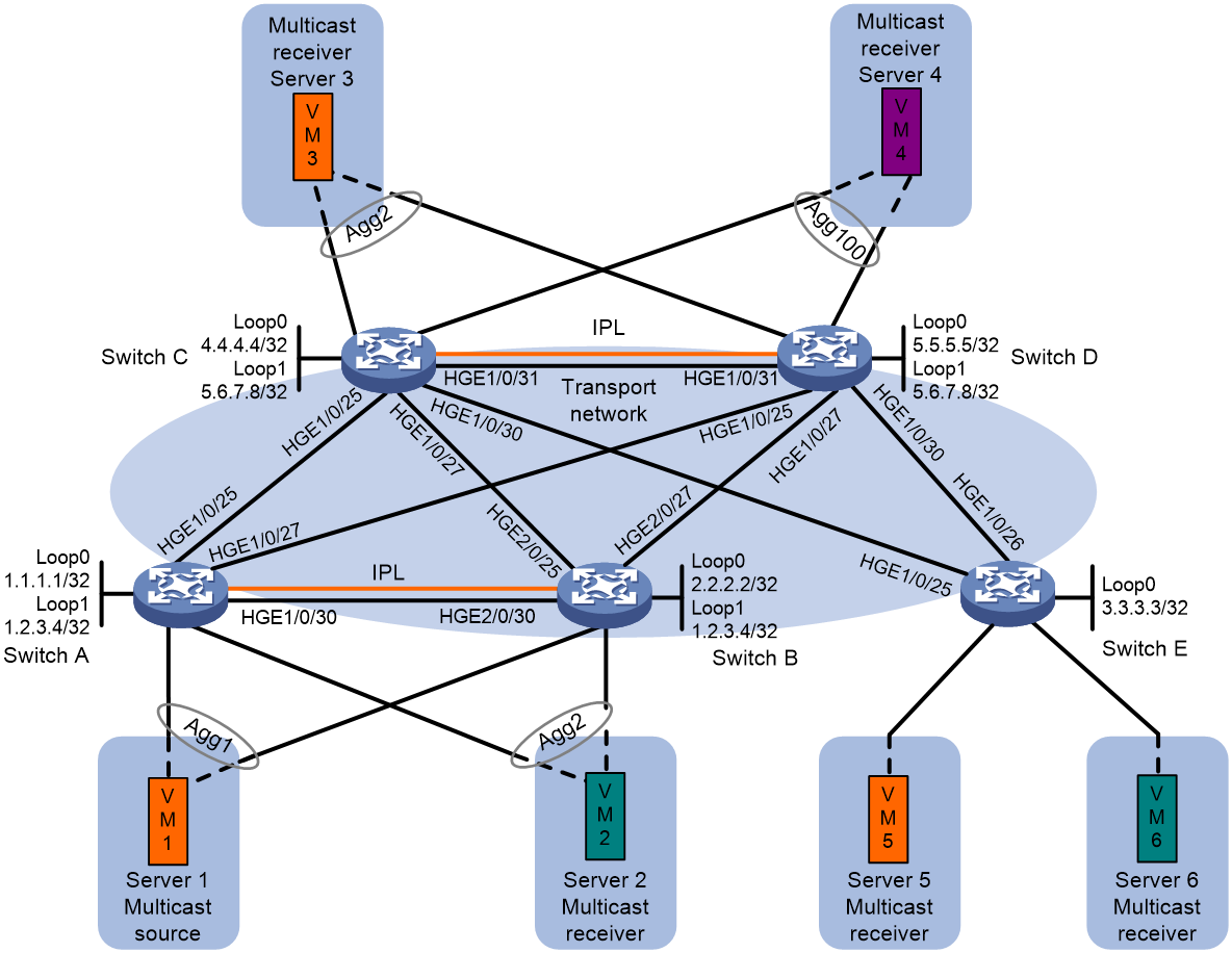
Table 1 Interface and IP address assignment
|
Device |
Interface |
IP address |
|
Switch A |
Loopback 0 |
1.1.1.1/32 |
|
Loopback 1 |
1.2.3.4/32 |
|
|
Loopback 2 |
1.2.3.4/32 |
|
|
HundredGigE 1/0/25 |
11.1.1.2/24 |
|
|
HundredGigE 1/0/27 |
12.1.1.2/24 |
|
|
HundredGigE 1/0/30 |
21.0.0.1/24 |
|
|
VSI-interface 1 |
10.1.1.1/24 |
|
|
VSI-interface 2 |
10.1.2.1/24 |
|
|
Switch B |
Loopback 0 |
2.2.2.2/32 |
|
Loopback 1 |
1.2.3.4/32 |
|
|
Loopback 2 |
1.2.3.4/32 |
|
|
HundredGigE 2/0/25 |
13.1.1.2/24 |
|
|
HundredGigE 2/0/27 |
14.1.1.2/24 |
|
|
HundredGigE 2/0/30 |
21.0.0.2/24 |
|
|
VSI-interface 1 |
10.1.1.1/24 |
|
|
VSI-interface 2 |
10.1.2.1/24 |
|
|
Switch C |
Loopback 0 |
4.4.4.4/32 |
|
Loopback 1 |
5.6.7.8/32 |
|
|
Loopback 2 |
5.6.7.8/32 |
|
|
HundredGigE 1/0/25 |
11.1.1.1/24 |
|
|
HundredGigE 1/0/27 |
13.1.1.1/24 |
|
|
HundredGigE 1/0/30 |
15.1.1.1/24 |
|
|
HundredGigE 1/0/31 |
21.1.0.1 |
|
|
VSI-interface 1 |
10.1.1.1/24 |
|
|
VSI-interface 2 |
10.1.2.1/24 |
|
|
VLAN-interface 100 |
100.1.1.3/24 |
|
|
Switch D |
Loopback 0 |
5.5.5.5/32 |
|
Loopback 1 |
5.6.7.8/32 |
|
|
Loopback 2 |
5.6.7.8/32 |
|
|
HundredGigE 1/0/25 |
12.1.1.1/24 |
|
|
HundredGigE 1/0/27 |
14.1.1.1/24 |
|
|
HundredGigE 1/0/30 |
16.1.1.1/24 |
|
|
HundredGigE 1/0/31 |
21.1.0.2 |
|
|
VSI-interface 1 |
10.1.1.1/24 |
|
|
VSI-interface 2 |
10.1.2.1/24 |
|
|
VLAN-interface 100 |
100.1.1.4/24 |
|
|
Switch E |
Loopback 0 |
3.3.3.3/32 |
|
Loopback 1 |
3.3.3.3/32 |
|
|
HundredGigE 1/0/25 |
15.1.1.2/24 |
|
|
HundredGigE 1/0/26 |
16.1.1.2/24 |
|
|
VSI-interface 1 |
10.1.1.1/24 |
|
|
VSI-interface 2 |
10.1.2.1/24 |
Applicable product matrix
|
|
IMPORTANT: In addition to running an applicable software version, you must also install the most recent patch, if any. |
|
Device |
Software version |
|
S6805, S6825, S6850, and S9850 |
F6632 and higher F66xx or R66xx versions |
|
S12500G-AF |
R7624P12 |
|
S6800 and S6860 |
No versions recommended |
|
S12500X-AF, S6890, S9820-64H, and S9820-8C |
Not supported |
|
S6812 and S6813 |
To be released. To obtain the availability of software, contact H3C Technical Support. |
Restrictions and guidelines
· The member devices in a DR system must use the same DR system MAC address. Different DR systems must each have a unique DR system MAC address on the network.
· As a best practice, run a dynamic routing protocol between the spine devices and the external network. If you use static routing, rebooting spine devices might cause traffic interruption. For example, traffic interruption occurs if the service modules that provide IPP member ports, keepalive interfaces, and DR interfaces start up slower than other service modules. To resolve the issue, use one of the following solutions:
¡ Assign ports operating at the same rate to the IPPs on all service modules to ensure that the IPPs are always restored first. If the member ports cannot operate at the same rate, use the link-aggregation ignore speed command on the IPPs to ensure ports at all rates can be selected. In this solution, hash congestion or uneven load sharing might occur.
¡ On the spine devices, configure a monitor link group. To ensure that the uplink interfaces always start up earlier than the downlink DR interfaces, assign all downlink DR member ports to the monitor link group as uplink interfaces and assign all uplink interfaces to the monitor link group as downlink interfaces. The maintainability of this solution is weak. When you add, delete, or modify DR groups, you must update the uplink interfaces of the monitor link group accordingly.
· All ACs must be dual-homed to the DR member devices. Singlehomed ACs are not supported. Multicast traffic load sharing is not supported. The IPL can only be an Ethernet aggregate link.
· MVXLAN supports only IPv4 underlay networks and IPv4 overlay networks in the current software version.
· As a best practice, create frame match criteria based on VXLAN IDs for the dynamic ACs on the IPL.
· As a best practice to ensure correct traffic forwarding, do not allow IPP s or DR interfaces to forward traffic in the VLANs to which transport-facing interfaces are assigned.
· When a device plays all roles of leaf, border, and spine, packet loss occurs if the multicast source is on the public network and the receivers are attached to ACs in VPN instances. If such multicast traffic exists, do not configure a device to play all roles of leaf, border, and spine.
Configuring access devices
Procedure summary
· Configuring access devices Switch A and Switch B
· Configuring access device Switch E
Configuring access devices Switch A and Switch B
|
Switch A |
Switch B |
Description |
|
ip vpn-instance vpn1 |
ip vpn-instance vpn1 |
Create VPN instance vpn1. |
|
route-distinguisher 1:1 |
route-distinguisher 1:1 |
Configure an RD for the VPN instance. |
|
address-family ipv4 |
address-family ipv4 |
Enter VPN instance IPv4 address family view. |
|
vpn-target 2:2 |
vpn-target 2:2 |
Configure a route target for the VPN instance. |
|
quit |
quit |
N/A |
|
address-family evpn |
address-family evpn |
Enter VPN instance EVPN view. |
|
vpn-target 1:1 |
vpn-target 1:1 |
Configure a route target for EVPN. |
|
quit |
quit |
N/A |
|
quit |
quit |
N/A |
|
ospf 1 router-id 1.1.1.1 |
ospf 1 router-id 2.2.2.2 |
Enable OSPF process 1, specify a route ID, and enter OSPF process view. |
|
stub-router include-stub on-startup 900 |
stub-router include-stub on-startup 900 |
Configure the router as a stub router during reboot and specify the timeout time to 900 seconds. |
|
area 0.0.0.0 |
area 0.0.0.0 |
Create an OSPF area. |
|
quit |
quit |
N/A |
|
quit |
quit |
N/A |
|
interface loopback 0 |
interface loopback 0 |
Create interface Loopback 0. |
|
pim sm |
pim sm |
Enable PIM SM on the interface. |
|
ospf 1 area 0.0.0.0 |
ospf 1 area 0.0.0.0 |
Enable OSPF process 1 on the interface. |
|
quit |
quit |
N/A |
|
interface loopback 1 |
interface loopback 1 |
Create interface Loopback 1. |
|
pim sm |
pim sm |
Enable PIM SM on the interface. |
|
ospf 1 area 0.0.0.0 |
ospf 1 area 0.0.0.0 |
Enable OSPF process 1 on the interface. |
|
quit |
quit |
N/A |
|
interface loopback 2 |
interface loopback 2 |
Create interface Loopback 2. |
|
ip binding vpn-instance vpn1 |
ip binding vpn-instance vpn1 |
Associate the interface with VPN instance vpn1. |
|
pim sm |
pim sm |
Enable PIM SM on the interface. |
|
interface hundredgige 1/0/25 |
interface hundredgige 2/0/25 |
Enter interface view. |
|
pim sm |
pim sm |
Enable PIM SM on the interface. |
|
ospf 1 area 0.0.0.0 |
ospf 1 area 0.0.0.0 |
Enable OSPF process 1 on the interface. |
|
quit |
quit |
N/A |
|
interface hundredgige 1/0/27 |
interface hundredgige 2/0/27 |
Enter interface view. |
|
pim sm |
pim sm |
Enable PIM SM on the interface. |
|
ospf 1 area 0.0.0.0 |
ospf 1 area 0.0.0.0 |
Enable OSPF process 1 on the interface. |
|
quit |
quit |
N/A |
|
interface hundredgige 1/0/30 |
interface hundredgige 2/0/30 |
Enter interface view. |
|
ospf 1 area 0.0.0.0 |
ospf 1 area 0.0.0.0 |
Enable OSPF process 1 on the interface. |
|
quit |
quit |
N/A |
|
l2vpn enable |
l2vpn enable |
Enable L2VPN. |
|
vxlan tunnel mac-learning disable |
vxlan tunnel mac-learning disable |
Disable remote MAC learning. |
|
vxlan tunnel arp-learning disable |
vxlan tunnel arp-learning disable |
Disable remote ARP learning. |
|
evpn global-mac 0001-0002-0003 |
evpn global-mac 0001-0002-0003 |
Specify a global EVPN MAC address. |
|
vsi vpn1 |
vsi vpn1 |
Create VSI vpn1 and enter VSI view. |
|
flooding disable unknown-unicast unknown-multicast |
flooding disable unknown-unicast unknown-multicast |
Disable flooding for the VSI. |
|
vxlan 10 |
vxlan 10 |
Create VXLAN 10 and enter VXLAN view. |
|
quit |
quit |
N/A |
|
evpn encapsulation vxlan |
evpn encapsulation vxlan |
Create an EVPN instance. |
|
route-distinguisher auto |
route-distinguisher auto |
Configure the switch to automatically generate an RD for the EVPN instance. |
|
vpn-target auto |
vpn-target auto |
Configure the switch to automatically generate a route target for the EVPN instance. |
|
quit |
quit |
N/A |
|
quit |
quit |
N/A |
|
vsi vpn2 |
vsi vpn2 |
Create VSI vpn2 and enter VSI view. |
|
flooding disable unknown-unicast unknown-multicast |
flooding disable unknown-unicast unknown-multicast |
Disable flooding for the VSI. |
|
vxlan 20 |
vxlan 20 |
Create VXLAN 20 and enter VXLAN view. |
|
quit |
quit |
N/A |
|
evpn encapsulation vxlan |
evpn encapsulation vxlan |
Create an EVPN instance. |
|
route-distinguisher auto |
route-distinguisher auto |
Configure the switch to automatically generate an RD for the EVPN instance. |
|
vpn-target auto |
vpn-target auto |
Configure the switch to automatically generate a route target for the EVPN instance. |
|
quit |
quit |
N/A |
|
quit |
quit |
N/A |
|
interface vsi-interface 1 |
interface vsi-interface 1 |
Create VSI-interface 1. |
|
ip binding vpn-instance vpn1 |
ip binding vpn-instance vpn1 |
Associate the VSI interface with VPN instance vpn1. |
|
mac-address 0001-0001-0001 |
mac-address 0001-0001-0001 |
Specify a MAC address for the VSI interface. |
|
local-proxy-arp enable |
local-proxy-arp enable |
Enable local proxy ARP. |
|
distributed-gateway local |
distributed-gateway local |
Specify the VSI interface as a distributed gateway. |
|
pim distributed-dr |
pim distributed-dr |
Configure the VSI interface as a distributed designated router interface. |
|
igmp enable |
igmp enable |
Enable IGMP on the interface. |
|
pim sm |
pim sm |
Enable PIM SM on the interface. |
|
quit |
quit |
N/A |
|
interface vsi-interface 2 |
interface vsi-interface 2 |
Create VSI-interface 2. |
|
ip binding vpn-instance vpn1 |
ip binding vpn-instance vpn1 |
Associate the VSI interface with VPN instance vpn1. |
|
mac-address 0002-0002-0002 |
mac-address 0002-0002-0002 |
Specify a MAC address for the VSI interface. |
|
local-proxy-arp enable |
local-proxy-arp enable |
Enable local proxy ARP. |
|
distributed-gateway local |
distributed-gateway local |
Specify the VSI interface as a distributed gateway. |
|
pim distributed-dr |
pim distributed-dr |
Configure the VSI interface as a distributed designated router interface. |
|
igmp enable |
igmp enable |
Enable IGMP on the interface. |
|
pim sm |
pim sm |
Enable PIM SM on the interface. |
|
quit |
quit |
N/A |
|
interface vsi-interface 3 |
interface vsi-interface 3 |
Create VSI-interface 3. |
|
ip binding vpn-instance vpn1 |
ip binding vpn-instance vpn1 |
Associate the VSI interface with VPN instance vpn1. |
|
pim sm |
pim sm |
Enable PIM SM on the interface. |
|
l3-vni 1000 |
l3-vni 1000 |
Configure the Layer 3 VXLAN ID as 1000. |
|
quit |
quit |
N/A |
|
vsi vpn1 |
vsi vpn1 |
Enter the view of VSI vpn1. |
|
gateway vsi-interface 1 |
gateway vsi-interface 1 |
Specify VSI-interface 1 as the gateway interface for the VSI. |
|
quit |
quit |
N/A |
|
vsi vpn2 |
vsi vpn2 |
Enter the view of VSI vpn2. |
|
gateway vsi-interface 2 |
gateway vsi-interface 2 |
Specify VSI-interface 2 as the gateway interface for the VSI. |
|
quit |
quit |
N/A |
|
l2vpn drni peer-link ac-match-rule vxlan-mapping |
l2vpn drni peer-link ac-match-rule vxlan-mapping |
Enable the switch to create frame match criteria based on VXLAN IDs for the dynamic ACs on the IPL. |
|
evpn drni group 1.2.3.4 |
evpn drni group 1.2.3.4 |
Enable EVPN distributed relay and specify the virtual VTEP address. |
|
evpn drni local 1.1.1.1 remote 2.2.2.2 |
evpn drni local 2.2.2.2 remote 1.1.1.1 |
Specify the IP addresses of the local and peer VTEPs in the DR system. |
|
drni restore-delay 300 |
drni restore-delay 300 |
Set the data restoration interval to 300 seconds. |
|
drni system-mac 0021-0021-0021 |
drni system-mac 0021-0021-0021 |
Configure the DR system MAC address. |
|
drni system-number 1 |
drni system-number 2 |
Set the DR system number. |
|
drni system-priority 21 |
drni system-priority 21 |
Set the DR system priority. |
|
drni standalone enable |
drni standalone enable |
Enable DRNI standalone mode. |
|
drni keepalive ip destination 21.0.0.2 source 21.0.0.1 |
drni keepalive ip destination 21.0.0.1 source 21.0.0.2 |
Configure DR keepalive packet parameters. |
|
interface bridge-aggregation 1 |
interface bridge-aggregation 1 |
Create Layer 2 aggregate interface Bridge-Aggregation 1 and enter its view. |
|
link-aggregation mode dynamic |
link-aggregation mode dynamic |
Configure the aggregation group to operate in dynamic aggregation mode and enable LACP. |
|
quit |
quit |
N/A |
|
interface hundredgige 1/0/29 |
interface hundredgige 2/0/29 |
Enter interface view. |
|
port link-aggregation group 1 |
port link-aggregation group 1 |
Assign the interface to aggregation group 1. |
|
quit |
quit |
N/A |
|
interface bridge-aggregation 1 |
interface bridge-aggregation 1 |
Enter the view of Bridge-Aggregation 1. |
|
port drni intra-portal-port 1 |
port drni intra-portal-port 1 |
Configure Bridge-Aggregation 1 as the IPP. |
|
undo mac-address static source-check enable |
undo mac-address static source-check enable |
Disable static source check to ensure correct Layer 3 forwarding over the IPL. |
|
quit |
quit |
N/A |
|
interface bridge-aggregation 2 |
interface bridge-aggregation 2 |
Create Layer 2 aggregate interface Bridge-Aggregation 2 and enter its view. |
|
link-aggregation mode dynamic |
link-aggregation mode dynamic |
Configure the aggregation group to operate in dynamic aggregation mode and enable LACP. |
|
port trunk pvid vlan 4040 |
port trunk pvid vlan 4040 |
Configure the Layer 2 aggregate interface as a trunk port and set its PVID to 4040. |
|
quit |
quit |
N/A |
|
interface hundredgige 1/0/26 |
interface hundredgige 2/0/26 |
Enter interface view. |
|
port link-aggregation group 2 |
port link-aggregation group 2 |
Assign the interface to aggregation group 2. |
|
quit |
quit |
N/A |
|
interface bridge-aggregation 2 |
interface bridge-aggregation 2 |
Enter the view of Bridge-Aggregation 2. |
|
port link-type trunk |
port link-type trunk |
Set the link type of the aggregate interface to trunk. |
|
undo port trunk permit vlan 1 |
undo port trunk permit vlan 1 |
Remove the aggregate interface from VLAN 1. |
|
port trunk permit vlan 2 to 3 |
port trunk permit vlan 2 to 3 |
Assign the aggregate interface to VLANs 2 and 3. |
|
port drni group 2 |
port drni group 2 |
Assign the aggregate interface to DR group 2. |
|
quit |
quit |
N/A |
|
drni mad exclude interface hundredgige 1/0/25 |
drni mad exclude interface hundredgige 2/0/25 |
Exclude an interface from the DRNI MAD shutdown action. |
|
drni mad exclude interface hundredgige 1/0/27 |
drni mad exclude interface hundredgige 2/0/27 |
Exclude an interface from the DRNI MAD shutdown action. |
|
drni mad exclude interface hundredgige 1/0/30 |
drni mad exclude interface hundredgige 2/0/30 |
Exclude an interface from the DRNI MAD shutdown action. |
|
drni mad exclude interface loopback 0 |
drni mad exclude interface loopback 0 |
Exclude an interface from the DRNI MAD shutdown action. |
|
drni mad exclude interface loopback 1 |
drni mad exclude interface loopback 1 |
Exclude an interface from the DRNI MAD shutdown action. |
|
drni mad exclude interface loopback 2 |
drni mad exclude interface loopback 2 |
Exclude an interface from the DRNI MAD shutdown action. |
|
drni mad exclude interface vsi-interface 1 |
drni mad exclude interface vsi-interface 1 |
Exclude an interface from the DRNI MAD shutdown action. |
|
drni mad exclude interface vsi-interface 2 |
drni mad exclude interface vsi-interface 2 |
Exclude an interface from the DRNI MAD shutdown action. |
|
drni mad exclude interface vsi-interface 3 |
drni mad exclude interface vsi-interface 3 |
Exclude an interface from the DRNI MAD shutdown action. |
|
bgp 100 |
bgp 100 |
Create BGP instance 100. |
|
router-id 1.1.1.1 |
router-id 2.2.2.2 |
Configure a router ID for the BGP instance. |
|
peer 4.4.4.4 as-number 100 |
peer 4.4.4.4 as-number 100 |
Specify an AS number for a peer group. |
|
peer 4.4.4.4 connect-interface loopback 0 |
peer 4.4.4.4 connect-interface loopback 0 |
Specify a source interface for establishing TCP connections to a peer or peer group. |
|
peer 5.5.5.5 as-number 100 |
peer 5.5.5.5 as-number 100 |
Specify an AS number for a peer group. |
|
peer 5.5.5.5 connect-interface loopback 0 |
peer 5.5.5.5 connect-interface loopback 0 |
Specify a source interface for establishing TCP connections to a peer or peer group. |
|
address-family l2vpn evpn |
address-family l2vpn evpn |
Enter BGP EVPN address family view. |
|
peer 4.4.4.4 enable |
peer 4.4.4.4 enable |
Enable BGP to exchange unicast routing information with a peer or peer group. |
|
peer 5.5.5.5 enable |
peer 5.5.5.5 enable |
Enable BGP to exchange unicast routing information with a peer or peer group. |
|
quit |
quit |
N/A |
|
quit |
quit |
N/A |
|
interface bridge-aggregation 2 |
interface bridge-aggregation 2 |
Enter the view of Bridge-Aggregation 2. |
|
service-instance 1000 |
service-instance 1000 |
Create Ethernet service instance 1000. |
|
encapsulation s-vid 2 |
encapsulation s-vid 2 |
Configure a frame match criterion for the Ethernet service instance. |
|
xconnect vsi vpn1 |
xconnect vsi vpn1 |
Map VSI vpn1 to the Ethernet service instance. |
|
service-instance 1001 |
service-instance 1001 |
Create Ethernet service instance 1001. |
|
encapsulation s-vid 3 |
encapsulation s-vid 3 |
Configure a frame match criterion for the Ethernet service instance. |
|
xconnect vsi vpn2 |
xconnect vsi vpn2 |
Map VSI vpn2 to the Ethernet service instance. |
|
quit |
quit |
N/A |
|
quit |
quit |
N/A |
|
igmp-snooping |
igmp-snooping |
Enable IGMP snooping on the switch and enter IGMP-snooping view. |
|
quit |
quit |
N/A |
|
vsi vpn1 |
vsi vpn1 |
Enter the view of VSI vpn1. |
|
igmp-snooping enable |
igmp-snooping enable |
Enable IGMP snooping for the VSI. |
|
pim-snooping enable |
pim-snooping enable |
Enable PIM snooping for the VSI. |
|
igmp-snooping proxy enable |
igmp-snooping proxy enable |
Enable IGMP snooping proxying for the VSI. |
|
quit |
quit |
N/A |
|
vsi vpn2 |
vsi vpn2 |
Enter the view of VSI vpn2. |
|
igmp-snooping enable |
igmp-snooping enable |
Enable IGMP snooping for the VSI. |
|
pim-snooping enable |
pim-snooping enable |
Enable PIM snooping for the VSI. |
|
igmp-snooping proxy enable |
igmp-snooping proxy enable |
Enable IGMP snooping proxying for the VSI. |
|
quit |
quit |
N/A |
|
multicast-vpn vxlan vpn-instance vpn1 mode mdt |
multicast-vpn vxlan vpn-instance vpn1 mode mdt |
Create an MDT-based MVXLAN. |
|
address-family ipv4 |
address-family ipv4 |
Enter MVXLAN IPv4 address family view. |
|
source loopback 1 evpn-drni-group |
source loopback 1 evpn-drni-group |
Specify the virtual VTEP address of the DR member devices as the IP address of the source interface. |
|
default-group 239.0.0.1 |
default-group 239.0.0.1 |
Configure the default group. |
|
data-group 239.0.1.0 255.255.255.128 |
data-group 239.0.1.0 255.255.255.128 |
Configure the data group range. |
|
drni local 1.1.1.1 remote 2.2.2.2 |
drni local 2.2.2.2 remote 1.1.1.1 |
Specify the IP addresses of the local and remote DR member devices. |
|
quit |
quit |
N/A |
|
quit |
quit |
N/A |
|
multicast routing |
multicast routing |
Enable IP multicast routing for the public network. |
|
quit |
quit |
N/A |
|
multicast routing vpn-instance vpn1 |
multicast routing vpn-instance vpn1 |
Enable IP multicast routing for VPN instance vpn1. |
|
quit |
quit |
N/A |
|
pim |
pim |
Enable PIM for the public network. |
|
c-bsr 1.1.1.1 |
c-bsr 2.2.2.2 |
Configure a candidate-BSR. |
|
c-rp 1.1.1.1 |
c-rp 2.2.2.2 |
Configure a candidate-RP. |
|
quit |
quit |
N/A |
|
pim vpn-instance vpn1 |
pim vpn-instance vpn1 |
Enable PIM for VPN instance vpn1. |
|
c-bsr 1.2.3.4 |
c-bsr 1.2.3.4 |
Configure a candidate-BSR. |
|
c-rp 1.2.3.4 |
c-rp 1.2.3.4 |
Configure a candidate-RP. |
Configuring access device Switch E
Configure Switch E in the same way Switch A and Switch B are configured except that DRNI settings are not required on Switch E. For more information about interface and IP address assignment on Switch E, see Table 1. For more information about the configuration procedure, see "Configuring access devices Switch A and Switch B."
|
Switch E |
Description |
|
multicast-vpn vxlan vpn-instance vpn1 mode mdt |
Create an MDT-based MVXLAN. |
|
address-family ipv4 |
Enter MVXLAN IPv4 address family view. |
|
source loopback 0 |
Specify Loopback 0 as the source interface. |
|
default-group 239.0.0.1 |
Configure the default group. |
|
data-group 239.0.1.0 255.255.255.128 |
Configure the data group range. |
|
quit |
N/A |
|
quit |
N/A |
|
multicast routing |
Enable IP multicast routing for the public network. |
|
quit |
N/A |
|
multicast routing vpn-instance vpn1 |
Enable IP multicast routing for VPN instance vpn1. |
|
quit |
N/A |
|
pim |
Enable PIM for the public network. |
|
c-bsr 3.3.3.3 |
Configure a candidate-BSR. |
|
c-rp 3.3.3.3 |
Configure a candidate-RP. |
|
quit |
N/A |
|
pim vpn-instance vpn1 |
Enable PIM for VPN instance vpn1. |
|
c-bsr 3.3.3.3 |
Configure a candidate-BSR. |
|
c-rp 3.3.3.3 |
Configure a candidate-RP. |
Configuring core devices
|
Switch C |
Switch D |
Description |
|
ip vpn-instance external_vpn |
ip vpn-instance external_vpn |
Create VPN instance external_vpn. |
|
route-distinguisher 1:100 |
route-distinguisher 1:100 |
Configure an RD for the VPN instance. |
|
address-family ipv4 |
address-family ipv4 |
Enter VPN instance IPv4 address family view. |
|
vpn-target 100:100 2:2 |
vpn-target 100:100 2:2 |
Configure route targets for the VPN instance. |
|
quit |
quit |
N/A |
|
quit |
quit |
N/A |
|
ip vpn-instance vpn1 |
ip vpn-instance vpn1 |
Create VPN instance vpn1. |
|
route-distinguisher 1:1 |
route-distinguisher 1:1 |
Configure an RD for the VPN instance. |
|
address-family ipv4 |
address-family ipv4 |
Enter VPN instance IPv4 address family view. |
|
vpn-target 2:2 1:2 |
vpn-target 2:2 1:2 |
Configure route targets for the VPN instance. |
|
address-family evpn |
address-family evpn |
Enter VPN instance EVPN view. |
|
vpn-target 1:1 |
vpn-target 1:1 |
Configure a route target for EVPN. |
|
quit |
quit |
N/A |
|
quit |
quit |
N/A |
|
ospf 1 router-id 4.4.4.4 |
ospf 1 router-id 5.5.5.5 |
Enable OSPF process 1 and specify a router ID for the process. |
|
stub-router include-stub on-startup 900 |
stub-router include-stub on-startup 900 |
Configure the router as a stub router during reboot and specify the timeout time to 900 seconds. |
|
area 0.0.0.0 |
area 0.0.0.0 |
Create an OSPF area. |
|
quit |
quit |
N/A |
|
quit |
quit |
N/A |
|
ospf 2 vpn-instance external_vpn |
ospf 2 vpn-instance external_vpn |
Enable OSPF process 2 and specify VPN instance external_vpn for the process. |
|
stub-router include-stub on-startup 900 |
stub-router include-stub on-startup 900 |
Configure the router as a stub router during reboot and specify the timeout time to 900 seconds. |
|
area 0.0.0.0 |
area 0.0.0.0 |
Create an OSPF area. |
|
quit |
quit |
N/A |
|
quit |
quit |
N/A |
|
interface hundredgige 1/0/25 |
interface hundredgige 1/0/25 |
Enter interface view. |
|
pim sm |
pim sm |
Enable PIM SM on the interface. |
|
ospf 1 area 0.0.0.0 |
ospf 1 area 0.0.0.0 |
Enable OSPF process 1 on the interface. |
|
quit |
quit |
N/A |
|
interface hundredgige 1/0/27 |
interface hundredgige 1/0/27 |
Enter interface view. |
|
pim sm |
pim sm |
Enable PIM SM on the interface. |
|
ospf 1 area 0.0.0.0 |
ospf 1 area 0.0.0.0 |
Enable OSPF process 1 on the interface. |
|
quit |
quit |
N/A |
|
interface hundredgige 1/0/30 |
interface hundredgige 1/0/30 |
Enter interface view. |
|
pim sm |
pim sm |
Enable PIM SM on the interface. |
|
ospf 1 area 0.0.0.0 |
ospf 1 area 0.0.0.0 |
Enable OSPF process 1 on the interface. |
|
quit |
quit |
N/A |
|
interface loopback 0 |
interface loopback 0 |
Create Loopback 0 and enter loopback interface view. |
|
pim sm |
pim sm |
Enable PIM SM on the interface. |
|
ospf 1 area 0.0.0.0 |
ospf 1 area 0.0.0.0 |
Enable OSPF process 1 on the interface. |
|
quit |
quit |
N/A |
|
interface loopback 1 |
interface loopback 1 |
Create Loopback 1 and enter loopback interface view. |
|
pim sm |
pim sm |
Enable PIM SM on the interface. |
|
ospf 1 area 0.0.0.0 |
ospf 1 area 0.0.0.0 |
Enable OSPF process 1 on the interface. |
|
quit |
quit |
N/A |
|
interface loopback 2 |
interface loopback 2 |
Create Loopback 2 and enter loopback interface view. |
|
ip binding vpn-instance vpn1 |
ip binding vpn-instance vpn1 |
Associate the interface with VPN instance vpn1. |
|
pim sm |
pim sm |
Enable PIM SM on the interface. |
|
quit |
quit |
N/A |
|
l2vpn enable |
l2vpn enable |
Enable L2VPN. |
|
vxlan tunnel mac-learning disable |
vxlan tunnel mac-learning disable |
Disable remote-MAC address learning. |
|
vxlan tunnel arp-learning disable |
vxlan tunnel arp-learning disable |
Disable remote ARP learning for VXLANs. |
|
evpn global-mac 0001-0002-0004 |
evpn global-mac 0001-0002-0004 |
Configure the EVPN global MAC address. |
|
vsi vpn1 |
vsi vpn1 |
Create VSI vpn1 and enter VSI view. |
|
flooding disable unknown-unicast unknown-multicast |
flooding disable unknown-unicast unknown-multicast |
Disable flooding for the VSI. |
|
vxlan 10 |
vxlan 10 |
Create VXLAN 10 and enter its view. |
|
quit |
quit |
N/A |
|
evpn encapsulation vxlan |
evpn encapsulation vxlan |
Create an EVPN instance. |
|
route-distinguisher auto |
route-distinguisher auto |
Configure the switch to automatically generate an RD for the EVPN instance. |
|
vpn-target auto |
vpn-target auto |
Configure the switch to automatically generate a route target for the EVPN instance. |
|
quit |
quit |
N/A |
|
quit |
quit |
N/A |
|
vsi vpn2 |
vsi vpn2 |
Create VSI vpn2 and enter VSI view. |
|
flooding disable unknown-unicast unknown-multicast |
flooding disable unknown-unicast unknown-multicast |
Disable flooding for the VSI. |
|
vxlan 20 |
vxlan 20 |
Create VXLAN 20 and enter its view. |
|
quit |
quit |
N/A |
|
evpn encapsulation vxlan |
evpn encapsulation vxlan |
Create an EVPN instance. |
|
route-distinguisher auto |
route-distinguisher auto |
Configure the switch to automatically generate an RD for the EVPN instance. |
|
vpn-target auto |
vpn-target auto |
Configure the switch to automatically generate a route target for the EVPN instance. |
|
quit |
quit |
N/A |
|
quit |
quit |
N/A |
|
interface vsi-interface 1 |
interface vsi-interface 1 |
Create VSI-interface 1. |
|
ip binding vpn-instance vpn1 |
ip binding vpn-instance vpn1 |
Associate the VSI interface with VPN instance vpn1. |
|
mac-address 0001-0001-0001 |
mac-address 0001-0001-0001 |
Configure the MAC address of the VSI interface. |
|
local-proxy-arp enable |
local-proxy-arp enable |
Enable local proxy ARP on the VSI interface. |
|
distributed-gateway local |
distributed-gateway local |
Specify the VSI interface as a distributed gateway. |
|
pim distributed-dr |
pim distributed-dr |
Configure the VSI interface as a distributed designated router interface. |
|
igmp enable |
igmp enable |
Enable IGMP on the VSI interface. |
|
pim sm |
pim sm |
Enable PIM SM on the VSI interface. |
|
quit |
quit |
N/A |
|
interface vsi-interface 2 |
interface vsi-interface 2 |
Create VSI-interface 2. |
|
ip binding vpn-instance vpn1 |
ip binding vpn-instance vpn1 |
Associate the VSI interface with VPN instance vpn1. |
|
mac-address 0002-0002-0002 |
mac-address 0002-0002-0002 |
Configure the MAC address of the VSI interface. |
|
local-proxy-arp enable |
local-proxy-arp enable |
Enable local proxy ARP on the VSI interface. |
|
distributed-gateway local |
distributed-gateway local |
Specify the VSI interface as a distributed gateway. |
|
pim distributed-dr |
pim distributed-dr |
Configure the VSI interface as a distributed designated router interface. |
|
igmp enable |
igmp enable |
Enable IGMP on the VSI interface. |
|
pim sm |
pim sm |
Enable PIM SM on the VSI interface. |
|
quit |
quit |
N/A |
|
interface vsi-interface 3 |
interface vsi-interface 3 |
Create VSI-interface 3. |
|
ip binding vpn-instance vpn1 |
ip binding vpn-instance vpn1 |
Associate the VSI interface with VPN instance vpn1. |
|
pim sm |
pim sm |
Enable PIM SM on the VSI interface. |
|
l3-vni 1000 |
l3-vni 1000 |
Configure the L3 VXLAN ID as 1000 for the VPN instance. |
|
quit |
quit |
N/A |
|
interface vsi-interface 4 |
interface vsi-interface 4 |
Create VSI-interface 4. |
|
ip binding vpn-instance external_vpn |
ip binding vpn-instance external_vpn |
Associate the VSI interface with VPN instance external_vpn. |
|
pim sm |
pim sm |
Enable PIM SM on the VSI interface. |
|
l3-vni 2000 |
l3-vni 2000 |
Configure the L3 VXLAN ID as 2000 for the VPN instance. |
|
quit |
quit |
N/A |
|
vsi vpn1 |
vsi vpn1 |
Enter the view of VSI vpn1. |
|
gateway vsi-interface 1 |
gateway vsi-interface 1 |
Specify VSI-interface 1 as the gateway interface for the VSI. |
|
quit |
quit |
N/A |
|
vsi vpn2 |
vsi vpn2 |
Enter the view of VSI vpn2. |
|
gateway vsi-interface 2 |
gateway vsi-interface 2 |
Specify VSI-interface 2 as the gateway interface for the VSI. |
|
quit |
quit |
N/A |
|
l2vpn drni peer-link ac-match-rule vxlan-mapping |
l2vpn drni peer-link ac-match-rule vxlan-mapping |
Enable the switch to create frame match criteria based on VXLAN IDs for the dynamic ACs on the IPL. |
|
evpn drni group 5.6.7.8 |
evpn drni group 5.6.7.8 |
Enable EVPN distributed relay and specify the virtual VTEP address. |
|
evpn drni local 4.4.4.4 remote 5.5.5.5 |
evpn drni local 5.5.5.5 remote 4.4.4.4 |
Specify the IP addresses of the local and peer VTEPs in the DR system. |
|
drni restore-delay 300 |
drni restore-delay 300 |
Set the data restoration interval to 300 seconds. |
|
drni system-mac 0022-0022-0022 |
drni system-mac 0022-0022-0022 |
Configure the DR system MAC address. |
|
drni system-number 1 |
drni system-number 2 |
Set the DR system number. |
|
drni system-priority 22 |
drni system-priority 22 |
Set the DR system priority. |
|
drni standalone enable |
drni standalone enable |
Enable DRNI standalone mode. |
|
drni keepalive ip destination 21.1.0.2 source 21.1.0.1 |
drni keepalive ip destination 21.1.0.1 source 21.1.0.2 |
Configure DR keepalive packet parameters. |
|
interface bridge-aggregation 1 |
interface bridge-aggregation 1 |
Create Layer 2 aggregate interface Bridge-Aggregation 1 and enter its view. |
|
link-aggregation mode dynamic |
link-aggregation mode dynamic |
Configure the aggregation group to operate in dynamic aggregation mode and enable LACP. |
|
quit |
quit |
N/A |
|
interface hundredgige 1/0/32 |
interface hundredgige 1/0/32 |
Enter interface view. |
|
port link-aggregation group 1 |
port link-aggregation group 1 |
Assign the interface to aggregation group 1. |
|
quit |
quit |
N/A |
|
interface bridge-aggregation 1 |
interface bridge-aggregation 1 |
Enter the view of Bridge-Aggregation 1. |
|
port drni intra-portal-port 1 |
port drni intra-portal-port 1 |
Configure the aggregate interface as the IPP. |
|
port trunk pvid vlan 4050 |
port trunk pvid vlan 4050 |
Configure the aggregate interface as a trunk port and set its PVID to 4050. |
|
undo mac-address static source-check enable |
undo mac-address static source-check enable |
Disable static source check to ensure correct Layer 3 forwarding over the IPL. |
|
quit |
quit |
N/A |
|
interface bridge-aggregation 2 |
interface bridge-aggregation 2 |
Create Layer 2 aggregate interface Bridge-Aggregation 2 and enter its view. |
|
link-aggregation mode dynamic |
link-aggregation mode dynamic |
Configure the aggregation group to operate in dynamic aggregation mode and enable LACP. |
|
quit |
quit |
N/A |
|
interface hundredgige 1/0/26 |
interface hundredgige 1/0/26 |
Enter interface view. |
|
port link-aggregation group 2 |
port link-aggregation group 2 |
Assign the interface to aggregation group 2. |
|
quit |
quit |
N/A |
|
vlan 2 to 3 100 |
vlan 2 to 3 100 |
Create VLANs 2, 3, and 100. |
|
quit |
quit |
N/A |
|
interface bridge-aggregation 2 |
interface bridge-aggregation 2 |
Enter the view of Bridge-Aggregation 2. |
|
port link-type trunk |
port link-type trunk |
Set the link type of the aggregate interface to trunk. |
|
undo port trunk permit vlan 1 |
undo port trunk permit vlan 1 |
Remove the aggregate interface from VLAN 1. |
|
port trunk permit vlan 2 to 3 |
port trunk permit vlan 2 to 3 |
Assign the aggregate interface to VLANs 2 and 3. |
|
port drni group 2 |
port drni group 2 |
Assign the aggregate interface to DR group 2. |
|
service-instance 1000 |
service-instance 1000 |
Create Ethernet service instance 1000. |
|
encapsulation s-vid 2 |
encapsulation s-vid 2 |
Configure a frame match criterion for the Ethernet service instance. |
|
xconnect vsi vpn1 |
xconnect vsi vpn1 |
Map the Ethernet service instance to VSI vpn1. |
|
service-instance 1001 |
service-instance 1001 |
Create Ethernet service instance 1001. |
|
encapsulation s-vid 3 |
encapsulation s-vid 3 |
Configure a frame match criterion for the Ethernet service instance. |
|
xconnect vsi vpn2 |
xconnect vsi vpn2 |
Map the Ethernet service instance to VSI vpn2. |
|
quit |
quit |
N/A |
|
quit |
quit |
N/A |
|
interface bridge-aggregation 100 |
interface bridge-aggregation 100 |
Create Layer 2 aggregate interface Bridge-Aggregation 100 and enter its view. |
|
link-aggregation mode dynamic |
link-aggregation mode dynamic |
Configure the aggregation group to operate in dynamic aggregation mode and enable LACP. |
|
quit |
quit |
N/A |
|
interface hundredgige 1/0/29 |
interface hundredgige 1/0/29 |
Enter interface view. |
|
port link-aggregation group 100 |
port link-aggregation group 100 |
Assign the interface to aggregation group 100. |
|
quit |
quit |
N/A |
|
interface bridge-aggregation 100 |
interface bridge-aggregation 100 |
Enter the view of Bridge-Aggregation 100. |
|
port link-type trunk |
port link-type trunk |
Set the link type of the aggregate interface to trunk. |
|
undo port trunk permit vlan 1 |
undo port trunk permit vlan 1 |
Remove the aggregate interface from VLAN 1. |
|
port trunk permit vlan 100 |
port trunk permit vlan 100 |
Assign the aggregate interface to VLAN 100. |
|
port drni group 100 |
port drni group 100 |
Assign the aggregate interface to DR group 100. |
|
quit |
quit |
N/A |
|
interface hundredgige 1/0/31 |
interface hundredgige 1/0/31 |
Enter interface view. |
|
ospf 1 area 0.0.0.0 |
ospf 1 area 0.0.0.0 |
Enable OSPF process 1 on the interface. |
|
pim sm |
pim sm |
Enable PIM SM on the interface. |
|
quit |
quit |
N/A |
|
drni mad exclude interface hundredgige 1/0/25 |
drni mad exclude interface hundredgige 1/0/25 |
Exclude an interface from the DRNI MAD shutdown action. |
|
drni mad exclude interface hundredgige 1/0/27 |
drni mad exclude interface hundredgige 1/0/27 |
Exclude an interface from the DRNI MAD shutdown action. |
|
drni mad exclude interface hundredgige 1/0/28 |
drni mad exclude interface hundredgige 1/0/28 |
Exclude an interface from the DRNI MAD shutdown action. |
|
drni mad exclude interface hundredgige 1/0/31 |
drni mad exclude interface hundredgige 1/0/31 |
Exclude an interface from the DRNI MAD shutdown action. |
|
drni mad exclude interface loopback 0 |
drink mad exclude interface loopback 0 |
Exclude an interface from the DRNI MAD shutdown action. |
|
drni mad exclude interface vlan-interface 100 |
drni mad exclude interface vlan-interface 100 |
Exclude an interface from the DRNI MAD shutdown action. |
|
drni mad exclude interface vsi-interface 1 |
drni mad exclude interface vsi-interface 1 |
Exclude an interface from the DRNI MAD shutdown action. |
|
drni mad exclude interface vsi-interface 2 |
drni mad exclude interface vsi-interface 2 |
Exclude an interface from the DRNI MAD shutdown action. |
|
drni mad exclude interface vsi-interface 3 |
drni mad exclude interface vsi-interface 3 |
Exclude an interface from the DRNI MAD shutdown action. |
|
drni mad exclude interface vsi-interface 4 |
drni mad exclude interface vsi-interface 4 |
Exclude an interface from the DRNI MAD shutdown action. |
|
bgp 100 |
bgp 100 |
Create BGP instance 100. |
|
router-id 4.4.4.4 |
router-id 5.5.5.5 |
Configure a router ID for the BGP instance. |
|
group e internal |
group e internal |
Create a peer group. |
|
peer e connect-interface loopback 0 |
peer e connect-interface loopback 0 |
Specify a source interface for establishing TCP connections to a peer or peer group. |
|
peer 1.1.1.1 group e |
peer 1.1.1.1 group e |
Add peer 1.1.1.1 to the peer group. |
|
peer 2.2.2.2 group e |
peer 2.2.2.2 group e |
Add peer 2.2.2.2 to the peer group. |
|
peer 3.3.3.3 group e |
peer 3.3.3.3 group e |
Add peer 3.3.3.3 to the peer group. |
|
address-family l2vpn evpn |
address-family l2vpn evpn |
Enter BGP EVPN address family view. |
|
undo policy vpn-target |
undo policy vpn-target |
Disable route target filtering for BGP EVPN routes. |
|
peer e enable |
peer e enable |
Enable BGP to exchange unicast routing information with a peer or peer group. |
|
peer e next-hop-local |
peer e next-hop-local |
Set the local router as the next hop for routes sent to a peer or peer group. |
|
peer e reflect-client |
peer e reflect-client |
Configure the local switch as a route reflector and specify peer group e as a client. |
|
quit |
quit |
N/A |
|
quit |
quit |
N/A |
|
igmp-snooping |
igmp-snooping |
Enable IGMP snooping and enter IGMP-snooping view. |
|
quit |
quit |
N/A |
|
vlan 100 |
vlan 100 |
Create VLAN 100. |
|
igmp-snooping enable |
igmp-snooping enable |
Enable IGMP snooping for the VLAN. |
|
pim-snooping enable |
pim-snooping enable |
Enable PIM snooping for the VLAN. |
|
igmp-snooping triggered-query enable port-down port-up |
igmp-snooping triggered-query enable port-down port-up |
Enable the switch to send IGMP general queries when the state of a port changes. |
|
quit |
quit |
N/A |
|
interface vlan-interface 100 |
interface vlan-interface 100 |
Create VLAN-interface 100. |
|
ip binding vpn-instance external_vpn |
ip binding vpn-instance external_vpn |
Associate the VLAN interface with VPN instance external_vpn. |
|
pim sm |
pim sm |
Enable PIM SM. |
|
pim distributed-dr |
pim distributed-dr |
Configure the VLAN interface as a distributed designated router interface. |
|
pim triggered-hello enable port-down port-up |
pim triggered-hello enable port-down port-up |
Enable the switch to send hello messages with a different Generation ID when the state of a port changes. |
|
igmp enable |
igmp enable |
Enable IGMP on the interface. |
|
quit |
quit |
N/A |
|
multicast-vpn vxlan vpn-instance external_vpn mode mdt |
multicast-vpn vxlan vpn-instance external_vpn mode mdt |
Create an MDT-based MVXLAN and enter MVXLAN view. |
|
address-family ipv4 |
address-family ipv4 |
Enter MVXLAN IPv4 address family view. |
|
source loopback 1 evpn-drni-group |
source loopback 1 evpn-drni-group |
Specify the virtual VTEP address of the DR member devices as the IP address of the source interface. |
|
default-group 239.0.2.0 |
default-group 239.0.2.0 |
Configure the default group. |
|
data-group 239.0.3.0 255.255.255.128 |
data-group 239.0.3.0 255.255.255.128 |
Configure the data group range. |
|
drni local 4.4.4.4 remote 5.5.5.5 |
drni local 5.5.5.5 remote 4.4.4.4 |
Specify the IP addresses of the local and remote DR member devices. |
|
quit |
quit |
N/A |
|
quit |
quit |
N/A |
|
multicast-vpn vxlan vpn-instance vpn1 mode mdt |
multicast-vpn vxlan vpn-instance vpn1 mode mdt |
Create an MDT-based MVXLAN and enter MVXLAN view. |
|
address-family ipv4 |
address-family ipv4 |
Enter MVXLAN IPv4 address family view. |
|
source loopback 1 evpn-drni-group |
source loopback 1 evpn-drni-group |
Specify the virtual VTEP address of the DR member devices as the IP address of the source interface. |
|
default-group 239.0.0.1 |
default-group 239.0.0.1 |
Configure the default group. |
|
data-group 239.0.1.0 255.255.255.128 |
data-group 239.0.1.0 255.255.255.128 |
Configure the data group range. |
|
drni local 4.4.4.4 remote 5.5.5.5 |
drni local 5.5.5.5 remote 4.4.4.4 |
Specify the IP addresses of the local and remote DR member devices. |
|
quit |
quit |
N/A |
|
quit |
quit |
N/A |
|
multicast routing |
multicast routing |
Enable IP multicast routing for the public network. |
|
quit |
quit |
N/A |
|
multicast routing vpn-instance external_vpn |
multicast routing vpn-instance external_vpn |
Enable IP multicast routing for VPN instance external_vpn. |
|
multicast extranet select-rpf l3-vni 1000 group 226.0.0.0 8 |
multicast extranet select-rpf l3-vni 1000 group 226.0.0.0 8 |
Configure an IPv4 MVXLAN extranet RPF selection policy. |
|
quit |
quit |
N/A |
|
multicast routing vpn-instance vpn1 |
multicast routing vpn-instance vpn1 |
Enable IP multicast routing for VPN instance vpn1. |
|
quit |
quit |
N/A |
|
pim |
pim |
Enable PIM for the public network. |
|
c-bsr 4.4.4.4 |
c-bsr 5.5.5.5 |
Configure a candidate-BSR. |
|
c-rp 4.4.4.4 |
c-rp 5.5.5.5 |
Configure a candidate-RP. |
|
quit |
quit |
N/A |
|
pim vpn-instance external_vpn |
pim vpn-instance external_vpn |
Enable PIM for VPN instance external_vpn. |
|
c-bsr 4.4.4.4 |
c-bsr 5.5.5.5 |
Configure a candidate-BSR. |
|
c-rp 4.4.4.4 |
c-rp 5.5.5.5 |
Configure a candidate-RP. |
|
quit |
quit |
N/A |
|
quit |
quit |
N/A |
|
pim vpn-instance vpn1 |
pim vpn-instance vpn1 |
Enable PIM for VPN instance vpn1. |
|
c-bsr 5.6.7.8 |
c-bsr 5.6.7.8 |
Configure a candidate-BSR. |
|
c-rp 5.6.7.8 |
c-rp 5.6.7.8 |
Configure a candidate-RP. |
Overlay traffic forwarding models
Overlay traffic characteristics
The following table describes overlay traffic characteristics:
|
Parameter |
Description |
|
No. |
Overlay traffic number in the format of O-4-xxx or O-6-xxx. O represents overlay, 4 represents IPv4, 6 represents IPv6, and xxx represents the traffic number starting from 001. |
|
Traffic type |
Traffic type, which is IPv4 multicast. |
|
Direction |
Traffic direction. Traffic can be forwarded from leaf to border, east to north across leaf devices, and from border to leaf. |
|
Forwarding path |
List of nodes that the traffic passes through. |
|
Traffic simulation |
Simulation method used in the test. A tester is simulated as a server to transmit traffic. |
|
Load |
Traffic load is light or heavy. If the number of flows is less than 1000, the load is light. If the number of flows is more than 1000, the load is heavy. |
|
Traffic direction to firewalls/LB |
Enter the method used to direct traffic to firewalls or LBs. In this example, no firewalls or LBs are deployed. |
Forwarding models
|
No. |
Traffic type |
Direction |
Forwarding path |
Traffic simulation |
Load |
Traffic direction to firewalls/LB |
|
O-4-001 |
IPv4 multicast |
East to west, across leaf devices |
Server 1 > Switch A&Switch B > Switch E > Server 5 |
Bond4+ tester |
Light |
N/A |
|
O-4-002 |
IPv4 multicast |
Leaf to border |
Server 1 > Switch A&Switch B > Switch C&Switch D > Server 4 |
Bond4+ tester |
Light |
N/A |
Testing network convergence
|
Device |
Failure type |
Traffic interruption time |
Recovery type |
Traffic interruption time |
|
Leaf |
Single point of failure for ECMP uplinks |
≤ 500 ms |
Recovery from single point of failure for ECMP uplinks |
0 ms |
|
Single point of failure for DR member links |
≤ 500 ms |
Recovery from single point of failure for DR member links |
≤ 150 ms |
|
|
IPL failure |
≤ 3000 ms |
IPL failure recovery |
≤ 4000 ms |
|
|
Keepalive link failure |
0 ms |
Recovery from keepalive link failure |
0 ms |
|
|
Keepalive link and IPL failure |
≤ 5000 ms |
Recovery from keepalive link and IPL failure |
≤ 8000 ms |
|
|
Upgrading a device |
≤ 3000 ms |
|
|
|
|
Expanding the network |
0 ms |
|
|
|
|
Replacing hardware |
≤ 3000 ms |
|
|
|
|
Border |
Single point of failure for ECMP uplinks |
≤ 500 ms |
Recovery from single point of failure for ECMP uplinks |
0 ms |
|
Single point of failure for DR member links |
≤ 500 ms |
Recovery from single point of failure for DR member links |
≤ 150 ms |
|
|
IPL failure |
≤ 3000 ms |
IPL failure recovery |
≤ 4000 ms |
|
|
Keepalive link failure |
0 ms |
Recovery from keepalive link failure |
0 ms |
|
|
Keepalive link and IPL failure |
Second level for traffic forwarding recovery |
Recovery from keepalive link and IPL failure |
Second level for traffic switchover |
|
|
Upgrading a device |
≤ 3000 ms |
|
|
|
|
Expanding the network |
0 ms |
|
|
|
|
Replacing hardware |
≤ 3000 ms |
|
|
Verifying the configuration
Verification commands
|
Switch D |
Switch E |
Description |
|
display multicast-vpn vxlan { vpn-instance instance-name | public-instance } data-group receive [ brief | [ active | group group-address | sender source-address | vpn-source-address [ mask { mask-length | mask } ] | vpn-group-address [ mask { mask-length | mask } ] ] * ] |
display multicast-vpn vxlan { vpn-instance instance-name | public-instance } data-group receive [ brief | [ active | group group-address | sender source-address | vpn-source-address [ mask { mask-length | mask } ] | vpn-group-address [ mask { mask-length | mask } ] ] * ] |
Displays received data group information in an MVXLAN. |
|
display multicast-vpn vxlan { vpn-instance instance-name | public-instance } data-group send [ group group-address | vpn-source-address [ mask { mask-length | mask } ] | vpn-group-address [ mask { mask-length | mask } ] ] * |
display multicast-vpn vxlan { vpn-instance instance-name | public-instance } data-group send [ group group-address | vpn-source-address [ mask { mask-length | mask } ] | vpn-group-address [ mask { mask-length | mask } ] ] * |
Displays sent data group information in an MVXLAN. |
|
display multicast-vpn vxlan [ vpn-instance instance-name | public-instance ] default-group { local | remote } |
display multicast-vpn vxlan [ vpn-instance instance-name | public-instance ] default-group { local | remote } |
Displays information about default groups. |
Procedure
The following information uses Switch A as an example.
# Display EVPN SMET routes.
<SwitchA> display bgp l2vpn evpn route-type smet
BGP local router ID is 1.1.1.1
Status codes: * - valid, > - best, d - dampened, h - history
s - suppressed, S - stale, i - internal, e - external
a - additional-path
Origin: i - IGP, e - EGP, ? - incomplete
Total number of routes from all PEs: 3200
Route distinguisher: 1:1(vpn1)
Total number of routes: 2600
Network NextHop MED LocPrf PrefVal Path/Ogn
* >i [6][0][0][0.0.0.0][32][225.0.0.1][32][4.4.4.4]/128
4.4.4.4 0 100 0
Path/Ogn: i
* >i [6][0][0][0.0.0.0][32][225.0.0.1][32][5.5.5.5]/128
5.5.5.5 0 100 0
Path/Ogn: i
* >i [6][0][0][0.0.0.0][32][225.0.0.2][32][4.4.4.4]/128
4.4.4.4 0 100 0
Path/Ogn: i
# Display S-PMSI routes.
<SwitchA> display bgp l2vpn evpn route-type s-pmsi
BGP local router ID is 1.1.1.1
Status codes: * - valid, > - best, d - dampened, h - history
s - suppressed, S - stale, i - internal, e - external
a - additional-path
Origin: i - IGP, e - EGP, ? - incomplete
Total number of routes from all PEs: 1010
Route distinguisher: 1:1(vpn1)
Total number of routes: 1507
Network NextHop MED LocPrf PrefVal Path/Ogn
* > [10][0][0][0.0.0.0][0][0.0.0.0][32][1.1.1.1]/96
0.0.0.0 0 100 32768
Path/Ogn: i
* >i [10][0][0][0.0.0.0][0][0.0.0.0][32][2.2.2.2]/96
2.2.2.2 0 100 0
Path/Ogn: i
* i 2.2.2.2 0 100 0
Path/Ogn: i
* >i [10][0][0][0.0.0.0][0][0.0.0.0][32][3.3.3.3]/96
3.3.3.3 0 100 0
Path/Ogn: i
* i 3.3.3.3 0 100 0
Path/Ogn: i
* >i [10][0][0][0.0.0.0][0][0.0.0.0][32][4.4.4.4]/96
4.4.4.4 0 100 0
Path/Ogn: i
* >i [10][0][0][0.0.0.0][0][0.0.0.0][32][5.5.5.5]/96
5.5.5.5 0 100 0
# Display VXLAN tunnel information.
<SwitchA> display interface tunnel
Tunnel0
Current state: UP
Line protocol state: UP
Description: Tunnel0 Interface
Bandwidth: 64 kbps
Maximum transmission unit: 1464
Internet protocol processing: Disabled
Last clearing of counters: Never
Tunnel source 1.2.3.4, destination 4.4.4.4
Tunnel protocol/transport UDP_VXLAN/IP
Last 300 seconds input rate: 0 bytes/sec, 0 bits/sec, 0 packets/sec
Last 300 seconds output rate: 0 bytes/sec, 0 bits/sec, 0 packets/sec
Input: 0 packets, 0 bytes, 0 drops
Output: 0 packets, 0 bytes, 0 drops
Tunnel1
Current state: UP
Line protocol state: UP
Description: Tunnel1 Interface
Bandwidth: 64 kbps
Maximum transmission unit: 1464
Internet protocol processing: Disabled
Last clearing of counters: Never
Tunnel source 1.2.3.4, destination 5.6.7.8
Tunnel protocol/transport UDP_VXLAN/IP
Last 300 seconds input rate: 0 bytes/sec, 0 bits/sec, 0 packets/sec
Last 300 seconds output rate: 0 bytes/sec, 0 bits/sec, 0 packets/sec
Input: 0 packets, 0 bytes, 0 drops
Output: 0 packets, 0 bytes, 0 drops
Tunnel2
Current state: UP
Line protocol state: UP
Description: Tunnel2 Interface
Bandwidth: 64 kbps
Maximum transmission unit: 1464
Internet protocol processing: Disabled
Last clearing of counters: Never
Tunnel source 1.2.3.4, destination 5.5.5.5
Tunnel protocol/transport UDP_VXLAN/IP
Last 300 seconds input rate: 0 bytes/sec, 0 bits/sec, 0 packets/sec
Last 300 seconds output rate: 0 bytes/sec, 0 bits/sec, 0 packets/sec
Input: 0 packets, 0 bytes, 0 drops
Output: 0 packets, 0 bytes, 0 drops
Tunnel3
Current state: UP
Line protocol state: UP
Description: Tunnel3 Interface
Bandwidth: 64 kbps
Maximum transmission unit: 1464
Internet protocol processing: Disabled
Last clearing of counters: Never
Tunnel source 1.2.3.4, destination 3.3.3.3
Tunnel protocol/transport UDP_VXLAN/IP
Last 300 seconds input rate: 0 bytes/sec, 0 bits/sec, 0 packets/sec
Last 300 seconds output rate: 0 bytes/sec, 0 bits/sec, 0 packets/sec
Input: 0 packets, 0 bytes, 0 drops
Output: 0 packets, 0 bytes, 0 drops
# Display brief information about multicast tunnel interfaces.
<SwitchA> display interface mtunnel brief
Brief information on interfaces in route mode:
Link: ADM - administratively down; Stby - standby
Protocol: (s) - spoofing
Interface Link Protocol Primary IP Description
MTunnel0 UP UP 1.2.3.4
MTunnel1 UP UP 1.2.3.4
MTunnel2 UP UP 1.2.3.4
MTunnel3 UP UP 1.2.3.4
...
# Display PIM routing entries in VPN instance vpna.
<SwitchA> display pim vpn-instance vpna routing-table
Total 1 (*, G) entries; 1 (S, G) entries
(*, 225.0.0.0)
RP: 12.12.12.12 (local)
Protocol: pim-sm, Flag: WC RC
UpTime: 03:01:20
Upstream interface: Register-Tunnel0
Upstream neighbor: NULL
RPF prime neighbor: NULL
Downstream interface information:
Total number of downstream interfaces: 1
1: MTunnel0
Protocol: MD, UpTime: 02:57:31, Expires: -
2: Vsi-interface2
Protocol: igmp, UpTime: 03:01:22, Expires: -
(10.1.1.10, 225.0.0.0)
RP: 12.12.12.12 (local)
Protocol: pim-sm, Flag: SPT 2MSDP LOC ACT SQ RC 2MVPN
UpTime: 03:01:20
Upstream interface: Vsi-interface1
Upstream neighbor: NULL
RPF prime neighbor: NULL
Downstream interface information:
Total number of downstream interfaces: 1
1: MTunnel1
Protocol: MD, UpTime: 02:56:31, Expires: -
2: Vsi-interface2
Protocol: igmp, UpTime: 03:01:22, Expires: -
# Display the DR system settings.
[SwitchA] display drni system
IPP: BAGG1
State: UP
DR System number System MAC System priority
Local 1 0001-0001-0001 123
Peer 2 0001-0001-0001 123
# Display summary information about the IPP and DR interfaces.
[SwitchA] display drni summary
Global consistency check : SUCCESS
Inconsistent type 1 global settings: -
IPP IPP ID State
BAGG1 1 UP
DR interface DR group ID State Check result Type 1 inconsistency
BAGG1 1 UP SUCCESS -
BAGG1 2 UP SUCCESS -
Upgrading the devices
Upgrading a leaf device
Checking the environment
Execute the commands in "Verification commands" and the following commands to verify that the device is available for an upgrade.
|
Leaf 1 |
Leaf 2 |
Description |
|
display device |
display device |
Displays device information. |
|
display boot-loader |
display boot-loader |
Displays current software images and startup software images. |
|
display version |
display version |
Displays system version information. |
Upgrading the device
See H3C Switches DR System Upgrade & Replacement & Expansion Guide.
Verifying the traffic interruption time during the upgrade
Verify that the traffic interruption time is shorter than 500 ms during a switchover and shorter than 150 ms during fallback. For more information, see "Testing network convergence."
Verifying the upgrade result
Execute the commands in "Verification commands" and the following commands to verify that the device is upgraded successfully.
|
Leaf 1 |
Leaf 2 |
Description |
|
display device |
display device |
Displays device information. |
|
display boot-loader |
display boot-loader |
Displays current software images and startup software images. |
|
display version |
display version |
Displays system version information. |
Upgrading a spine device
Checking the environment
Execute the commands in "Verification commands" and the following commands to verify that the device is available for an upgrade.
|
Spine 1 |
Spine 2 |
Description |
|
display device |
display device |
Displays device information. |
|
display boot-loader |
display boot-loader |
Displays current software images and startup software images. |
|
display version |
display version |
Displays system version information. |
Upgrading the device
1. Use the display version command to verify the current BootWare image version and startup software version.
2. Use the release notes for the upgrade software version to evaluate the upgrade impact on your network and verify the following items:
¡ Software and hardware compatibility.
¡ Version and size of the upgrade software.
¡ Compatibility of the upgrade software with the current BootWare image and startup software image.
3. Use the release notes to verify whether the software images require a license. If licenses are required, register and activate licenses for each license-based software image.
4. Use the dir command to verify that the device has sufficient storage space for the upgrade images. If the storage space is not sufficient, delete unused files by using the delete command.
5. Use FTP or TFTP to transfer the upgrade image file to the root directory of a file system.
6. Upgrade the device according to the configuration guides for the device.
Verifying the traffic interruption time during the upgrade
Verify that the traffic interruption time is shorter than 500 ms during a switchover and shorter than 150 ms during fallback. For more information, see "Testing network convergence."
Verifying the upgrade result
Execute the commands in "Verification commands" and the following commands to verify that the device is upgraded successfully.
|
Leaf 1 |
Leaf 2 |
Description |
|
display device |
display device |
Displays device information. |
|
display boot-loader |
display boot-loader |
Displays current software images and startup software images. |
|
display version |
display version |
Displays system version information. |
Upgrading a border device
Checking the environment
Execute the commands in "Verification commands" and the following commands to verify that the device is available for an upgrade.
|
Border 1 |
Border 2 |
Description |
|
display device |
display device |
Displays device information. |
|
display boot-loader |
display boot-loader |
Displays current software images and startup software images. |
|
display version |
display version |
Displays system version information. |
Upgrading the device
See H3C Switches DR System Upgrade & Replacement & Expansion Guide.
Verifying the traffic interruption time during the upgrade
Verify that the traffic interruption time is shorter than 500 ms during a switchover and shorter than 150 ms during fallback. For more information, see "Testing network convergence."
Verifying the upgrade result
Execute the commands in "Verification commands" and the following commands to verify that the device is upgraded successfully.
|
Border 1 |
Border 2 |
Description |
|
display device |
display device |
Displays device information. |
|
display boot-loader |
display boot-loader |
Displays current software images and startup software images. |
|
display version |
display version |
Displays system version information. |
Expanding the network
An expansion operation adds two leaf devices.
Adding a leaf device
Checking the environment
Execute the commands in "Verification commands" and the following commands to verify that the device is available for an expansion.
|
Leaf 1 |
Leaf 2 |
Description |
|
display device |
display device |
Displays device information. |
|
display boot-loader |
display boot-loader |
Displays current software images and startup software images. |
|
display version |
display version |
Displays system version information. |
Adding the device to the leaf tier
1. Disconnect the device from network management systems.
2. Upgrade the software of the device as needed.
3. Preconfigure the device.
4. Connect the device to network management systems.
5. Incorporate the device on the controller.
Verifying the traffic interruption time
For more information, see "Testing network convergence."
Verifying the expansion result
Execute the following commands to verify that the device is added successfully.
|
Leaf 1 |
Leaf 2 |
Description |
|
display device |
display device |
Displays device information. |
|
display boot-loader |
display boot-loader |
Displays current software images and startup software images. |
|
display version |
display version |
Displays system version information. |
Replacing hardware
Replacing a device
Checking the environment
Execute the commands in "Verification commands" and the following commands to verify that the target device is available for a replacement.
|
Leaf 1 |
Leaf 2 |
Description |
|
display device |
display device |
Displays device information. |
|
display boot-loader |
display boot-loader |
Displays current software images and startup software images. |
|
display version |
display version |
Displays system version information. |
Replacing the device
See H3C Switches DR System Upgrade & Replacement & Expansion Guide.
Verifying the traffic interruption time
For more information, see "Testing network convergence."
Verifying the replacement result
Execute the commands in "Checking the environment."