- Table of Contents
-
- H3C SR8800-F Router Series Installation Guide-5W104
- 00-Preface
- 01-Chapter 1 Preparing for Installation
- 02-Chapter 2 Installing the Router
- 03-Chapter 3 Installing FRUs
- 04-Chapter 4 Connecting Your Router to the Network
- 05-Chapter 5 Troubleshooting
- 06-Chapter 6 Replacement Procedures
- 07-Appendix A Chassis Views and Technical Specifications
- 08-Appendix B FRUs and Compatibility Matrixes
- 09-Appendix C LEDs
- 10-Appendix D Slot arrangement and port numbering
- 11-Appendix E Cables
- 12-Appendix F Cable Management
- 13-Appendix G Engineering Labels for Cables
- Related Documents
-
| Title | Size | Download |
|---|---|---|
| 06-Chapter 6 Replacement Procedures | 3.46 MB |
Contents
Replacing the power supply system
Replacing a power supply adapter
Replacing a transceiver module
Replacing an XFP/QSFP+/SFP+/SFP/QSFP28 transceiver module
Replacing a CFP transceiver module
Replacement procedures
|
|
WARNING! · When replacing a field replaceable unit (FRU) on an operating router, be aware of electrical safety hazards. · To avoid bodily injury and device damage, strictly follow the replacement procedure in this section when you replace a component. |
|
|
CAUTION: As a best practice to avoid data theft, remove all data from an FRU that has a storage medium, for example, a CF card, hard disk, or flash before disposal of that FRU. To remove data, format or destroy the storage medium on the FRU. |
The router uses modular design. You can replace FRUs when the router is operating.
Replacing the power supply system
Replacing a power supply adapter
1. Prepare an antistatic mat to place the removed power supply adapter.
2. Wear an ESD wrist strap and make sure it makes good skin contact and is reliably grounded. For more information, see "Attaching an ESD wrist strap."
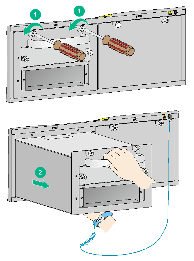
3. Use a Phillips screwdriver to loosen the captive screws on the power supply adapter.
4. Holding the power supply adapter handle with one hand, pull it part way out of the slot. Supporting the adapter bottom with the other, pull it slowly out of the slot.
5. Place the power supply adapter on the antistatic mat.
6. Install a new power supply adapter in the slot. For the installation procedure, see "Installing a power supply adapter."
Figure 1 Removing a power supply adapter
Replacing a power supply
Replacement precautions
Before you replace a power supply, read the following precautions carefully:
· To avoid device damage and bodily injury, strictly follow the procedures shown in Figure 2 and Figure 3 to remove and install a power supply, respectively.
Figure 2 Power supply removal flow
![]()
Figure 3 Power supply installation flow
![]()
· Do not install AC and DC power supplies on the same router. The power supplies on a router must be the same model.
· To avoid device damage, power off the router before replacing two power supplies on the router with a different model.
· For a router using two power supplies, make sure each power supply has a separate circuit breaker. Before replacing a power supply, turn off the circuit breaker for the power supply.
Replacement conditions
Replace a power supply when any of the following conditions exists:
· The power supply is faulty.
· The power output of the current power supplies cannot meet the power requirements of the router.
The system power consumption equals the total dynamic power consumption of all cards plus the maximum power consumption of fans. For more information, see "Module power consumption and total power consumption."
Replacement procedure
1. Prepare an antistatic mat to place the removed power supply.
2. Wear an ESD wrist strap and make sure it has a good skin contact and is reliably grounded. For more information, see "Attaching an ESD wrist strap."
3. Switch off the power supply.
4. Remove the power cord from the power supply.
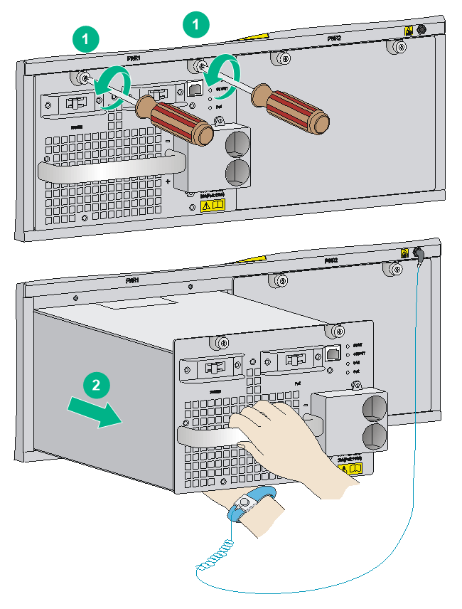
5. Use a Phillips screwdriver to loosen the captive screws on the power supply, as shown by callout 1 in Figure 4.
6. Remove the power supply, as shown by callout 2 in Figure 4:
a. Hold the power supply handle with one hand and support the bottom of the power supply with the other.
b. Gently pull the power supply out.
7. Remove the power adapter. The procedures for removing a power adapter are the same as removing a power supply.
Skip this step if no power adapter is used for the power supply.
8. Put the removed power supply on the antistatic mat.
9. Install a new power supply. For the installation procedure, see "Installing a power supply in the chassis."
10. If you are not to install a new power supply, install a filler panel in the slot. Align the screws on the filler panel with the screw holes on the router, and then use a screwdriver to secure the screws on the filler panel.
Figure 4 Removing the power supply
Replacing a card
|
|
CAUTION: Do not remove the active MPU when the router is operating. To remove an active MPU, execute the reboot command to trigger an active/standby MPU switchover and wait until the MPU has entered standby mode. You can execute the display device command or examine the MPU status LED to determine the active/standby mode of an MPU. For the MPU status LED description, see "MPU active/standby status LED." For more information about the reboot and display device commands, see device management commands in H3C SR8800-F Routers Fundamentals Command Reference. |
|
|
CAUTION: To replace an MPU or service module, first remove all its cables. |
The replacement procedure is the same for the cards
To replace a card:
1. Prepare an antistatic mat to place the removed card.
2. Wear an ESD wrist strap and make sure it has a good skin contact and is correctly grounded. For more information, see "Attaching an ESD wrist strap."
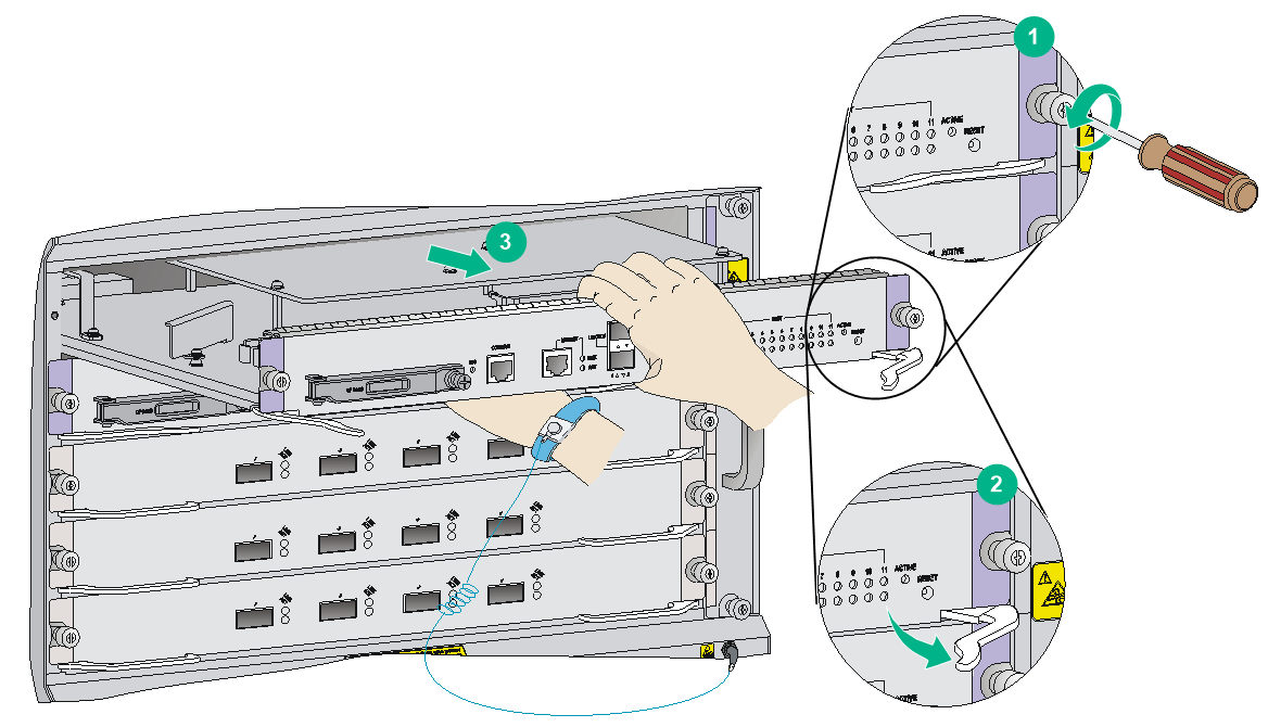
3. Use a Phillips screwdriver to remove the captive screws on the card, as shown by callout 1 in Figure 5.
4. Press the ejector levers down to the horizontal level. (This step applies only to a base card.)
5. Press the ejector levers outward to separate the card from the backplane, as shown by callout 2 in Figure 5.
6. Use one hand to slowly move the card outward. Support the bottom of the card with the other hand while pulling the card out of the slot along slide rails, as shown by callout 3 in Figure 5.
7. Put the removed card on the antistatic mat.
8. Install a new card. For the installation procedures, see "Installing MPUs/service modules."
If no new card is to be installed, install a filler panel to ensure good ventilation and dust proof.
Figure 5 Replacing a card (MPU)
Replacing a subcard
This section describes the procedure for replacing a subcard on a base card. The subcards are hot swappable.
To replace a subcard:
1. Put on an ESD wrist strap, and make sure the wrist strap makes good skin contact and is correctly grounded. For more information, see "Attaching an ESD wrist strap."
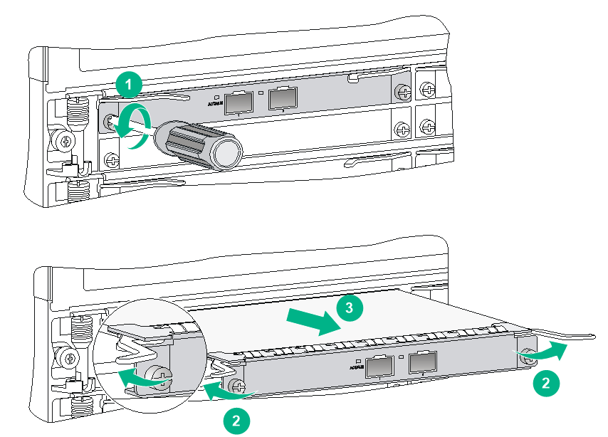
2. Use a Phillips screwdriver to loosen the mounting screws on the subcard, as shown by callout 1 in Figure 6.
3. Press the ejector levers outward to unseat the subcard from the base card, as shown by callout 2 in Figure 6.
4. Slowly pull out the subcard along the guide rails, as shown by callout 3 in Figure 6.
5. Put the removed subcard on an antistatic mat or into the original package.
6. Install a new subcard. For more information about how to install a subcard, see "Installing a subcard."
|
(1) Loosen the mounting screw |
(2) Press the ejector levers outward |
|
(3) Pull the card out |
|
Replacing a fan tray
|
|
WARNING! To avoid bodily injury, do not touch the rotating fans. |
|
|
CAUTION: To ensure correct operation of the router, install a new fan tray within five minutes after the fan tray is removed. |
Removing a fan tray
1. Prepare an antistatic mat or the original package to place the removed fan tray.
2. Wear an ESD wrist strap and make sure it has a good skin contact and is correctly grounded. For more information, see "Attaching an ESD wrist strap."
3. Use a screwdriver to remove the captive screws on the fan tray, as shown by callout 1 in Figure 7.
4. Supporting the fan tray by its bottom with one hand, hold the fan tray handle with the other. Pull the fan tray out of the slot, as shown by callout 2 in Figure 7.
5. Put the removed fan tray on the antistatic mat or into the original package.
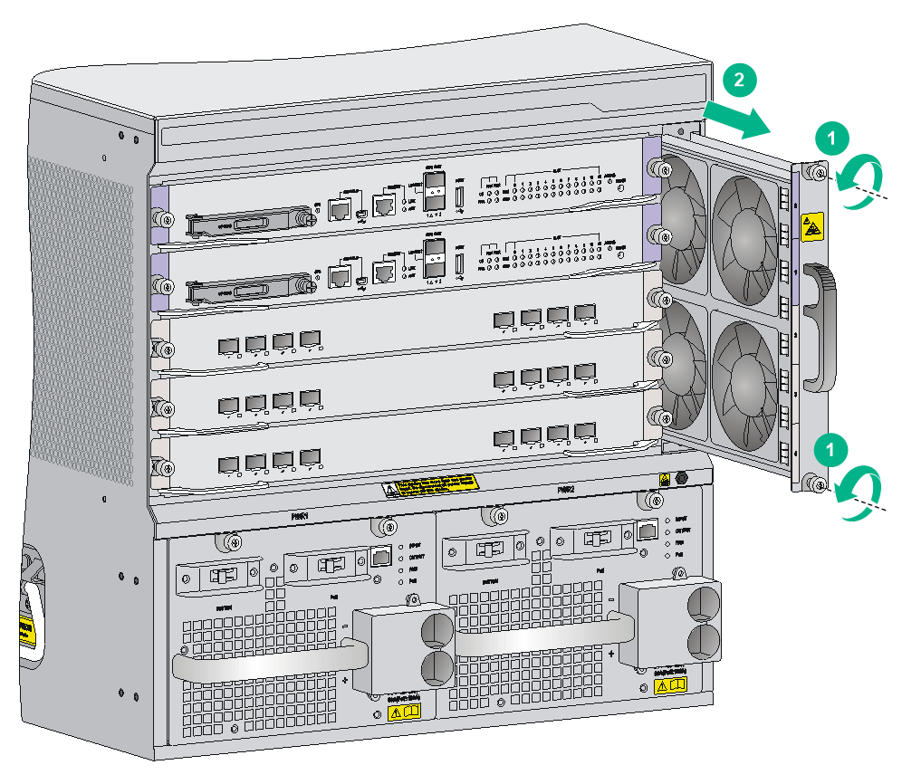
|
(1) Loosen the captive screw |
(2) Press the left side of the fan tray handle to rotate it out from the slot |
|
(3) Pull the fan tray out of the slot |
|
Installing a fan tray
1. Wear an ESD wrist strap and make sure it has a good skin contact and is correctly grounded. For more information, see "Attaching an ESD wrist strap."
2. Unpack a new fan tray.
3. Push the new fan tray into the fan tray slot along the slide rails until it has a close contact with the backplane.
4. Use a screwdriver to fasten the captive screws on the fan tray.
5. Verify that the fan tray is installed correctly by using either of the following methods:
¡ Verify the status of the FAN LEDs on the MPU. If the OK LED is on, the fan tray is installed successfully. For more information about the FAN LEDs, see "Fan tray status LEDs."
¡ Verify the fan status by using the display fan command. For more information, see device management in H3C SR8800-F Routers Fundamentals Command Reference.
Replacing an air filter
|
|
CAUTION: Clean air filters each month to guarantee adequate ventilation and avoid over-temperature. |
To replace an air filter:
1. Use a Phillips screwdriver to loosen the captive screws on the air filter, as shown by callout 1 in Figure 8.
2. Remove the air filter from the chassis, as shown by callout 2 in Figure 8.
3. Install the cleaned air filter to the router.
For more information about how to install an air filter, see "(Optional) Installing an air filter."
Figure 8 Replacing an air filter
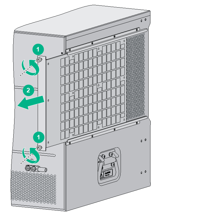
|
(1) Loosen the captive screws on the air filter |
(2) Remove the air filter from the chassis |
Replacing a CF card
|
|
CAUTION: Do not remove the CF card when the router is booting or the CF card LED is flashing. Otherwise, the file system on the hardware or the CF card might be damaged. |
The CF card is installed on the MPU of the router.
To replace a CF card:
1. Verify the CF card LED status.
¡ If the LED is on, you cannot remove the CF card. You must use the umount cfa0: command at the CLI to unmount the CF card and wait until the CF card LED is off. After you execute the umount cf command, if you want to continue to use the CF card, execute the mount cf command in user view to mount the CF card again.
For more information about the umount and mount commands, see file system management in H3C SR8800-F Routers Fundamentals Command Reference.
¡ If the LED is flashing, it means that data is being read from or written to the CF card. In this case, you cannot remove the CF card. Wait until the CF card LED stops flashing.
¡ If the LED is off, it means that the CF card is unmounted, and you can remove the CF card.
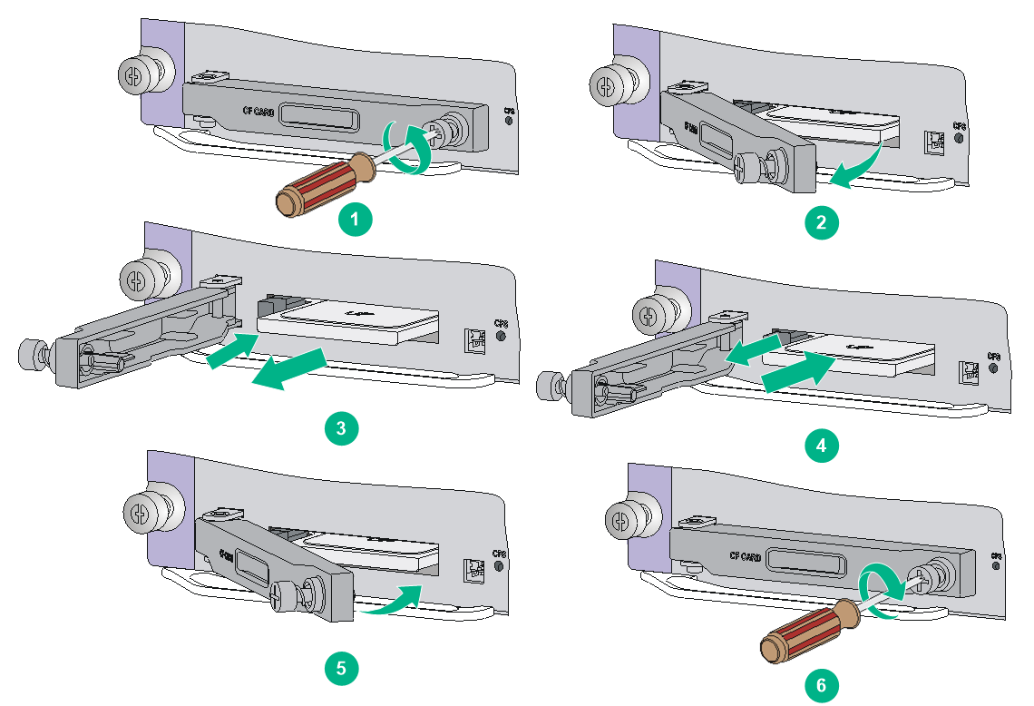
2. Use a Phillips screwdriver to loosen the screw at the right side of the CF card protection cover, and pull the CF card protection cover outward.
Skip this step if the MPU does not have a CF card protection cover.
3. Push the eject button on the CF card slot all the way until the CF card in the slot ejects. Remove the CF card from the slot, and put the removed CF card on an antistatic bag or into its original package.
4. Before inserting the CF card, make sure the CF card eject button is pushed to the end and does not reset automatically. Push the new CF card all the way into the CF card slot until the eject button resets.
5. Push the CF card cover inward and use a Phillips screwdriver to fasten the screw on the CF card protection cover.
Skip this step if the MPU does not have a CF card protection cover.
Figure 9 Replacing a CF card
Replacing a transceiver module
|
|
WARNING! Do not stare into any open apertures of operating transceiver modules or optical fiber connectors. The laser light emitted from these apertures might hurt your eyes. |
|
|
CAUTION: · During the installation or removal process, be careful not to touch the golden plating on the transceiver module. · In case of limited space, you can use the provided tweezers and other tools to remove a transceiver module or optical fiber. |
Make sure the transceiver modules at the two ends of an optical fiber are the same model.
Replacing an XFP/QSFP+/SFP+/SFP/QSFP28 transceiver module
The replacement procedure is similar for XFP, QSFP+, QSFP28, SFP+, and SFP transceiver modules. The following uses an SFP+ transceiver module for illustration.
To replace an SFP+ transceiver module:
1. Wear an ESD wrist strap and make sure it makes good skin contact and is correctly grounded.
For more information, see "Attaching an ESD wrist strap."
2. Remove the optical fibers on the module.
There is a latching mechanism between a fiber connector and transceiver module port to prevent connector disengagement. Release the latching mechanism before removing the optical fiber. To avoid damages, do not use excessive force.
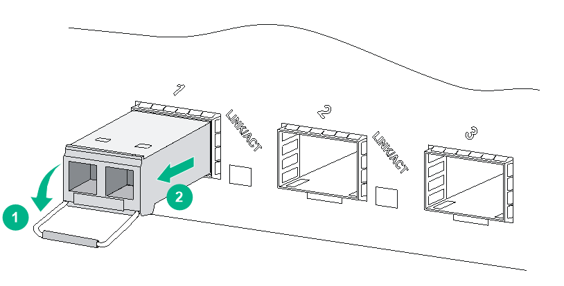
3. Pivot the clasp down to the horizontal position.
4. Grasp the clasp on the module and carefully pull the module out of the slot.
If you use force at an angle, you can hardly pull the transceiver module out and the transceiver module or fiber port might be damaged. If you forcibly pull out of the transceiver module without pivoting the bail latch down, the triangular pin of the transceiver module and the fiber port might be damaged.
To avoid damaging the bail latch, use event force to pull the transceiver module out.
Figure 10 Removing an SFP+ transceiver module
5. Put the dust plug on the removed module, and put the remove module into its original shipping materials.
6. Install a new module.
For the installation procedures, see "Installing an XFP/QSFP+/SFP+/SFP/QSFP28 transceiver module."
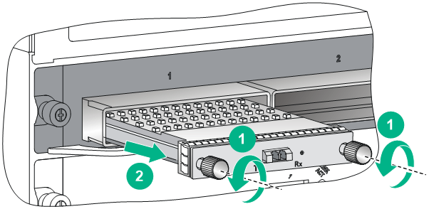
Replacing a CFP transceiver module
1. Wear an ESD wrist strap and make sure it makes good skin contact and is reliably grounded.
For more information, see "Attaching an ESD wrist strap."
2. Remove the optical fibers from the module.
There is a latching mechanism between a fiber connector and transceiver module port to prevent connector disengagement. Release the latching mechanism before removing the optical fiber. To avoid damages, do not use excessive force.
3. Loosen the captive screws on the module.
4. Carefully pull the module out of the port.
If you use force at an angle, you can hardly pull the transceiver module out and the transceiver module or fiber port might be damaged.
Figure 11 Removing the CFP transceiver module
5. Put the dust plug on the removed module, and put the removed module into its original shipping materials.
6. Install a new module. For the installation procedures, see "Installing a CFP transceiver module."
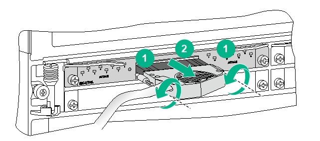
Replacing an E1 cable
1. Wear an ESD wrist strap and make sure it makes good skin contact and is reliably grounded.
For more information, see "Attaching an ESD wrist strap."
2. Use a screwdriver to loosen the screws on the connector of the E1 cable.
3. Pull out the E1 cable slowly.
Figure 12 Removing an E1 cable
4. Install a new E1 cable.
For the installation procedure, see "Connecting an E1 cable."
