- Table of Contents
-
- H3C SR8800-F Router Series Installation Guide-5W104
- 00-Preface
- 01-Chapter 1 Preparing for Installation
- 02-Chapter 2 Installing the Router
- 03-Chapter 3 Installing FRUs
- 04-Chapter 4 Connecting Your Router to the Network
- 05-Chapter 5 Troubleshooting
- 06-Chapter 6 Replacement Procedures
- 07-Appendix A Chassis Views and Technical Specifications
- 08-Appendix B FRUs and Compatibility Matrixes
- 09-Appendix C LEDs
- 10-Appendix D Slot arrangement and port numbering
- 11-Appendix E Cables
- 12-Appendix F Cable Management
- 13-Appendix G Engineering Labels for Cables
- Related Documents
-
| Title | Size | Download |
|---|---|---|
| 04-Chapter 4 Connecting Your Router to the Network | 522.98 KB |
Connecting your router to the network
Accessing the router for the first time
Setting up the configuration environment
Configuring authentication on a user interface
Verifying the network configuration
Connecting the router to the network
Connecting your router to the network through twisted pair cables
Connecting your router to the network through optical fibers
Connecting your router to the network
The first time you access the router, you can only log in to the CLI through the console port or USB console port. After login, you can configure other access methods. The router supports also remote access through Telnet or SSH.
The router provides the following types of user lines:
· Console user line—Manages and monitors users that logs in to the router through the console port.
· AUX user line—Manages and monitors users that logs in to the router through the USB console port.
· Virtual type terminal (VTY) line—Manages and monitors users that logs in to the router through Telnet or SSH.
For more information about login methods and user lines, see login management in H3C SR8800-F Routers Fundamentals Configuration Guide.
Accessing the router for the first time
The first time you access the router you must use a console cable to connect the console port on the router to a configuration terminal, a PC for example. If two MPUs are installed in the router, you can connect the console terminal to the console port on either of the MPUs.
Setting up the configuration environment
|
|
CAUTION: The serial ports on PCs do not support hot swapping. If the router has been powered on, connect the console cable to the PC first and then connect the cable to the router. To disconnect the cable, first disconnect it from the router. |
To connect a terminal (for example, a PC) to the router:
1. Connect the DB-9 female connector of the console cable to the serial port of the PC.
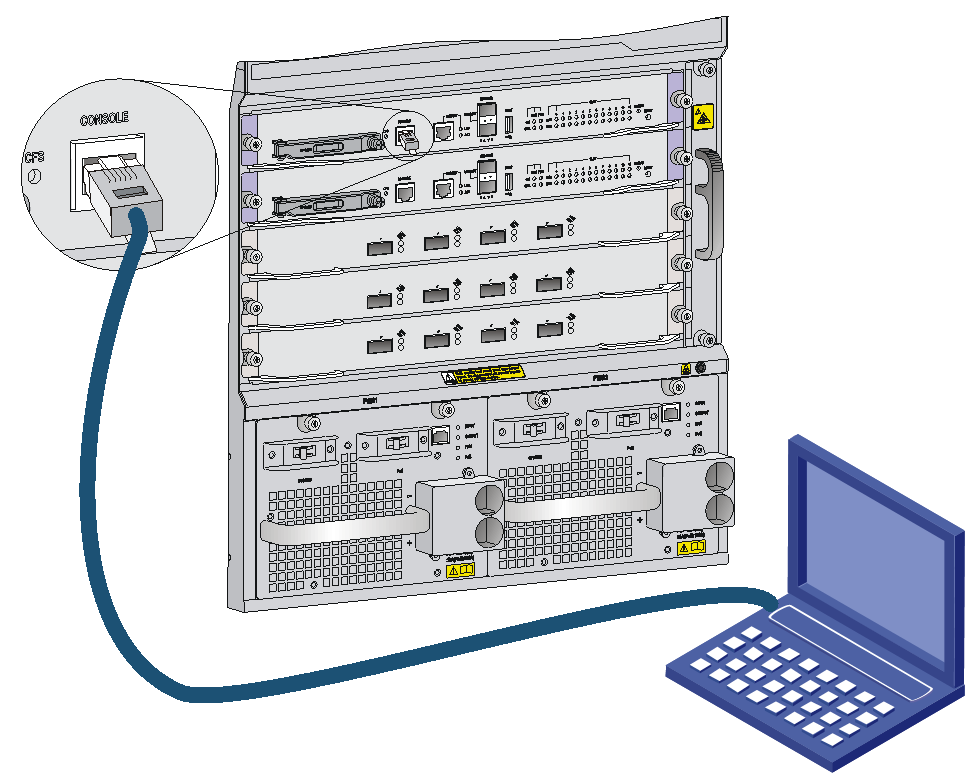
2. Identify the mark on the console port and connect the RJ-45 connector of the console cable to the console port of the router.
Figure 1 Connecting a console port to a terminal
Setting terminal parameters
To access the device through the console port, you must run a terminal emulator program (TeraTermPro, PuTTY, or Tera Term) on the configuration terminal. For information about how to use a terminal emulator program, see the program's user guide.
The following are the required terminal settings:
· Baud rate—9600.
· Data bits—8.
· Stop bits—1.
· Parity—none.
· Flow control—none.
Powering on the router
Before powering on the router, verify the following items:
· The router has been steadily mounted.
· All the cards have been correctly installed.
· All the communication cables, fibers, power cords, and grounding cables have been correctly connected.
· The input power voltage meets the requirement of the router.
· The console cable has been correctly connected.
· The configuration terminal has been started, and the terminal parameters have been configured.
To power on the router:
1. Turn on the power source of the router.
The output displayed on the terminal varies by router software versions. The following is a sample output you can see on the terminal:
System is starting...
Press Ctrl+D to access BASIC-BOOTWARE MENU...
Press Ctrl+T to start memory test
Booting Normal Extended BootWare
The Extended BootWare is self-decompressing.........Done.
…
BootWare Validating...
Press Ctrl+B to access EXTENDED-BOOTWARE MENU...
2. Enter 1.
The system image file is loaded.
Enter your choice(0-9): 1
Loading the main image files...
Loading file flash:/temp-system.bin...........................
............................................................................
............................................................................
.............................Done.
Loading file flash:/temp-boot.bin.............................
......Done.
Image file flash:/temp-system.bin is self-decompressing.........
................................................................Done.
System image is starting...
Finished running batch file.
Line con0 is available.
Press ENTER to get started.
When the prompt <Sysname> appears, you can configure the router.
After powering on the router, verify the following items:
· The cooling system is operating. You can hear fan rotating noise and feel air being blown out.
· All the system status LEDs on the MPUs show that the system is operating correctly. For more information about the LED status, see "MPU LEDs."
Configuring the router
By default, the router does not authenticate the console login user at an AUX interface. To increase system security and enable remote management:
· Configure remote access services, for example, Telnet, SSH or NMS.
· Configure authentication on each user interface, including the AUX interfaces.
Configuring authentication on a user interface
You can configure authentication on a user interface to control access to the router.
Table 1 describes the Telnet login authentication methods available for a VTY user interface.
Table 1 Telnet login authentication methods
|
Authentication method |
Feature |
Application scenarios |
|
None |
Easy to configure, allows any user to Telnet to your router, and lowest in security |
Lab environments and extremely secure network environments |
|
Password |
Easy to configure, secure, and flat user management |
Environments that do not need granular privilege management |
|
Username and password |
Complex to configure, secure, and hierarchical user management |
Environments where multiple operators cooperate to manage the router |
For more information about login methods, see login management in H3C SR8800-F Routers Fundamentals Configuration Guide.
Verifying the network configuration
Execute display commands in any view.
|
Task |
Command |
|
Display the name, model, and running operating system version of the router |
display version |
|
Display the current configuration of the router |
display current-configuration |
|
Display the interface status and configuration |
display interface brief |
|
Display the IP configuration information of the specified or all Layer 3 interfaces |
display ip interface brief |
|
Display information about active routes in the routing table |
display ip routing-table |
|
Display neighbor discovery protocol (NDP) configuration information |
display ndp |
Connecting the router to the network
Before you connect the router to the network, configure basic settings for the router. For more information, see login management in H3C SR8800-F Routers Fundamentals Configuration Guide.
Connecting your router to the network through twisted pair cables
The router provides 10/100BASE-TX and 1000BASE-T ports. These ports use RJ-45 connectors and support auto-MDI/MDI-X. Use twisted pair cables of category-5 or above to connect the Ethernet ports of your router to the network. For more information about twisted pair cables, see "Ethernet twisted pair cable."
To connect your router to the network through a twisted pair cable:
1. Connect one end of the twisted pair cable to the RJ-45 Ethernet port of your router.
2. Connect the other end of the twisted pair cable to the RJ-45 Ethernet port of the access device in the network.
3. Check that the port LED status is correct.
For more information about the LED status, see "Appendix C LEDs."
Connecting your router to the network through optical fibers
|
|
WARNING! Disconnected optical fibers or transceiver modules might emit invisible laser light. Do not stare into beams or view directly with optical instruments when the switch is operating. |
Before connecting optical fibers to a fiber port, install a transceiver module in the port. For information about installing transceiver modules, see "(Optional) Installing transceiver modules". For more information about optical fibers, see "Optical fiber."
To connect your router to the network through an optical fiber:
1. Install the transceiver modules into the fiber ports of the router and the peer device.
2. Remove the dust covers of the optical fiber connectors, and clean both ends of the optical fiber.
3. Connect the optical fiber to the transceiver modules:
a. Remove the dust plugs of the transceiver modules.
b. Connect one end of the optical fiber to the transceiver module in the router.
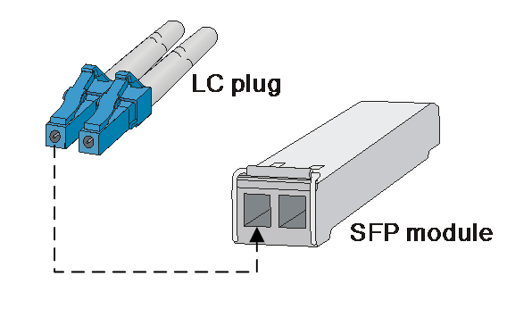
c. Connect the other end to the transceiver module in the peer device.
Figure 2 Connecting an LC optical fiber connector to an SFP module
4. Verify that the port LED status is correct.
For more information about the LED status, see "Appendix C LEDs."
|
|
NOTE: The transceiver modules each require two optical fibers. The transmitter (TX) port on one end must connect to the receiver (RX) port on the other end. |
Testing connectivity
When the router is connected to the network, use the ping or tracert command to test the network connectivity. For more information about the two commands, see system maintenance and debugging commands in H3C SR8800-F Routers Network Management and Monitoring Command Reference.
