- Table of Contents
-
- H3C SR8800-F Router Series Installation Guide-5W104
- 00-Preface
- 01-Chapter 1 Preparing for Installation
- 02-Chapter 2 Installing the Router
- 03-Chapter 3 Installing FRUs
- 04-Chapter 4 Connecting Your Router to the Network
- 05-Chapter 5 Troubleshooting
- 06-Chapter 6 Replacement Procedures
- 07-Appendix A Chassis Views and Technical Specifications
- 08-Appendix B FRUs and Compatibility Matrixes
- 09-Appendix C LEDs
- 10-Appendix D Slot arrangement and port numbering
- 11-Appendix E Cables
- 12-Appendix F Cable Management
- 13-Appendix G Engineering Labels for Cables
- Related Documents
-
| Title | Size | Download |
|---|---|---|
| 03-Chapter 3 Installing FRUs | 3.30 MB |
Contents
Installing MPUs/service modules
Installing the power supply system
Installing a power supply adapter
Installing a power supply in the chassis
(Optional) Installing a CF card for an MPU
(Optional) Installing a transceiver module
Installing an XFP/QSFP+/SFP+/SFP/QSFP28 transceiver module
Installing a CFP transceiver module
Installing FRUs
There is no required order for installing FRUs. As a best practice, connect power cords after completing installing all required FRUs.
Keep the chassis and the component packages for future use.
Attaching an ESD wrist strap
The router is provided with an ESD wrist strap. To minimize ESD damage to electronic components, wear an ESD wrist strap and make sure it is reliably grounded when installing modules.
To use an ESD wrist strap:
1. Make sure the router is reliably grounded. For how to ground your router, see "Grounding the router."
2. Wear the wrist strap.
3. Tighten the wrist strap to keep good skin contact. Make sure the resistance reading between your body and the ground is between 1 and 10 megohms.
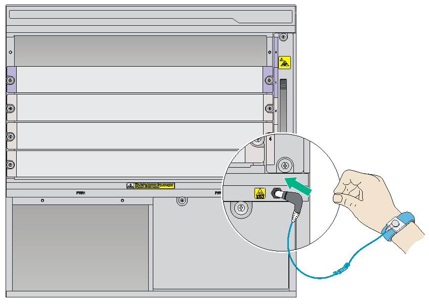
4. As shown in Figure 1, attach the ESD wrist strap to the chassis by either of the following methods:
¡ Insert the ESD wrist strap into the ESD socket on the chassis.
¡ Attach the ESD wrist strap to the grounding post of the chassis with an alligator clip.
Figure 1 Attaching an ESD wrist strap (SR8805-F)
Installing MPUs/service modules
|
|
CAUTION: Before installing a card in the chassis, make sure the connectors on the card are not broken or blocked to avoid damaging the backplane. |
|
|
IMPORTANT: · To ensure good ventilation, install a filler panel over an empty MPU or service module slot. MPU slots use different filler panels than service module slots. · The MPUs and service modules of the router are shipped with protection boxes. Before you install an MPU or service module, pull the ejector levers on the card outward, and then pull it out of the protection box. |
The MPUs and service modules available for the router are hot swappable. The installation procedure is similar for MPUs and service modules. Unless otherwise stated, MPUs and service modules are collectively referred to as "cards" in this document.
To install a card:
1. Wear an ESD wrist strap, and make sure it has a good skin contact and is reliably grounded. For more information, see "Attaching an ESD wrist strap."
2. Remove the filler panel (if any) from the slot. Keep the filler panel for future use.
3. Press the ejector levers down to the horizontal level.
Skip this if the card to be installed is not a base card.
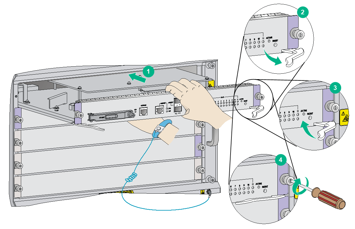
4. As shown by callout 1 in Figure 2, hold the card by the front panel with one hand and support the card bottom with the other. Slide the card steadily into the slot along the guide rails.
5. As shown by callout 2 in Figure 2, when most part of the card is inserted in the slot, press the ejector levers on the card outward.
6. Push the card until the positioning pin on card touches the hole on the chassis.
7. As shown by callout 3 in Figure 2, press the ejector levers inward until the ejector levers touch the panel tightly and the card seats into the backplane.
8. As shown by callout 4 in Figure 2, fasten the captive screws on the card.
9. Push the ejector levers up to the vertical level.
Skip this if the card to be installed is not a base card.
10. When the router is powered on, verify the running status of the card by using either of the following methods:
¡ Examine the card status LED (SLOT) on the MPU. If the RUN LED flashes, the card in the slot operates correctly. For more information about card status LED (SLOT), see "Card status LEDs."
¡ Verify the card operating status at the CLI. For more information, see device management in H3C SR8800-F Routers Fundamentals Command Reference.
Figure 2 Installing a card (MPU)
Installing a subcard
|
|
CAUTION: To ensure good ventilation, install filler panels in unused slots. |
This section describes how to install a subcard on a base card. The base card installation procedure is the same as the card installation procedure (see "Installing MPUs/service modules").
The subcards are hot swappable.
To install a subcard:
1. Wear an ESD wrist strap, and make sure it has a good skin contact and is reliably grounded. For more information, see "Attaching an ESD wrist strap."
2. Make sure the base card is installed in the router.
3. Unpack the subcard.
4. Install the subcard in the base card:
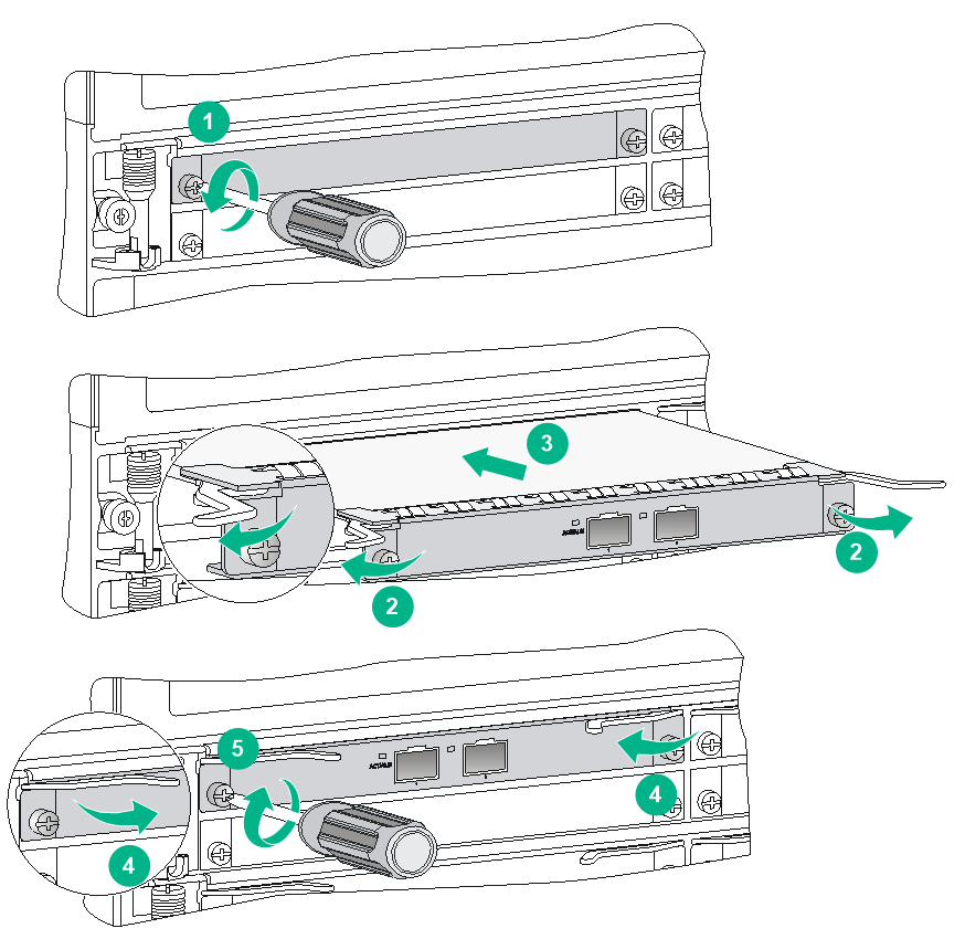
a. Remove the filler panel (if any) from the target slot on the base card, as shown by callout 1 in Figure 3.
Keep the removed filler panel secure for future use.
b. Open the ejector levers on the subcard, as shown by callout 2 in Figure 3.
c. Gently push the subcard (with bottom up) into the slot along the guide rails until the ejector levers of the subcard touch the base card panel, as shown by callout 3 in Figure 3.
d. Push the front panel of the subcard forward. Then close the ejector levers so that the subcard is flush with the base card, as shown by callout 4 in Figure 3.
e. Use a Phillips screwdriver to fasten the screws on the subcard, as shown by callout 5 in Figure 3.
Figure 3 Installing a subcard
Installing the power supply system
|
|
WARNING! Provide a circuit breaker for each power supply. |
|
|
CAUTION: In case of dual grid inputs, make sure the amplitude, phase, and frequency of the input voltage of the two grids are the same. |
The switch uses 1+1 power redundancy and supports dual grid inputs. You can supply either AC or DC power for the switch. For information about the power supplies available for the switch, see "Power supplies."
To use a power adapter, first install it in the chassis and then install power supplies in the power adapter. For how to install a power supply in a power adapter, see "Installing a power supply in the chassis."
Installing a power supply adapter
|
|
CAUTION: Do not install power supply adapters of different models on the same switch. |
To install a power supply adapter:
1. Wear an ESD wrist strap and make sure it makes good skin contact and is reliably grounded. For more information, see "Attaching an ESD wrist strap."
2. Unpack the power supply adapter.
3. Holding the adapter handle with one hand and supporting the adapter bottom with the other, slide the adapter all the way into the chassis along the guide rails. Make sure the adapter is firmly seated in the chassis and has good contact with the backplane connectors.
To avoid damaging the power supply adapter and the backplane connectors, remove the adapter, realign it with the chassis, and insert it again in case of misalignment.
4. Use a Phillips screwdriver to fasten the captive screws on the adapter to secure the adapter in the chassis.
If you cannot fasten the captive screws tightly, check the adapter installation.
Figure 4 Installing a power supply adapter (LSQM1PWRSPB)
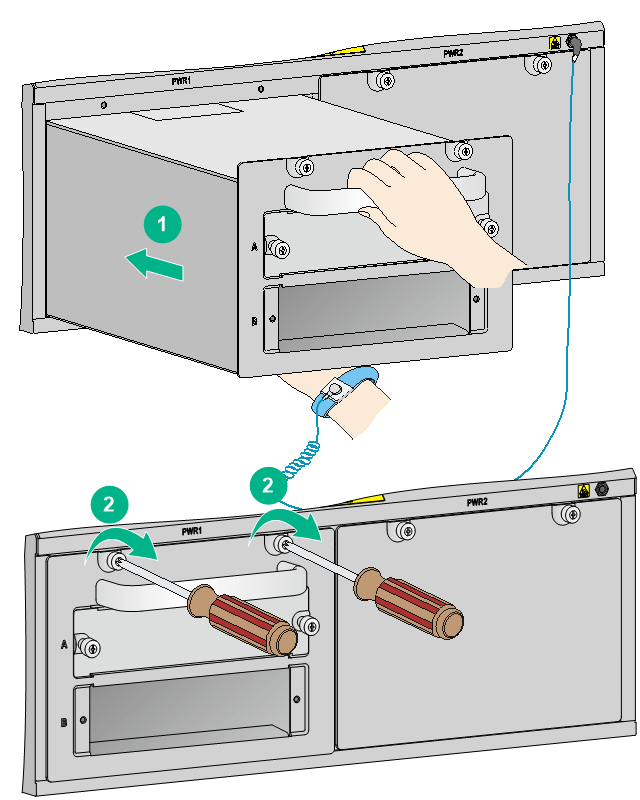
Installing a power supply in the chassis
|
|
CAUTION: · Before installing a power supply, make sure the switch on the power supply is in the OFF position. · Do not install power supplies of different models on the same switch. · Make sure the outputs of the power supplies to be installed can satisfy the requirements of the switch. · To avoid damaging a power supply, move the power supply by supporting its bottom rather than holding its handle. |
To install a power supply:
1. Wear an ESD wrist strap and make sure it has a good skin contact and is reliably grounded. For more information, see "Attaching an ESD wrist strap."
2. Remove the filler panel (if any) from the target slot.
Keep the filler panel secure for future use.
3. Unpack the power supply, and verify that the model is correct.
4. Insert the power supply with its upside up into the slot:
a. Grasp the handle of the module with one hand and support the module bottom with the other.
b. Gently push the power supply along the guide rails into the slot to firmly seat it into the backplane, as shown by callout 1 in Figure 5.
When a misalignment occurs, pull out the power supply first, and push it in again to avoid damage to the power supply and the connection terminals on the backplane.
5. Fasten the captive screws on the power supply to secure the power supply into the chassis, as shown by callout 2 in Figure 5.
If the captive screws cannot be fastened tightly, do not fasten them forcibly. Check the power supply installation.
Figure 5 Installing a power supply (PSR1400-D)

Connecting the power cord
|
|
WARNING! Before connecting the power cord for a power supply, make sure the switch on the power supply is turned off. |
Table 1 Power cord connection for SR8800-F routers
|
Model |
Power input (AC/DC) |
Description |
|
PSR320-A |
AC |
Connecting the power cord for a PSR320-A/PSR650-A power supply |
|
PSR650-A |
AC |
|
|
PSR1200-A |
AC |
|
|
PSR1400-A |
AC |
|
|
PSR2500-12AHD |
AC |
|
|
PSR650-D |
DC |
|
|
PSR1200-D |
DC |
|
|
PSR1400-D |
DC |
Connecting the power cord for a PSR1400-D/PSR2500-12D power supply |
|
PSR2500-12D |
DC |
|
|
IMPORTANT: The equipment room typically uses 10A power strips. However, the PSR1200-A, PSR1400-A, and PSR2500-12AHD power supplies use 16A AC power cords. To use PSR1200-A, PSR1400-A, and PSR2500-12AHD power supplies, prepare a 16A power strip and make sure the AC power supply system can provide enough power. For information about power cord plugs and connectors used in different countries or regions, see "AC power cords." |
Connecting the power cord for a PSR320-A/PSR650-A power supply
1. Insert the two ends of the bail latch to the holders on the left of the power socket. Then pull the bail latch to the left.
2. Unpack the power cord, and make sure the model is correct.
Both the PSR320-A and PSR650-A use a 10A AC power cord.
3. Connect the female connector of the power cord to the power receptacle on the power supply, and ensure good contact.
4. Pull the bail latch to the right to retain the power cord.
5. Connect the other end of the power cord to an AC power source.
6. Switch on the power supply.
7. Verify the power supply status LED:
¡ If the LED is green, the power cord is correctly connected.
¡ If the LED is off or red, power off the power supply, verify the installation, locate the fault, and resolve the problem. Switch on the power supply and verify that the LED is green. For information about the PSR320-A/PSR650-A status LEDs, see "PSR320-A/PSR650-A/PSR650-D/PSR1200-A/PSR1200-D power supply LED."
Figure 6 Connecting the power cord for a PSR320-A/PSR650-A power supply
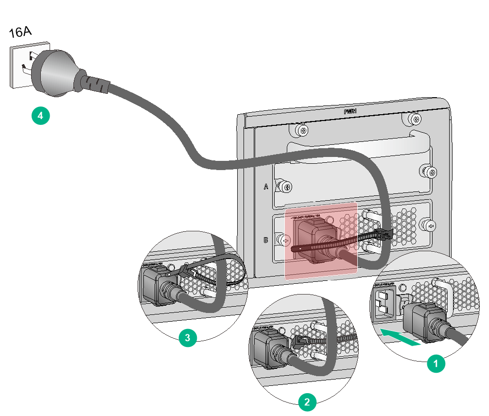
Connecting the power cord for a PSR1200-A power supply
1. Unpack the power cord, and verify the power cord model is correct.
The PSR1200-A power supply uses a 16A AC power cord.
2. Connect the power cord to the power socket, and ensure a good contact.
3. Use a releasable cable tie to secure the power cord to the handle of the power supply.
4. Connect the other end of the power cord to the AC power source.
Figure 7 Connecting the power cord for a PSR1200-A power supply
Connecting the power cord for a PSR1400-A power supply (using a releasable cable tie to secure the power cord)
The accessories provided with the power supply are different in batches. If a releasable cable tie is provided with the power supply, follow this procedure to connect and secure the power cord.
To connect the power cord for a PSR1400-A power supply (using a releasable cable tie to secure the power cord):
1. Unpack the power cord, and make sure the model is correct.
The PSR1400-A uses a 16A AC power cord.
2. Connect the female connector of the power cord to the power receptacle on the power supply, and ensure good contact.
3. Use a releasable cable tie to secure the power cord to the handle of the power supply.
4. Connect the other end of the power cord to an AC power source.
5. Switch on the power supply.
6. Verify the power supply input status LED (INPUT):
¡ If the LED is green, the power cord is correctly connected.
¡ If the LED is off or red, verify the installation, locate the fault, and resolve the problem. Switch on the power supply to verify that the LED is green. For information about the PSR1400-A status LEDs, see "PSR1400-A/PSR2500-12AHD/PSR2500-12D power supply LEDs."
Figure 8 Connecting the power cord for a PSR1400-A power supply (using a releasable cable tie to secure the power cord)

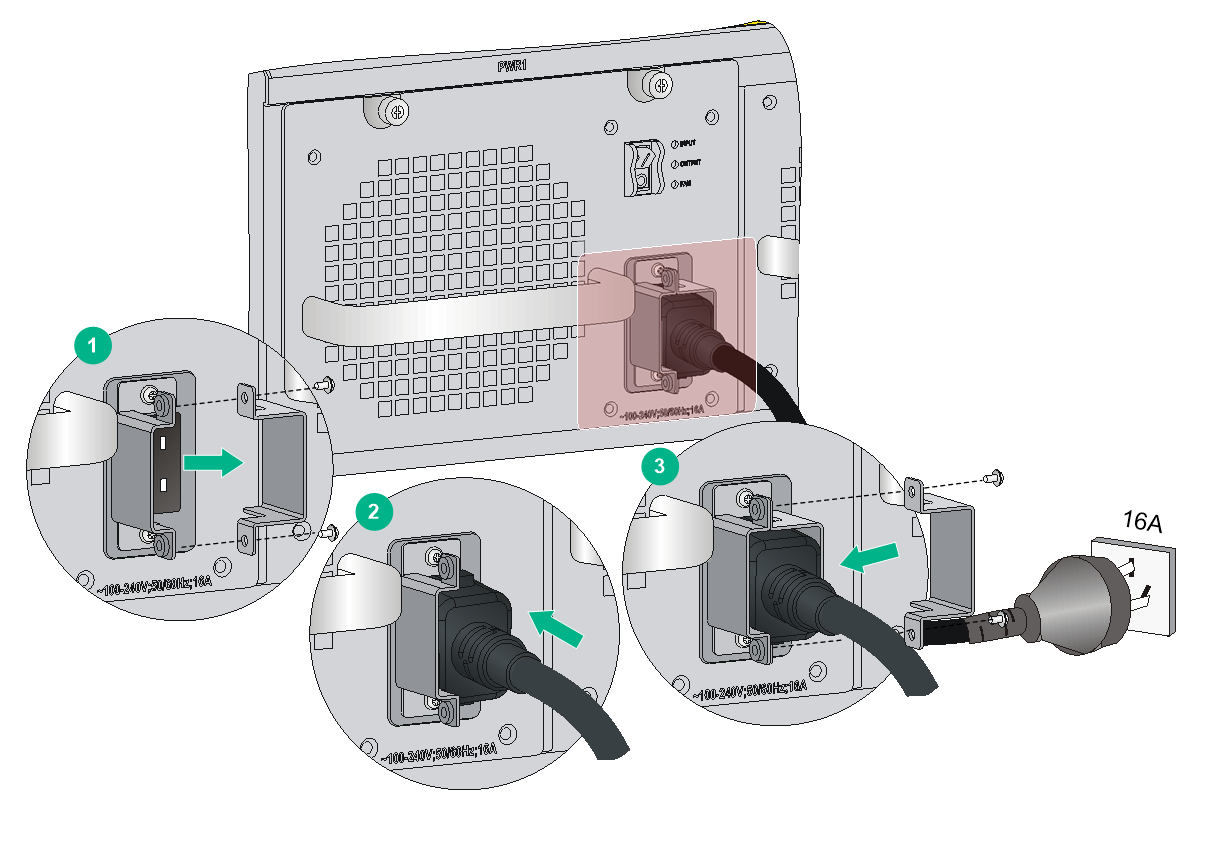
Connecting the power cord for a PSR1400-A power supply (using a power cord retainer suite to secure the power cord)
The accessories provided with the power supply are different in batches. If a power cord retainer suite is provided with the power supply, follow this procedure to connect and secure the power cord.
To connect the power cord for a PSR1400-A power supply (using a power cord retainer suite to secure the power cord):
1. Unpack the power cord, and make sure the model is correct.
The PSR1400-A uses a 16A AC power cord.
2. Use a Phillips screwdriver to remove the screws from the power cord retainer suite and remove the right part of the retainer suite.
3. Connect the female connector of the power cord to the power receptacle on the power supply, and ensure good contact.
4. Secure the right part of the power cord retainer suite to retain the power cord.
5. Connect the other end of the power cord to an AC power source.
6. Switch on the power supply.
7. Verify the power supply input status LED (INPUT):
¡ If the LED is green, the power cord is correctly connected.
¡ If the LED is off or red, verify the installation, locate the fault, and resolve the problem. Switch on the power supply to verify that the LED is green. For information about the PSR1400-A status LEDs, see "PSR1400-A/PSR2500-12AHD/PSR2500-12D power supply LEDs."
Figure 9 Connecting the power cord for a PSR1400-A power supply (using a power cord retainer suite to secure the power cord)
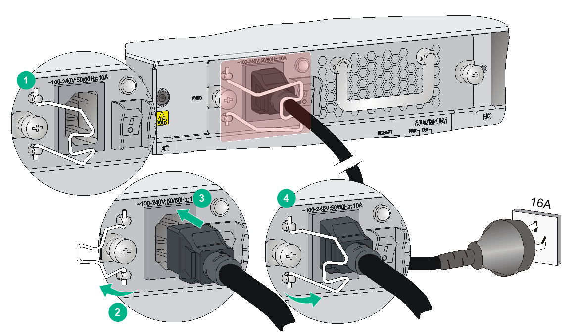
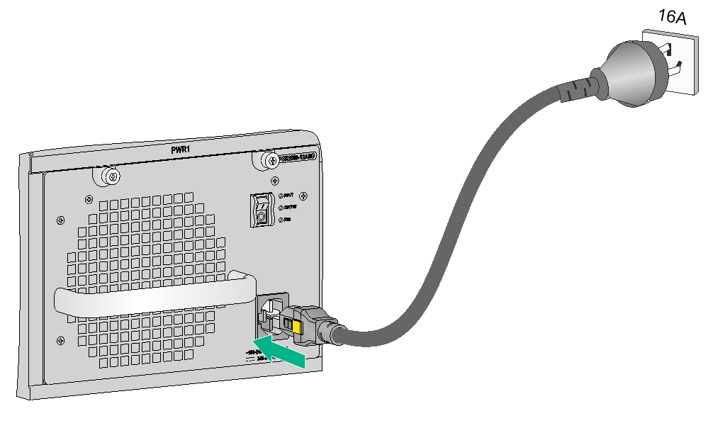
Connecting the power cord for a PSR2500-12AHD power supply
1. Unpack the power cord and make sure the power cord model is correct.
The PSR2500-12AHD power supply uses a 16A AC power cord or a high-voltage DC power cord.
2. Connect the female connector of the power cord to the power receptacle on the power supply. Push the tab on the connector to secure the connector in position.
3. Connect the other end of the power cord to a power source.
Figure 10 Connecting a 16A AC power cord for a PSR2500-12AHD power supply
Connecting the power cord for a PSR650-D power supply
|
|
WARNING! Before connecting the DC power cord for a PSR650-D power supply, make sure the DC power source circuit breakers are turned off. |
To connect the power cord for a PSR650-D power supply:
1. Remove the protection cover from the power supply.
2. Loosen the screws on the wiring terminals with a Phillips screwdriver.
3. Connect the end of the blue DC power cord marked with – to the negative terminal (–) on the power supply and fasten the screw.
4. Connect the end of the black DC power cord marked with + to the positive terminal (+) on the power supply and fasten the screw.
5. Put the protection cover on the wiring terminals.
6. Connect the other ends of the DC power cords to a DC power source.
Figure 11 Connecting the power cord for a PSR650-D power supply
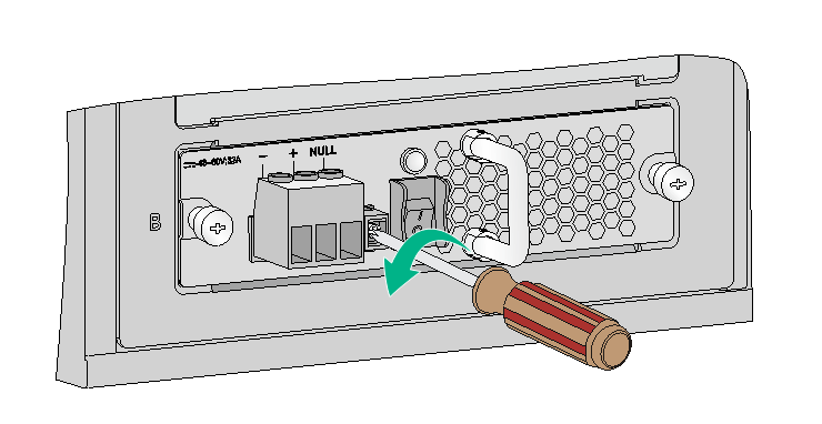
Connecting the power cord for a PSR1200-D power supply
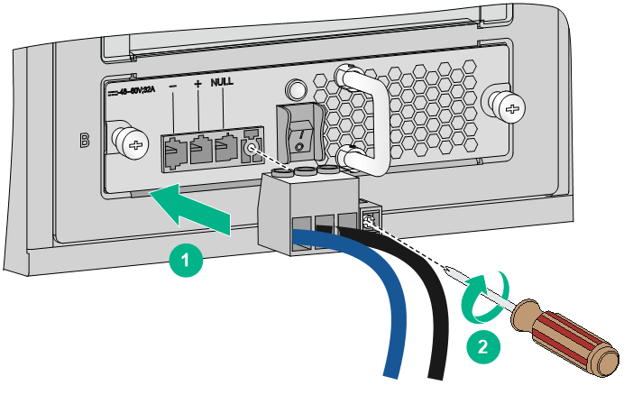
1. Loosen the captive screw that secures the terminal block plug to the chassis and remove the terminal block plug.
Figure 12 Removing the terminal block plug
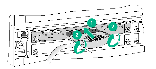
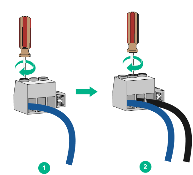
2. Unpack the DC power cord provided with the power supply. Insert the wire marked with – to the negative terminal (–) on the terminal block and fasten the screw. Insert the wire marked with + to the positive terminal (+) and fasten the screw.
Figure 13 Inserting the DC power cord into the terminal block plug
3. Correctly orient the terminal block plug and insert it into the power supply. Use a Phillips screwdriver to fasten the screw on the plug.
Figure 14 Attaching the terminal block plug to the power supply
4. Connect the other end of the DC power cord to the DC power source. Use a releasable cable tie to secure the DC power cord to the nearby rack post.
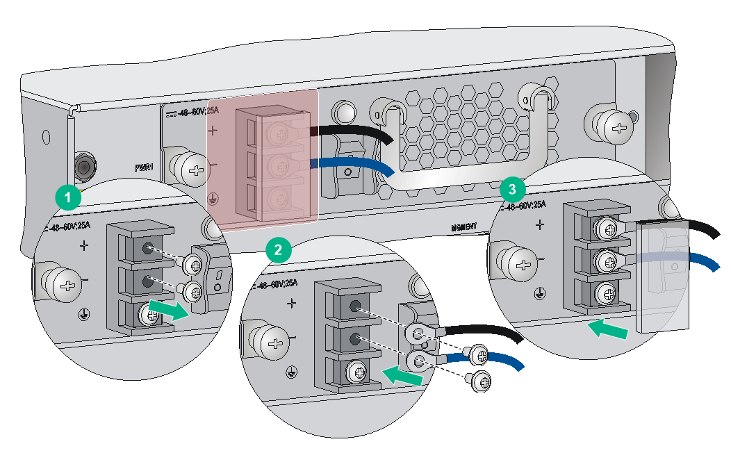
Connecting the power cord for a PSR1400-D/PSR2500-12D power supply
|
|
WARNING! Before connecting the power cord for a PSR1400-D/PSR2500-12D power supply, make sure the DC power source circuit breakers are turned off. |
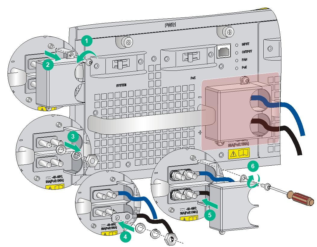
The power cord connection procedure is similar for the PSR1400-D and PSR2500-12D power supplies. The following procedure uses the PSR1400-D power supply as an example.
To connect the power cords for the PSR1400-D:
1. Loosen the screws on the protection cover with a Phillips screwdriver and remove the protection cover.
2. Loosen the M6 nuts on four wiring terminals with a M6 socket wrench. Remove the M6 nut, spring washer, and one flat washer in turn from each wiring terminal.
3. Connect the end of the blue DC power cord marked with – to the negative terminal (–) on the power supply.
4. Connect the end of the black DC power cord marked with + to the positive terminal (+) on the power supply.
5. Put the flat washer and spring washer on the wiring terminal in turn and screw up the M6 nut with the M6 socket wrench. Repeat this step for the other three terminals.
6. Put the protection cover on the wiring terminals and faster the screws.
7. Connect the other ends of the DC power cords to a DC power source.
Figure 15 Connecting the power cord for a PSR1400-D power supply
(Optional) Installing a CF card for an MPU
An MPU with a CF card protection cover is shipped with a CF card. Figure 16 shows a CF card slot with the protection cover.
Figure 16 CF card slot view (with the protection cover)
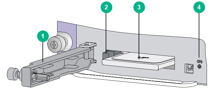
|
(1) CF card protection cover |
(2) CF card eject button |
|
(3) CF card |
(4) CF card status LED (CFS) |
You can install a CF card for an MPU that supports CF cards but does not have CF card protection cover.
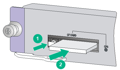
To install a CF card:
1. Push the CF card eject button all the way and make sure the button does not reset automatically.
2. Push the CF card all the way into the CF card slot until the CF card eject button resets.
3. After the router is powered on, you can verify the running status of the CF card by using either of the following methods:
¡ Verify the status of the CFS LED on the MPU. If the LED is steady on, the CF card is installed correctly. For more information about the CFS LED, see "CF card status LED."
¡ Verify the CF card running status at the CLI. For more information, see "Hardware management and maintenance."
Figure 17 Installing a CF card
(Optional) Installing a transceiver module
|
|
WARNING! Do not stare into any open apertures of operating transceiver modules or optical fiber connectors. The laser light emitted from these apertures might hurt your eyes. |
|
|
CAUTION: · During the installation or removal process, be careful not to touch the golden plating on the transceiver module. · Before inserting a transceiver module into a port, make sure the transceiver module aligns with the port correctly. · If a transceiver module has a fiber connected, remove the fiber before installing the transceiver module. |
Installing an XFP/QSFP+/SFP+/SFP/QSFP28 transceiver module
The installation procedure is similar for XFP, QSFP+, QSFP28, SFP+, and SFP transceiver modules. The following uses an SFP+ transceiver module for illustration.
To install an SFP+ transceiver module:
1. Wear an ESD wrist strap and make sure it makes good skin contact and is reliably grounded. For more information, see "Attaching an ESD wrist strap."
2. Remove the dust plug from the target fiber port.
3. As shown in Figure 18, close the bail latch upward to catch the knob on the top of the transceiver module. Then correctly orient the transceiver module and align it with the fiber port, and push it gently into the port until you feel it snap into place.
Transceiver modules and fiber ports have disorientation rejection designs. If you cannot insert a transceiver module easily into a port, the orientation might be wrong. Remove and reorient the transceiver module.
In case of limited space, you can gently push against the front face of the transceiver module instead of the two sides.
4. If you are not to install an optical fiber, insert a dust plug into the transceiver module bore.
5. Connect a fiber to the module. For the installation procedure, see "Connecting the router to the network."
Figure 18 Installing an SFP+ transceiver module

|
|
NOTE: The triangular pin on a transceiver module and the hole in a fiber port function together to prevent the module from disengaging from the port. |
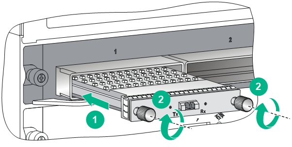
Installing a CFP transceiver module
1. Wear an ESD wrist strap and make sure it makes good skin contact and is reliably grounded. For more information, see "Attaching an ESD wrist strap."
2. Remove the dust plug from the target fiber port.
3. As shown in Figure 19, correctly orient the transceiver module and align it with the fiber port. Push it gently into the port until you feel it snaps into place.
Transceiver modules and fiber ports have disorientation rejection designs. If you cannot insert a transceiver module easily into a port, the orientation might be wrong. Remove and reorient the transceiver module.
In case of limited space, you can gently push against the front face of the transceiver module instead of the two sides.
4. Fasten the captive screws on the transceiver module to secure it in place.
If a screw cannot be fastened, adjust the CFP module and the screw and re-fasten the screw, or remove the CFP module and then reinstall it.
5. Connect a fiber to the module. For the installation procedure, see "Connecting the router to the network."
Figure 19 Installing a CFP transceiver module
Connecting an E1 cable
1. Wear an ESD wrist strap and make sure it makes good skin contact and is reliably grounded.
For more information, see "Attaching an ESD wrist strap."
2. Connect the HD96 connector of the E1 cable to the interface on the subcard and use a screwdriver to fasten the screws on the connector.
3. Connect the other end of the E1 cable to the peer device.
Figure 20 Installing an E1 cable