- Table of Contents
-
- 15-Network Management and Monitoring Configuration Guide
- 00-Preface
- 01-System maintenance and debugging configuration
- 02-NQA configuration
- 03-iNQA configuration
- 04-iFIT configuration
- 05-SRPM configuration
- 06-NTP configuration
- 07-PTP configuration
- 08-Network synchronization configuration
- 09-SNMP configuration
- 10-RMON configuration
- 11-NETCONF configuration
- 12-CWMP configuration
- 13-EAA configuration
- 14-Process monitoring and maintenance configuration
- 15-Sampler configuration
- 16-Mirroring configuration
- 17-NetStream configuration
- 18-IPv6 NetStream configuration
- 19-TCP connection trace configuration
- 20-Performance management configuration
- 21-Fast log output configuration
- 22-Flow log configuration
- 23-Information center configuration
- 24-Packet capture configuration
- 25-Flow monitor configuration
- Related Documents
-
| Title | Size | Download |
|---|---|---|
| 07-PTP configuration | 539.21 KB |
Contents
Grandmaster clock selection and master-member/subordinate relationship establishment
Restrictions and guidelines: PTP configuration
Configuring PTP (IEEE 1588 version 2)
Configuring PTP (ITU-T G.8275.1)
Configuring PTP (ITU-T G.8275.2)
Specifying PTP for obtaining the time
Configuring an OC to operate only as a member clock
Specifying a PTP technical standard
Enabling the PTP clock state feature
Configuring the role of a PTP port
Configuring the mode for carrying timestamps
Specifying a delay measurement mechanism
Configuring one of the ports on a TC+OC clock as an OC-type port
Enabling NotSlave on a PTP port
Enabling unicast negotiation on PTP ports
Configuring PTP message transmission and receiving
Setting the interval for sending Pdelay_Req messages
Setting the interval for sending Sync messages
Setting the minimum interval for sending Delay_Req messages
Setting the interval for sending Delay-Resp messages
Configuring parameters for PTP messages
Specifying the IPv4 UDP transport protocol for PTP messages
Configuring a source IP address for multicast PTP messages transmitted over IPv4 UDP
Configuring a destination IP address for unicast PTP messages transmitted over IPv4 UDP
Configuring the destination MAC address for PTP messages
Setting a DSCP value for PTP messages transmitted over IPv4 UDP
Specifying a VLAN tag for PTP messages
Specifying the maximum number of removed steps (clock nodes) from the GM to the device
Enabling the device to notify the downstream nodes of its time synchronization state
Adjusting and correcting clock synchronization
Setting the delay correction value
Calculating the TAI based on the UTC time
Configuring ToD input or output
Enabling the device to ignore the synchronizationUncertain flag
Setting clock source parameters
Configuring a priority for a clock (IEEE 1588 version 2)
Configuring a priority for a clock (ITU-T G.8275.1 and ITU-T G.8275.2)
Enabling SNMP notification for the PTP module
Display and maintenance commands for PTP
Example: Configuring PTP (IEEE 1588 version 2, IPv4 UDP transport, multicast transmission)
Example: Configuring PTP (IEEE 1588 version 2, IPv4 UDP transport, unicast transmission)
Example: Configuring PTP (ITU-T G.8275.1, IEEE 802.3/Ethernet transport, multicast transmission)
Example: Configuring PTP (ITU-T G.8275.2, IPv4 UDP encapsulation, unicast transmission)
Configuring PTP
About PTP
Precision Time Protocol (PTP) provides time synchronization among devices with submicrosecond accuracy. It provides also precise frequency synchronization.
Basic concepts
PTP profile
PTP profiles (PTP standards) include:
· IEEE 1588 version 2—1588v2 defines high-accuracy clock synchronization mechanisms. It can be customized, enhanced, or tailored as needed. 1588v2 is the latest version.
· ITU-T G.8275.1—G.8275.1 is introduced based on IEEE 1588. It is a precision time protocol telecom profile for phase and time synchronization with full timing support from the network.
· ITU-T G.8275.2—G.8275.2 is introduced based on IEEE 1588. It uses the client-server architecture, with the member clock nodes as clients and the master clock node as the server.
The clients and server first exchange Layer 3 unicast messages to establish clock links and then exchange PTP messages for the clients to be synchronized to the server.
The communication between the clients and server can traverse a Layer 2 network. Make sure a maximum of three Layer 2 devices exist on the communication path. The Layer 2 devices do not need to support PTP.
To ensure stable PTP message processing and time synchronization accuracy, do not use Layer 3 interfaces or Layer 2 interfaces converted from Layer 3 interfaces to connect the clients and server.
PTP domain
A PTP domain refers to a network that is enabled with PTP. A PTP domain has only one reference clock called "grandmaster clock (GM)." All devices in the domain synchronize to the clock.
Clock node and PTP port (IEEE 1588 version 2)
A node in a PTP domain is called a clock node. A port enabled with PTP is called a PTP port. IEEE 1588 version 2 defines the following types of basic clock nodes:
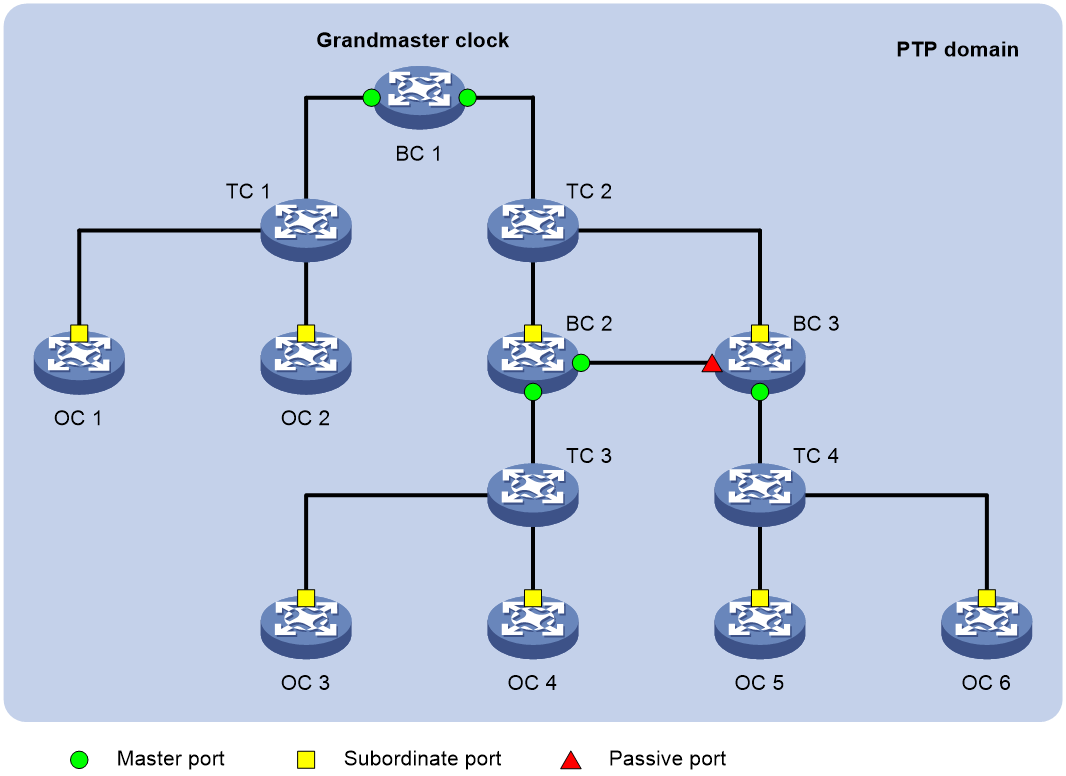
· Ordinary Clock (OC)—A PTP clock with a single PTP port in a PTP domain for time synchronization. It synchronizes time from its upstream clock node through the port. If an OC operates as the clock source, it sends synchronization time through a single PTP port to its downstream clock nodes.
· Boundary Clock (BC)—A clock with more than one PTP port in a PTP domain for time synchronization. A BC uses one of the ports to synchronize time from its upstream clock node. It uses the other ports to synchronize time to the relevant downstream clock nodes. If a BC operates as the clock source, such as BC 1 in Figure 1, it synchronizes time through multiple PTP ports to its downstream clock nodes.
· Transparent Clock (TC)—A TC does not keep time consistency with other clock nodes. A TC has multiple PTP ports. It forwards PTP messages among these ports and performs delay corrections for the messages, instead of performing time synchronization. TCs include the following types:
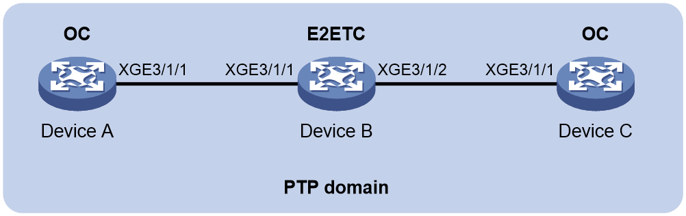
¡ End-to-End Transparent Clock (E2ETC)—Forwards non-P2P PTP messages in the network and calculates the delay of the entire link.
¡ Peer-to-Peer Transparent Clock (P2PTC)—Forwards only Sync, Follow_Up, and Announce messages, terminates other PTP messages, and calculates the delay of each link segment.
Figure 1 shows the positions of these basic clock nodes in a PTP domain.
Figure 1 Clock nodes and PTP ports in a PTP domain (IEEE 1588 version 2)
In addition to these basic types of clock nodes, PTP introduces hybrid clock nodes. For example, a TC+OC has multiple PTP ports in a PTP domain. One port is the OC type, and the others are the TC type.
A TC+OC forwards PTP messages through TC-type ports and performs delay corrections. In addition, it synchronizes time through its OC-type port. TC+OCs include these types: E2ETC+OC and P2PTC+OC.
Clock node and PTP port (ITU-T G.8275.1)
A node in a PTP domain is a clock node. A port enabled with PTP is a PTP port.
ITU-T G.8275.1 defines the following types of basic clock nodes:
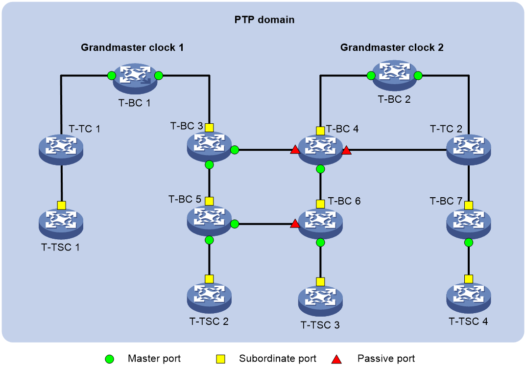
· Telecom boundary clock (T-BC)—A clock node with more than one PTP port in a PTP domain for time synchronization. It uses one of the ports to synchronize time to its upstream clock node and uses the other ports to distribute time to the downstream clock nodes. If a T-BC operates as the clock source, it distributes time through multiple PTP ports to its downstream clock nodes.
· Telecom transparent Clock (T-TC)—A clock code that forwards non-P2P PTP messages in the network. The forwarding duration will be included in calculation of the entire link delay.
· Telecom time slave clock (T-TSC) —An OC clock node (as defined in IEEE 1588 version 2 and IEEE 802.1AS) that can act only as a member clock.
Figure 1 shows the positions of these basic clock nodes in a PTP domain.
Figure 2 Clock nodes and PTP ports in a PTP domain (ITU-T G.8275.1)
Clock nodes and PTP ports (ITU-T G.8275.2)
ITU-T G.8275.2 defines the following types of basic clock nodes:
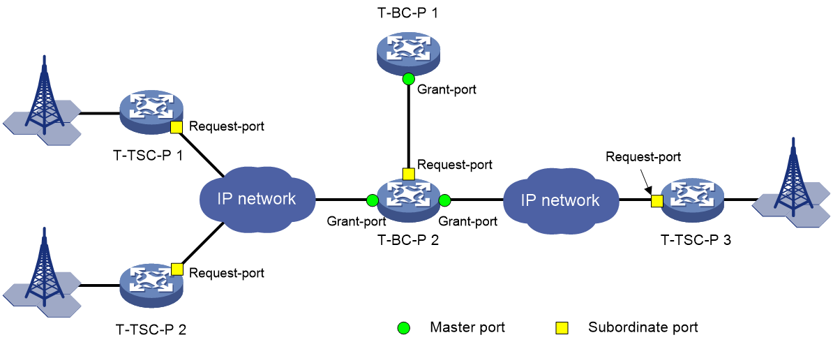
· Partial-support telecom boundary clock (T-BC-P)—A clock node with more than one PTP port in a PTP domain for time synchronization. It uses one of the ports to synchronize time to its upstream clock node and uses the other ports to distribute time to the downstream clock nodes. When a T-BC-P clock node is a clock source, it distributes time through multiple PTP ports to its downstream clock nodes.
· Partial-support telecom time slave clock (T-TSC-P)—A clock node with a single PTP port in a PTP domain for time synchronization. It synchronizes time from its upstream clock node through the port. It can operate only as a member clock.
Figure 3 shows the positions of these basic clock nodes in a PTP domain.
Figure 3 Clock nodes and PTP ports in a PTP domain (ITU-T G.8275.2)
Technical standard
A PTP profile uses the parameters including time accuracy, time class, time source, and clock offset (log variance) to describe PTP clock source signals. Users can customize and supplement a PTP profile based on the network conditions to develop their own PTP technical standard.
Three PTP technical standards are available: the default technical standard, OAM technical standard, and Unicom technical standard. The default parameter values, the elected clock source, and PTP message processing vary by technical standard.
Master-member/subordinate relationship
The master-member/subordinate relationship is automatically determined based on the Best Master Clock (BMC) algorithm. You can also manually specify a role for the clock nodes.
The master-member/subordinate relationship is defined as follows:
· Master/Member node—A master node sends a synchronization message, and a member node receives the synchronization message.
· Master/Member clock—The clock on a master node is a master clock (parent clock) The clock on a member node is a member clock.
· Master/Subordinate/Passive port—A master port sends a synchronization message, and a subordinate port receives the synchronization message. The master and subordinate ports can be on a BC or an OC. A port that neither receives nor sends synchronization messages is a passive port.
· Grant-port/request-port—A grant-port grants and provides PTP message service. A request-port requests and receives PTP message service. Typically, a grant-port is in master state. A request-port is in slave state when selected as the port for time synchronization and in listening state when not selected.
Clock source type
A clock node supports the following clock sources:
· Local clock source—38.88 MHz clock signals generated by a crystal oscillator inside the clock monitoring module.
· External clock source—Clock signals generated by an external clock device. The signals are received and sent by a 1PPS/ToD port on the MPU. It is also called a ToD clock source.
Grandmaster clock
As shown in Figure 1, the grandmaster clock (GM) is the ultimate source of time for clock synchronization in a PTP domain. It is elected automatically by the clock nodes in the PTP domain. The clock nodes exchange PTP messages and elect the GM by comparing the clock priority, time class, and time accuracy carried in the PTP messages.
You can also specify a GM manually.
Grandmaster clock selection and master-member/subordinate relationship establishment
IEEE 1588 version 2
A GM can be manually specified. It can also be automatically elected through the BMC algorithm as follows:
1. The clock nodes in a PTP domain exchange announce messages and elect a GM by using the following rules in descending order of precedence:
a. Clock node with higher priority 1.
b. Clock node with higher time class.
c. Clock node with higher time accuracy.
d. Clock node with higher priority 2.
e. Clock node with a smaller port ID (containing clock number and port number).
The master nodes, member nodes, master ports, and subordinate ports are determined during the process. Then a spanning tree with the GM as the root is generated for the PTP domain.
2. The master node periodically sends announce messages to the member nodes. If the member nodes do not receive announce messages from the master node, they determine that the master node is invalid, and they start to elect another GM.
ITU-T G.8275.1
A GM can be manually specified. It can also be automatically elected through the BMC algorithm as follows:
1. The clock nodes in a PTP domain exchange announce messages and elect a GM by using the following rules in descending order of precedence:
a. Clock node with higher time class.
b. Clock node with higher time accuracy.
c. Clock node with higher priority 2.
d. Clock node with higher local priority.
You can use the ptp priority clock-source command to set the local priority for the local node.
To set a local priority for the peer node, use the ptp local-priority command to set a local priority for the PTP interface connected to the peer node. This priority will be used as the local priority of the peer node.
e. Whether the time class values of the clock nodes are smaller than or equal to 127.
- If the time class values of the clock nodes are smaller than or equal to 127, two or more clock nodes are elected GMs in the PTP domain. A member node selects the GM nearer to it as its master node. Two or more spanning trees are generated. No PTP messages are exchanged between the trees.
- If the time class values of the clock nodes are greater than 127, the clock node with a smaller port ID (containing clock number and port number) will be the GM.
The master nodes, member nodes, master ports, and subordinate ports are determined during the process.
2. The master node periodically sends announce messages to the member nodes. If the member nodes do not receive announce messages from the master node, they determine that the master node is invalid, and they start to elect another GM.
ITU-T G.8275.2
This profile allows using two approaches to establish a synchronization tree.
· Specifying the grant-ports and request-ports—The request-ports request announce messages from a specific grant-port and the grant-port grants and provides announce messages to the request-ports, to quickly determine the GM. Plan in advance to ensure that the device where the grant-port resides has the best clock source. If the device does not have the best clock source, the request-ports will be in listening state, resulting in time synchronization failure.
· Dynamic election—All clock ports exchange announce messages to elect the GM and establish a synchronization tree.
In a PTP domain, use the same approach on the clock nodes to establish a synchronization tree as a best practice. If you apply the two approaches on the same device, both the announce messages requested by the request-port and received during dynamic election participate in Alternate BMC calculation for GM election. As a result, the request-ports might not be selected as the ports for clock synchronization.
Synchronization mechanism
After master-member relationships are established between the clock nodes, the master and member clock nodes exchange PTP messages and record the message transmit and receive time. Based on the timestamps, each member clock calculates the path delay and time offset between them and the master clock and adjusts their time accordingly for time synchronization with the master clock.
PTP defines two path delay measurement mechanisms: Request_Response_ and Peer Delay, both of which are based on network symmetry.
Request_Response
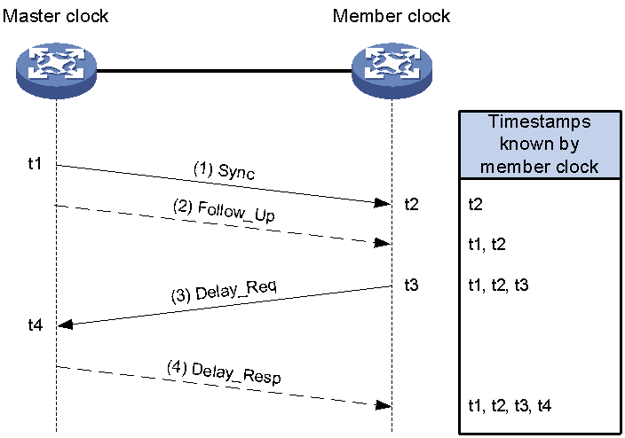
The Request_Response mechanism measures the average path delay between the master and member clock nodes by using the PTP messages as shown in Figure 4. A TC between master and member clock nodes does not calculate the path delay. It forwards PTP messages and makes residence time correction on the Sync messages.
This mechanism can be implemented in one of the following two modes:
· Two-step mode—t1 is carried in the Follow_Up message as shown in Figure 4.
· Single-step mode—t1 is carried in the Sync message, and no Follow_Up message is sent.
Figure 4 shows the Request_Response mechanism in two-step mode.
1. The master clock sends a Sync message to the member clock, and records the sending time t1. Upon receiving the message, the member clock records the receiving time t2.
2. After sending the Sync message, the master clock immediately sends a Follow_Up message that carries time t1.
3. The member clock sends a Delay_Req message to the master clock, and records the sending time t3. Upon receiving the message, the master clock records the receiving time t4.
4. The master clock returns a Delay_Resp message that carries time t4.
After this procedure, the member clock obtains all the four timestamps and can make the following calculations:
· Round-trip delay between the master and member clocks: (t2 – t1) + (t4 – t3)
· One-way delay between the master and member clocks: [(t2 – t1) + (t4 – t3)] / 2
· Offset between the member and master clocks: (t2 – t1) – [(t2 – t1) + (t4 – t3)] / 2 or [(t2 – t1) – (t4 – t3)] / 2
Figure 4 Request_Response mechanism (two-step node)
Peer Delay
The Peer Delay mechanism measures the average path delay between two clock nodes by using Pdelay messages. The two clock nodes (BC, TC, or OC) using this mechanism send Pdelay messages to each other, and calculate the one-way link delay between them independently. The message interaction process and delay calculation method are identical on the two nodes. TCs that exist between master and member clock nodes divide the synchronization path into multiple links. Each TC makes link delay and residence time corrections on the Sync messages.
This mechanism can be implemented in one of the following two modes:
· Two-step mode
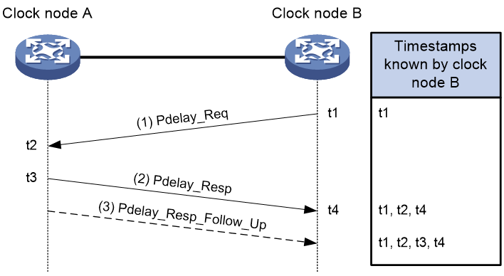
As shown in Figure 5, Pdelay messages include Pdelay_Req, Pdelay_Resp, and Pdelay_Resp_Follow_Up messages. t2 is carried in the Pdelay_Resp message, and t3 is carried in the Pdelay_Resp_Follow_Up message.
· Single-step mode:
Pdelay messages include Pdelay_Req and Pdelay_Resp messages. t3 – t2 is carried in the Pdelay_Resp, and no Pdelay_Resp_Follow_Up message is sent.
Figure 5 uses Clock node B as an example to describe the Peer Delay mechanism.
1. Clock node B sends a Pdelay_Req message to Clock node A, and records the sending time t1. Upon receiving the message, Clock node A records the receiving time t2.
2. Clock node A sends a Pdelay_Req message that carries t2 to Clock node B, and records the sending time t3. Upon receiving the message, Clock node B records the receiving time t4.
3. Clock node A immediately sends a Pdelay_Resp_Follow_Up message carrying t3 to Clock node B after sending the Pdelay_Req message.
After this procedure, Clock node B obtains all the four timestamps and can make the following calculations:
· Round-trip delay between Clock node A and Clock node B: (t2 – t1) + (t4 – t3)
· One-way delay between Clock node A and Clock node B: [(t2 – t1) + (t4 – t3)] / 2 = [(t4 – t1) – (t3 – t2)] / 2
· Time offset between the member clock and the master clock: Sync message receiving time on the member clock – Sync message sending time on the master clock – Total one-way delays on all links – Total PTP message residence time on all TCs.
Figure 5 Peer Delay mechanism (two-step mode)
Protocols and standards
· IEEE Std 1588-2008, IEEE Standard for a Precision Clock Synchronization Protocol for Networked Measurement and Control Systems, 2008
· ITU-T G.8275.1, Precision time protocol telecom profile for phase/time synchronization with full timing support from the network
· ITU-T G.8275.2, Precision time protocol telecom profile for phase/time synchronization with partial timing support from the network
Restrictions and guidelines: PTP configuration
A subcard interface operating in WAN mode does not support PTP. For more information about WAN mode, see Ethernet interface configuration in Interface Configuration Guide.
Only these interfaces on the following subcards and cards support PTP:
· 1000 Mbps optical interfaces on the following subcards:
¡ NIC-GP24L1
¡ NIC-GP24L1A
¡ MIC-GP10L-V2
¡ MIC-GP20L
· 10 Gbps interfaces on the following subcards:
¡ RX-NIC-XP5L
¡ RX-NIC-XP10L
¡ RX-NIC-XP20L
¡ NIC-XP5L
¡ NIC-XP10L
¡ NIC-XP20L
· 10 Gbps interface operating in LAN mode on the following subcards:
¡ NIC-XP20L1
· 10 Gbps and 25 Gbps interfaces on the following subcards:
¡ RX-NIC-YGS4L
· 50 Gbps interfaces on the following subcards:
¡ RX-NIC-LGQ2L
¡ RX-NIC-LGQ4L
¡ NIC-LGQ2L
¡ NIC-LGQ4L
· 100 Gbps interfaces on the following subcards:
¡ RX-NIC-CC1L
¡ RX-NIC-CC2L
¡ RX-NIC-CQ1LF
¡ RX-NIC-CQ2LF
¡ NIC-CC1L
¡ NIC-CC2L
¡ NIC-CQ1L
¡ NIC-CQ2L
· 10 Gbps interfaces on the CEPC-XP48RX card.
· 10 Gbps interfaces operating in LAN mode on the CEPC-XP24LX card
· 1000 Mbps interfaces on the following subcards:
¡ MIC-GP20L
· 10 Gbps interfaces operating in LAN mode on the following subcards:
¡ MIC-XP2L
¡ MIC-XP2L-LAN
¡ MIC-XP4L1
¡ MIC-XP5L
¡ MIC-XP5L1
¡ MIC-XP8L
¡ MIC-XP20L
For information about LAN/WAN switching, see Ethernet interface configuration in Interface Configuration Guide.
· 100 Gbps interfaces on the following subcards:
¡ MIC-CQ2L
¡ MIC-CP1L
· Interfaces on the following cards:
¡ CSPEX-1304X
¡ CSPEX-1404X
¡ CSPEX-1502X
¡ CSPEX-1504X
¡ CSPEX-1504XA
¡ CSPEX-1602X
¡ CSPEX-1602XA
¡ CSPEX-1512X
¡ CSPEX-1612X
¡ CSPEX-1812X
¡ RX-SPE200
¡ CEPC-XP4LX
¡ CEPC-XP24LX
¡ CEPC-XP48RX
¡ CEPC-CP4RX
¡ CEPC-CP4RXA
¡ CEPC-CP4RX-L
¡ CSPEX-1802X
¡ CSPEX-1802XA
¡ CSPEX-1812X-E
¡ CSPEX-2304X-G
¡ CEPC-CQ8L
¡ CEPC-CQ8LA
¡ CEPC-CQ16L1
¡ CSPEX-1502XA
¡ RX-SPE200-E
For PTP to function correctly, make sure the device is installed with the CSR05SRP1L3, CSR05SRP1R3, CSR05SRP1P3, or CSR05SRP1P3-G MPU.
If copper-to-fiber conversion modules are used on the PTP network, use PTP for time and frequency synchronization. Do not use synchronous Ethernet for frequency synchronization.
Before configuring PTP, determine the PTP standard and define the scope of the PTP domain and the role of every clock node.
In a PTP domain that runs the IEEE 1588 version 2 PTP profile, specify the BC or OC clock node type for the devices in the domain as a best practice. A TC clock node is mainly used for forwarding PTP messages. When receiving a PTP message, a TC multicasts the message from all its PTP interfaces except the inbound interface of the PTP message. To deploy a TC in the domain, plan the TC location and number and location of PTP interfaces on the TC manually to prevent PTP forwarding loops.
PTP tasks at a glance
Configuring PTP (IEEE 1588 version 2)
1. Specifying PTP for obtaining the time
Specify the IEEE 1588 version 2 PTP profile.
¡ Specifying a clock node type
¡ (Optional.) Configuring an OC to operate only as a member clock
4. (Optional.) Specifying a PTP domain
5. (Optional.) Enabling the PTP clock state feature
¡ (Optional.) Configuring the role of a PTP port
¡ Configuring the mode for carrying timestamps
¡ Specifying a delay measurement mechanism
¡ Configuring one of the ports on a TC+OC clock as an OC-type port
8. (Optional.) Configuring PTP message transmission and receiving
¡ Setting the interval for sending Pdelay_Req messages
¡ Setting the interval for sending Sync messages
¡ Setting the minimum interval for sending Delay_Req messages
9. (Optional.) Configuring parameters for PTP messages
¡ Specifying the IPv4 UDP transport protocol for PTP messages
¡ Configuring a source IP address for multicast
¡ Configuring a destination IP address for unicast
¡ Configuring the destination MAC address for PTP messages
¡ Setting a DSCP value for PTP messages transmitted over
¡ Specifying a VLAN tag for PTP messages
10. (Optional.) Disabling PTP path tracing
11. (Optional.) Specifying the maximum number of removed steps (clock nodes) from the GM to the device
12. (Optional.) Enabling the device to notify the downstream nodes of its time synchronization state
13. (Optional.) Adjusting and correcting clock synchronization
¡ Setting the delay correction value
¡ Calculating the TAI based on the UTC time
¡ Configuring ToD input or output
¡ Enabling the device to ignore the synchronizationUncertain flag
(Optional.)
1.
2. (Optional.) Configuring a priority for a clock (IEEE 1588 version 2)
3. (Optional.) Configuring PTP logging
Configuring PTP (ITU-T G.8275.1)
1. Specifying PTP for obtaining the time
Specify the IEEE 802.1AS PTP profile.
3. Specifying a clock node type
4. (Optional.) Specifying a PTP domain
5. (Optional.) Specifying a PTP technical standard
6. (Optional.) Enabling the PTP clock state feature
¡ (Optional.) Configuring the role of a PTP port
¡ Configuring the mode for carrying timestamps
9. (Optional.) Configuring PTP message transmission and receiving
¡ Setting the interval for sending Sync messages
¡ Setting the minimum interval for sending Delay_Req messages
10. (Optional.) Configuring parameters for PTP messages
¡ Configuring the destination MAC address for PTP messages
¡ Specifying a VLAN tag for PTP messages
11. (Optional.) Disabling PTP path tracing
12. (Optional.) Specifying the maximum number of removed steps (clock nodes) from the GM to the device
13. (Optional.) Enabling the device to notify the downstream nodes of its time synchronization state
14. (Optional.) Adjusting and correcting clock synchronization
¡ Setting the delay correction value
¡ Calculating the TAI based on the UTC time
¡ Configuring ToD input or output
¡ Enabling the device to ignore the synchronizationUncertain flag
(Optional.)
1.
2. (Optional.) Configuring a priority for a clock (ITU-T G.8275.1 and ITU-T G.8275.2)
3. (Optional.) Configuring PTP logging
Configuring PTP (ITU-T G.8275.2)
1. Specifying PTP for obtaining the time
Specify the ITU-T G.8275.2 PTP profile.
3. Specifying a clock node type
4. (Optional.) Specifying a PTP domain
¡ (Optional.) Configuring the role of a PTP port
¡ Configuring the mode for carrying timestamps
¡ Enabling unicast negotiation on PTP ports
7. Configuring PTP message transmission and receiving
¡ Setting the interval for sending Sync messages
¡ Setting the minimum interval for sending Delay_Req messages
¡ Setting the interval for sending Delay-Resp messages
8. (Optional.) Configuring parameters for PTP messages
¡ Configuring the destination MAC address for PTP messages
¡ Specifying a VLAN tag for PTP messages
9. (Optional.) Disabling PTP path tracing
10. (Optional.) Specifying the maximum number of removed steps (clock nodes) from the GM to the device
11. (Optional.) Adjusting and correcting clock synchronization
¡ Setting the delay correction value
¡ Calculating the TAI based on the UTC time
¡ Configuring ToD input or output
12. (Optional.) Configuring a priority for a clock (IEEE 1588 version 2)
13. (Optional.) Configuring PTP logging
Specifying PTP for obtaining the time
1. Enter system view.
system-view
2. Specify PTP for obtaining the time.
clock protocol ptp mdc 1
By default, the device uses NTP to synchronize the system time.
For more information about the clock protocol command, see device management commands in Fundamentals Command Reference.
Specifying a PTP profile
Restrictions and guidelines
You must specify a PTP profile before configuring PTP settings. Changing the PTP profile clears all settings under the profile.
Procedure
1. Enter system view.
system-view
2. Specify a PTP profile.
ptp profile { 1588v2 | g8275.1 | g8275.2 }
By default, no PTP profile is specified for the device.
Configuring clock nodes
Specifying a clock node type
Restrictions and guidelines
Before you specify a clock node type, specify a PTP profile.
Changing or removing the clock node type restores the default settings of the PTP profile.
Procedure
1. Enter system view.
system-view
2. Specify a clock node type.
IEEE 1588v2 PTP profile:
ptp mode { bc | e2etc | e2etc-oc | oc | p2ptc | p2ptc-oc }
ITU-T G.8275.1 PTP profile:
ptp mode { t-bc | t-tc | t-tsc }
ITU-T G.8275.2 PTP profile:
ptp mode { t-bc-p | t-tsc-p }
By default, no clock node type is specified.
Configuring an OC to operate only as a member clock
About this task
An OC can operate either as a master clock to send synchronization messages or as a member clock to receive synchronization messages. This task allows you to configure an OC to operate only as a member clock.
If an OC is operating only as a member clock, you can use the ptp force-state command to configure its PTP port as a master port or passive port.
Restrictions and guidelines
This task is applicable only to OCs.
Procedure
1. Enter system view.
system-view
2. Configure the OC to operate only as a member clock.
ptp slave-only
By default, an OC operates as a master or member clock.
Specifying a PTP domain
About this task
Within a PTP domain, all devices follow the same rules to communicate with each other. Devices in different PTP domains cannot exchange PTP messages.
Procedure
1. Enter system view.
system-view
2. Specify a PTP domain for the device.
ptp domain value
The default settings of this command depends on the PTP profile.
¡ The device is in PTP domain 0 when the PTP profile is IEEE 1588 version 2.
¡ The device is in PTP domain 24 when the PTP profile is ITU-T G.8275.1.
¡ The device is in PTP domain 44 when the PTP profile is ITU-T G.8275.2.
Specifying a PTP technical standard
Restrictions and guidelines
This task is available only for the ITU-T G.8275.1 PTP profile.
The ptp technical-standard command is mutually exclusive with the ptp clock-state enable command.
Procedure
1. Enter system view.
system-view
2. Specify a PTP technical standard.
ptp technical-standard { oam | unicom }
By default, the default PTP technical standard applies.
Enabling the PTP clock state feature
About this task
The PTP clock state feature defines and clarifies the following PTP clock states:
· Free-Run—The PTP clock has never been synchronized to a time source and is not in the process of synchronizing to a time source.
· Acquiring—The PTP clock is in the process of synchronizing to a time source.
· Locked—The PTP clock has been synchronized to a time source within the acceptable accuracy.
· Holdover—The PTP clock is no longer synchronized to a time source and is using information obtained when it was previously synchronized.
Restrictions and guidelines
This task is available only for the IEEE 1588 version 2 and ITU-T G.8275.1 PTP profiles.
The ptp technical-standard command is mutually exclusive with the ptp clock-state enable command.
Procedure
1. Enter system view.
system-view
2. Enable the PTP clock state feature.
ptp technical-standard { oam | unicom }
By default, the PTP clock state feature is disabled.
Enabling PTP on a port
About this task
A port enabled with PTP becomes a PTP port.
Restrictions and guidelines
You can enable PTP on only one port on an OC, T-TSC, or T-TSC-P clock node.
To enable PTP on a Layer 3 Ethernet interface that has been assigned to a VPN instance, you must specify this VPN instance in the ptp source ip-address vpn-instance vpn-instance-name command if PTP messages are to be transmitted in multicast mode over IPv4 UDP.
Procedure
1. Enter system view.
system-view
2. Enter Layer 2 Ethernet interface view, Layer 3 Ethernet interface view, or FlexE physical interface view.
interface interface-type interface-number
3. Enable PTP on the port.
ptp enable
By default, PTP is disabled on a port.
Configuring PTP ports
Configuring the role of a PTP port
About this task
You can configure the master, passive, or slave role for a PTP port.
For an OC that operates in slave-only mode, you can perform this task to change its PTP port role to master or slave.
Restrictions and guidelines
By default, the PTP port roles are automatically negotiated based on the BMC algorithm. If you use the ptp force-state command to change the role of one PTP port, all the other PTP ports in the PTP domain stop working. For these PTP ports to function, you must specify roles for each of them by using the ptp force-state command. As a best practice, enable automatic negotiation of PTP port roles based on the BMC algorithm.
You can configure only one subordinate port on a device.
After you change the role of a PTP port, you must execute the ptp active force-state command to activate the port role configuration.
This task is not available for a T-TSC, T-TSC-P, or T-BC-P clock node.
Procedure
1. Enter system view.
system-view
Enter Layer 2 Ethernet interface view, Layer 3 Ethernet interface view, or FlexE physical interface view.
interface interface-type interface-number
2. Configure the role of the PTP port.
ptp force-state { master | passive | slave }
By default, the PTP port role is automatically calculated through BMC.
3. Return to system view.
quit
4. Activate the port role configuration.
ptp active force-state
By default, the port role configuration is not activated.
Configuring the mode for carrying timestamps
About this task
Timestamps can be carried in either of the following modes:
· Single-step mode—The Sync message (in the Request_Response or Peer Delay mechanism) and Pdelay_Resp message (in the Peer Delay mechanism) carry their sending timestamps by themselves.
· Two-step mode—The Sync message (in the Request_Response or Peer Delay mechanism) and Pdelay_Resp message (in the Peer Delay mechanism) do not carry their sending timestamps by themselves. The subsequent messages carry their sending timestamps.
Restrictions and guidelines
When the device is configured as a TC, follow these restrictions and guidelines:
· Configure the same timestamp-carrying mode for the interface receiving PTP messages and interface transmitting PTP messages.
· If subcards in column A are used together with subcards in column B together on the TC, configure the two-step timestamp carrying mode for the interface receiving PTP messages and interface transmitting PTP messages.
|
A |
B |
|
· RX-NIC-LGQ2L · RX-NIC-LGQ4L · RX-NIC-YGS4L · RX-NIC-CQ1LF · RX-NIC-CQ2LF · NIC-LGQ2L · NIC-LGQ4L · NIC-XP20L1 |
· RX-NIC-CC1L · RX-NIC-CC2L · RX-NIC-XP5L · RX-NIC-XP10L · RX-NIC-XP20L · NIC-XP5L · NIC-XP10L · NIC-XP20L · NIC-CC1L · NIC-CC2L · NIC-CQ1L · NIC-CQ2L |
The interfaces on the RX-NIC-LGQ4L, RX-NIC-CQ1LF, RX-NIC-CQ2LF, and RX-NIC-LGQ2L subcards support one-step timestamp carrying mode only when they are working in Ethernet mode. For information about Ethernet mode, see device management configuration in Fundamentals Configuration Guide.
The interfaces on the MIC-GP10L-V2, MIC-GT20L, MIC-CQ1L1, and NIC-XP20L1 subcards support only the two-step timestamp carrying mode.
Procedure
1. Enter system view.
system-view
2. Enter Layer 2 Ethernet interface view, Layer 3 Ethernet interface view, or FlexE physical interface view.
interface interface-type interface-number
3. Configure the mode for carrying timestamps.
ptp clock-step { one-step | two-step }
By default, two-step mode is used for carrying timestamps.
Specifying a delay measurement mechanism
Restrictions and guidelines
PTP defines two transmission delay measurement mechanisms: Request_Response and Peer Delay. For correct communication, ports on the same link must share the same delay measurement mechanism.
When the PTP profile is IEEE 1588 version 2, the following restrictions apply:
· This task is available only for a BC or OC clock node.
· This task is not available for an E2ETC, E2ETC+OC, P2PTC, or P2PTC+OC clock node. The E2ETC and E2ETC+OC clock nodes support both request-response and peer delay measurement mechanisms. A P2PTC clock node supports only the peer delay measurement mechanism.
The ITU-T G.8275.1 PTP profile supports only the request-response delay measurement mechanism and does not support this task.
The ITU-T G.8275.2 PTP profile supports only the request-response delay measurement mechanism and does not support this task.
Procedure
1. Enter system view.
system-view
2. Enter Layer 2 Ethernet interface view, Layer 3 Ethernet interface view, or FlexE physical interface view.
interface interface-type interface-number
3. Specify a delay measurement mechanism.
ptp delay-mechanism { e2e | p2p }
The e2e keyword specifies the Request_Response mechanism, and the p2p keyword specifies the Peer Delay mechanism.
The default delay measurement mechanism depends on the PTP profile.
¡ When the PTP profile is IEEE 1588 version 2, the request-response delay measurement mechanism applies.
¡ When the PTP profile is ITU-T G.8275.1, the request-response delay measurement mechanism applies.
¡ When the PTP profile is ITU-T G.8275.2, the request-response delay measurement mechanism applies.
Configuring one of the ports on a TC+OC clock as an OC-type port
About this task
All ports on a TC+OC (E2ETC+OC or P2PTC+OC) are TC-type ports by default. This feature allows you to configure one of the ports on a TC+OC clock as an OC-type port.
Restrictions and guidelines
This task is applicable only to E2ETC+OCs and P2PTC+OCs.
For time synchronization accuracy, the OC-type port on an E2ETC+OC or P2PTC+OC must be specified as the master port.
This task is not available under the ITU-T G.8275.1 or ITU-T G.8275.2 PTP profile.
Procedure
1. Enter system view.
system-view
2. Enter Layer 2 Ethernet interface view, Layer 3 Ethernet interface view, or FlexE physical interface view.
interface interface-type interface-number
3. Configure the port type as OC.
ptp port-mode oc
By default, the port type for all ports on a TC+OC is TC.
Enabling NotSlave on a PTP port
About this task
The NotSlave feature, supported only by the ITU-T G.8275.1 and ITU-T G.8275.2 PTP profiles, enables a PTP port to select the clock node where it resides as the master node. You can use this feature to control master/member role of the clock nodes. For automatic master/member clock node selection in a PTP domain under the ITU-T G.8275.1 or ITU-T G.8275.2 PTP profile, you must disable NotSlave on all PTP ports.
Restrictions and guidelines
Only the ITU-T G.8275.1 and ITU-T G.8275.2 PTP profiles support this task.
· When the PTP profile is ITU-T G.8275.1, you can configure this task only on a T-BC or T-TC clock node.
· When the PTP profile is ITU-T G.8275.1, you can configure this task only on a T-BC-P clock node.
Procedure
1. Enter system view.
system-view
2. Enter Layer 2 Ethernet interface view, Layer 3 Ethernet interface view, or FlexE physical interface view.
interface interface-type interface-number
3. Disable NotSlave.
ptp notslave disable.
Enabling unicast negotiation on PTP ports
About this task
The ITU-T G.8275.2 PTP profile allows establishing a PTP synchronization tree by specifying the request-ports and master-ports.
A request-port initiates a connection request to a specific grant-port. Then they negotiate PTP parameters and exchange PTP messages to synchronize the client time to the server. Plan the network in advance and specify the ports on the member (client) clock nodes as request-ports and the ports on the master (server) clock nodes as grant-ports.
Restrictions and guidelines
Only the ITU-T G.8275.2 PTP profile supports this task.
Procedure
1. Enter system view.
system-view
2. Enter Layer 3 Ethernet interface view.
interface interface-type interface-number
3. Enable unicast negotiation and specify the port as a grant-port or request port.
ptp unicast-negotiate { grant-port | request-port }
Configuring PTP message transmission and receiving
Setting the interval for sending announce messages and the timeout multiplier for receiving announce messages
About this task
A master node periodically sends announce messages at the specified interval. If a member node does not receive any announce message from the master node after the timeout expires, it determines that the master node is invalid. The timeout = timeout multiplier × interval at which the master node sends announce messages.
The configuration of the interval at which the master node sends announce messages depends on the PTP profile in the PTP domain.
· PTP profile other than ITU-T G.8275.2, or ITU-T G.8275.2 PTP profile not using unicast negotiation—You must configure the interval on the master node.
· ITU-T G.8275.2 PTP profile using unicast negotiation—You must configure the interval on the request-port of the client. The request-port uses the configured interval to negotiate with the grant-port on the server for the interval at which the grant-port sends announce messages to the client. If the negotiation succeeds, the grant-port sends announce messages at the configured interval to the client. If the negotiation fails, the grant-port does not send announce messages to the client.
Procedure
1. Enter system view.
system-view
2. Enter Layer 2 Ethernet interface view, Layer 3 Ethernet interface view, or FlexE physical interface view.
interface interface-type interface-number
3. Set the interval for sending announce messages.
ptp announce-interval interval
The default varies by PTP profile:
¡ IEEE 1588 version 2—The interval argument value is 1 and the interval for sending announce messages is 2 (21) seconds.
¡ ITU-T G.8275.1 or ITU-T G.8275.2—The interval argument value is –3 and the interval for sending announce messages is 1/8 (2-3) seconds.
4. Set the number of intervals before a timeout occurs.
ptp announce-timeout multiple-value
By default, a timeout occurs when three intervals are reached.
The ITU-T G.8275.2 PTP profile does not support this command.
Setting the interval for sending Pdelay_Req messages
Restrictions and guidelines
This task is not available under the ITU-T G.8275.1 or ITU-T G.8275.2 PTP profile.
Procedure
1. Enter system view.
system-view
2. Enter Layer 2 Ethernet interface view, Layer 3 Ethernet interface view, or FlexE physical interface view.
interface interface-type interface-number
3. Set the interval for sending Pdelay_Req messages.
ptp pdelay-req-interval interval
By default, the interval argument value is 0 and the interval for sending peer delay request messages is 1 (20) second.
Setting the interval for sending Sync messages
About this task
This task allows you to configure the interval at which the master node sends Sync messages to the member nodes. The configuration of the interval depends on the PTP profile in the PTP domain.
· PTP profile other than ITU-T G.8275.2, or ITU-T G.8275.2 PTP profile not using unicast negotiation—You must configure this task on the master node.
· ITU-T G.8275.2 PTP profile using unicast negotiation—You must configure this task on the request-port of the client. The request-port uses the configured interval to negotiate with the grant-port on the server for the interval at which the grant-port sends Sync messages to the client. If the negotiation succeeds, the grant-port sends Sync messages at the configured interval to the client. If the negotiation fails, the grant-port does not send Sync messages to the client.
Procedure
1. Enter system view.
system-view
2. Enter Layer 2 Ethernet interface view, Layer 3 Ethernet interface view, or FlexE physical interface view.
interface interface-type interface-number
3. Set the interval for sending Sync messages.
ptp syn-interval interval
The default varies by PTP profile:
¡ IEEE 1588 version 2—The interval argument value is 0 and the interval for sending Sync messages is 1 (20) second.
¡ ITU-T G.8275.1 or ITU-T G.8275.2—The interval argument value is –4 and the interval for sending Sync messages is 1/16 (2-4) seconds.
Setting the minimum interval for sending Delay_Req messages
About this task
When receiving a Sync or Follow_Up message, an interface can send Delay_Req messages only when the minimum interval is reached.
Restrictions and guidelines
In PTP multicast transport mode, this setting takes effect only when configured on the master clock. The master clock sends the value to a member clock through PTP messages to control the interval for the member clock to send Delay_Req messages. To view the value on a member clock, execute the display ptp interface command on the member clock.
In PTP unicast transport mode, this setting takes effect when configured on member clocks. It does not take effect when configured on the master clock.
Procedure
1. Enter system view.
system-view
2. Enter Layer 2 Ethernet interface view, Layer 3 Ethernet interface view, or FlexE physical interface view.
interface interface-type interface-number
3. Set the minimum interval for sending Delay_Req messages.
ptp min-delayreq-interval interval
The default setting varies by PTP profile.
¡ IEEE 1588 version 2—The value of the interval argument is 0 and the minimum interval for sending delay request messages is 1 (20) second.
¡ ITU-T G.8275.1—The value of the interval argument is –4 and the minimum interval for sending delay request messages is 1/16 (2-4) seconds.
¡ ITU-T G.8275.2—The value of the interval argument is –4 and the minimum interval for sending delay request messages is 1/16 (2-4) seconds.
Setting the interval for sending Delay-Resp messages
About this task
This task, configured on a request-port, specifies the interval at which the grant-port sends Delay_resp messages to the request-port. After receiving a Delay_req message from a request port, the grant-port responds by sending a Delay_resp message and starts a timer defined by this command. The grant-port will not send another Delay_resp message until it receives a Delay_req message after the timer expires.
Restrictions and guidelines
This task is available only for the ITU-T G.8275.2 PTP profile and is configured on request-ports.
Procedure
1. Enter system view.
system-view
2. Enter Layer 2 Ethernet interface view, Layer 3 Ethernet interface view, or FlexE physical interface view.
interface interface-type interface-number
3. Set the interval for sending Delay_resp messages.
ptp delay-resp-interval interval
By default, the value of the interval argument is –4 and the minimum interval for sending Delay_resp messages is 1/16 (2-4) seconds.
Configuring parameters for PTP messages
Specifying the IPv4 UDP transport protocol for PTP messages
About this task
PTP messages can be transported over IEEE 802.3/Ethernet or IPv4 UDP.
Restrictions and guidelines
The ITU-T G.8275.1 PTP profile supports only IEEE 802.3/Ethernet transport of PTP messages and do not support this task.
The ITU-T G.8275.2 PTP profile supports only IPv4 UDP transport of PTP messages and does not support this task.
Procedure
1. Enter system view.
system-view
2. Enter Layer 2 Ethernet interface view, Layer 3 Ethernet interface view, or FlexE physical interface view.
interface interface-type interface-number
3. Specify the IPv4 UDP transport protocol for PTP messages.
ptp transport-protocol udp
By default, PTP messages are transported over IEEE 802.3/Ethernet.
Configuring a source IP address for multicast PTP messages transmitted over IPv4 UDP
About this task
To transport multicast PTP messages over IPv4 UDP, you must configure a source IP address for the messages.
Restrictions and guidelines
If a source IP address for multicast PTP messages transmitted over IPv4 UDP and a destination address for unicast PTP messages transmitted over IPv4 UDP are both configured, the system unicasts the messages.
This task is not available under the ITU-T G.8275.1 or ITU-T G.8275.2 PTP profile
Procedure
1. Enter system view.
system-view
2. Configure a source IP address for multicast PTP messages transmitted over IPv4 UDP.
ptp source ip-address [ vpn-instance vpn-instance-name ]
By default, no source IP address is configured for multicast PTP messages transmitted over IPv4 UDP.
Configuring a destination IP address for unicast PTP messages transmitted over IPv4 UDP
About this task
Both unicast and multicast PTP messages can be transmitted over IPv4 UDP.
The destination IP address for multicast PTP messages transmitted over IPv4 UDP is 224.0.1.129 or 224.0.0.107, which cannot be modified. 224.0.1.129 and 224.0.0.107 are the destination IP addresses for messages in the Request_Response and Peer Delay mechanism, respectively.
To transmit unicast PTP messages over IPv4 UDP, you must configure a destination IP address for the messages.
Restrictions and guidelines
If a source IP address for multicast PTP messages transmitted over IPv4 UDP and a destination address for unicast PTP messages transmitted over IPv4 UDP are both configured, the system unicasts the messages.
This task is not available under the ITU-T G.8275.1 PTP profile
You must configure this task when the PTP profile is ITU-T G.8275.2.
Prerequisites
Configure an IP address for the current interface, and make sure the interface and the peer PTP interface can reach each other.
Procedure
1. Enter system view.
system-view
2. Enter Layer 3 Ethernet interface view
interface interface-type interface-number
3. Configure a destination IP address for unicast PTP messages transmitted over IPv4 UDP.
ptp unicast-destination ip-address
By default, no destination IP address is configured for unicast PTP messages transmitted over IPv4 UDP.
Configuring the destination MAC address for PTP messages
About this task
IEEE 802.3/Ethernet-encapsulated PTP messages can be sent through multicast or unicast. The destination MAC address for PTP messages can be as follows:
· Any unicast MAC address in unicast mode.
· In multicast mode:
¡ 0180-C200-000E or 011B-1900-0000 for non-Pdelay messages, including delay_Req, delay_Resp, delay_Resp_Follow_Up, Announce, Sync, and FollowUp messages.
¡ 0180-C200-000E for Pdelay messages, including Pdelay_Req, Pdelay_Resp, and Pdelay_Resp_Follow_Up messages.
Restrictions and guidelines
You must specify the PTP profile and a PTP mode before configuring this feature.
This command is not available for the ITU-T G.8275.2 PTP profile.
This feature takes effect only when PTP messages are encapsulated in IEEE 802.3/Ethernet packets.
Procedure
1. Enter system view.
system-view
2. Enter Layer 2 Ethernet interface view, Layer 3 Ethernet interface view, or FlexE physical interface view.
interface interface-type interface-number
3. Configure the destination MAC address for PTP messages.
ptp destination-mac mac-address
By default, the destination MAC address for non-Pdelay messages is 011B-1900-0000 and the destination MAC address for Pdelay messages is 0180-C200-000E.
Setting a DSCP value for PTP messages transmitted over IPv4 UDP
About this task
The DSCP value determines the sending precedence of PTP messages transmitted over IPv4 UDP.
Restrictions and guidelines
This task is not available under the ITU-T G.8275.1 PTP profile.
When the PTP profile is ITU-T G.8275.2, set a DSCP value as high as possible to allow 1588v2 packets to reach the destination even when the network is congested.
Procedure
1. Enter system view.
system-view
2. Enter Layer 2 Ethernet interface view, Layer 3 Ethernet interface view, or FlexE physical interface view.
interface interface-type interface-number
3. Set a DSCP value for PTP messages transmitted over IPv4 UDP.
ptp dscp dscp
By default, the DSCP value is 56.
Specifying a VLAN tag for PTP messages
About this task
Perform this task to configure the VLAN ID and the 802.1p precedence in the VLAN tag carried by PTP messages.
Procedure
1. Enter system view.
system-view
2. Enter Layer 2 Ethernet interface view.
interface interface-type interface-number
3. Specify a VLAN tag for PTP messages.
ptp vlan vlan-id [ dot1p dot1p-value ]
By default, PTP messages do not have a VLAN tag.
Disabling PTP path tracing
About this task
PTP path tracing traces the clock nodes that the clock signals traverse from the GM to the device. The system can obtain complete path tracing information only when all clock nodes on the path are enabled with PTP path tracing. If a device on the path does not support PTP path tracing, disable this feature to prevent PTP intercommunication issues.
Procedure
1. Enter system view.
system-view
2. Disable PTP path tracing.
ptp path-trace disable
By default, PTP path tracing is enabled.
Specifying the maximum number of removed steps (clock nodes) from the GM to the device
About this task
If the number of removed steps from the GM to the device on the PTP synchronization path is too large, the time synchronization accuracy will decrease. After you specify the maximum number of removed steps from the GM to the device, the device cannot synchronize time through PTP if the number of the removed steps exceeds the maximum value.
Procedure
1. Enter system view.
system-view
2. Specify the maximum number of removed steps from the GM to the device.
ptp max-steps-removed step-removed-value
By default, the maximum number of removed steps from the GM to the device is 255.
Enabling the device to notify the downstream nodes of its time synchronization state
About this task
The task enables the device to notify its downstream nodes of its time synchronization state.
By default, the device transfers only the locked and unlocked status of the upstream node to the downstream nodes, and does not transfer its locked or unlocked status to the downstream nodes.
After this task is configured, the device notifies the downstream nodes of its locked and unlocked status through the synchronizationUncertain flag in the announce messages. The downstream nodes do not synchronize to the device when they receive information that the device time is unlocked and synchronize to the device when they receive information that the device time is locked.
Restrictions and guidelines
This task is available only for the IEEE 1588 version 2 and ITU-T G.8275.1 PTP profiles.
Procedure
1. Enter system view.
system-view
2. Enable the device to notify the downstream nodes of its time synchronization state.
ptp sync-uncertain enable
By default, the device does not notify the downstream nodes of its time synchronization state.
Adjusting and correcting clock synchronization
Setting the delay correction value
About this task
PTP performs time synchronization based on the assumption that the delays in sending and receiving messages are the same. However, this is not practical. If you know the offset between the delays in sending and receiving messages, you can set the delay correction value for more accurate time synchronization.
Procedure
1. Enter system view.
system-view
2. Enter Layer 2 Ethernet interface view, Layer 3 Ethernet interface view, or FlexE physical interface view.
interface interface-type interface-number
3. Set a delay correction value.
ptp asymmetry-correction { minus | plus } value
The default is 0 nanoseconds. Delay correction is not performed.
Calculating the TAI based on the UTC time
About this task
International Atomic Time (TAI) is a high-precision atomic coordinate time scale. Coordinated Universal Time (UTC) is based on TAI and adjusted by leap seconds for synchronization with astronomical time.
UTC is constantly compared with UT1 (astronomical time, reflecting the earth's rotation). The International Bureau of Weights and Measures (BIPM) will notify to add or subtract one second from the UTC time scale at the last minute on a specific date (typically June 30 or December 31) to ensure that the difference between UTC and UT1 is within one second.
The BIPM publishes the difference between UTC and TAI periodically. Till now, UTC is 37 seconds behind TAI.
Internet devices typically use the UTC time. To provide more accurate time, PTP also uses TAI. If the device acts as a subordinate clock node, it uses the UTC time and TAI time of the clock reference. If the device acts as the clock reference, it will calculate the TAI time based on the UTC time, and synchronize the UTC and TAI time to the subordinate clocks. This task is used to calculate the TAI time based on the UTC time.
TAI = UTC + cumulative offset. To get the correct TAI time from the UTC time:
· Set the accurate UTC time on the device.
· Use the ptp utc offset command to set the cumulative offset of UTC relative to TAI as published by BIPM. This command takes effect immediately.
· If the BIPM notifies to add or subtract one second from the UTC time scale on a specific data after you use the ptp utc offset command to configure the cumulative offset of TAI relative to UTC, use the ptp utc { leap59-date | leap61-date } date command to change the UTC time. The TAI time will be changed accordingly.
Restrictions and guidelines
This setting takes effect only when it is configured on the master clock node and the local clock of the master clock node is the GM.
Configure this feature on both the master and member nodes for the new master clock to provide accurate TAI time after a master/member node switchover.
Procedure
1. Enter system view.
system-view
2. Set the cumulative offset of UTC relative to TAI.
ptp utc offset utc-offset
The default is 0 seconds.
3. Add or subtract one second from the UTC time scale at the last minute on the specified date.
ptp utc { leap59-date | leap61-date } date
By default, no second is added or subtracted from the UTC time.
Configuring ToD input or output
About this task
To use a ToD clock, you must configure ToD input or output:
· ToD input—The device obtains clock signals from an external ToD clock and synchronizes ToD to all cards on the device.
· ToD output—The device operates as a ToD clock to synchronize ToD to other devices in the PTP network.
To implement more accurate time synchronization, you can specify a delay correction value.
Procedure
1. Enter system view.
system-view
2. Configure ToD input or output.
ptp { tod0 | tod1 } { input [ delay input-delay-time ] | output [ delay output-delay-time ] }
By default, whether to receive or transmit ToD clock signals is not configured.
ToD 0 can only receive clock signals, and ToD 1 can only transmit signals.
Enabling the device to ignore the synchronizationUncertain flag
About this task
By default, the device reads the value of the synchronizationUncertain flag in the announce message it receives.
· A synchronizationUncertain bit value of 1 indicates that synchronization information from the upstream node is unlocked.
· A synchronizationUncertain bit value of 0 indicates that synchronization information from the upstream node is locked.
If synchronization information from the upstream node is unlocked, the device will not use that information for time synchronization. Only if synchronization information from the upstream node is locked, the device uses that information for time synchronization.
Typically, you are not required to configure this command. If the upstream clock is very reliable, you can configure this command to enable the device to ignore the synchronizationUncertain flag. After this command is configured, the device will synchronize the time directly with synchronization information from the upstream clock without reading the synchronizationUncertain bit value.
Restrictions and guidelines
Only the IEEE 1588 version 2 and ITU-T G.8275.1 PTP profiles support this task.
Procedure
1. Enter system view.
system-view
2. Enable the device to ignore the synchronizationUncertain flag.
ptp ignore sync-uncertain
By default, the device does not ignore the synchronizationUncertain flag.
Setting clock source parameters
Restrictions and guidelines
The clock's time class is an attribute of the device. For a local clock source, keep its default time class and do not modify it as a best practice.
Procedure
1. Enter system view.
system-view
2. Set clock source parameters. Choose the options to configure as needed:
¡ ptp clock-source local { accuracy acc-value | class class-value | time-source ts-value }
¡ ptp clock-source { tod0 | tod1 } { accuracy acc-value | class class-value | time-source ts-value | grandmaster-clockid clock-id | offsetscaled-logvariance value }
The default settings for clock source parameters vary by PTP profile and PTP technical standard.
· The clock ID of a GM clock is 000000-0000-000000.
· ITU-T G.8275.1 PTP profile
¡ T-TSC clock node type
- Local clock source—The accuracy value is 254, the time class value is 255, the offset (log variance) value is 65535, and the time source value is 160. The four values are fixed, not configurable.
- ToD clock source—The accuracy value is 254, the time class value is 255, the offset (log variance) value is 65535, and the time source value is 32.
¡ T-BC or T-TC clock node type
- Default PTP technical standard
Local clock source—The accuracy value is 254, the time class value is 248, the offset (log variance) value is 65535, and the time source value is 160. The offset (log variance) value is not configurable.
ToD clock source—The accuracy value is 32, the time class value is 6, the offset (log variance) value is 65535, and the time source value is 32.
- PTP OAM technical standard
Local clock source—The accuracy value is 254, the time class value is 165, the offset (log variance) value is 65535, and the time source value is 160. The four values are not configurable.
ToD clock source—The accuracy value is 254, the time class value is 165, the offset (log variance) value is 65535, and the time source value is 160.
- PTP Unicom technical standard
Local clock source—The accuracy value is 254, the time class value is 248, the offset (log variance) value is 65535, and the time source value is 160. The offset (log variance) value is not configurable.
ToD clock source—The accuracy value is 33, the time class value is 6, the offset (log variance) value is 20061, and the time source value is 32.
· IEEE 1588 version 2 PTP profile
¡ Local clock source—The accuracy value is 254, the time class value is 248, the offset (log variance) value is 65535, and the time source value is 160. The offset (log variance) value not configurable.
¡ ToD clock source—The accuracy value is 32, the time class value is 6, the offset (log variance) is 65535, and the time source value is 32.
· ITU-T G.8275.2 PTP profile
¡ T-TSC-P clock node type
- Local clock source—The accuracy value is 254, the time class value is 255, the offset (log variance) value is 65535, and the time source value is 160. The four values are not configurable.
- ToD clock source—The accuracy value is 254, the time class value is 255, the offset (log variance) value is 65535, and the time source value is 32.
¡ T-BC-P clock node type
- Local clock source—The accuracy value is 254, the time class value is 248, the offset (log variance) value is 65535, and the time source value is 160. The offset (log variance) value is not configurable.
- ToD clock source—The accuracy value is 32, the time class value is 6, the offset (log variance) value is 65535, and the time source value is 32.
Configuring clock priorities
Configuring a priority for a clock (IEEE 1588 version 2)
About this task
Priorities for clocks are used to elect the GM. The smaller the priority value, the higher the priority.
Procedure
1. Enter system view.
system-view
2. Configure the priority for a clock .
ptp priority clock-source { local | tod0 | tod1 } { priority1 priority1 | priority2 priority2 }
When the PTP profile is IEEE 1588 version 2, the priority 1 and priority 2 default values are both 128.
Configuring a priority for a clock (ITU-T G.8275.1 and ITU-T G.8275.2)
About this task
Under the ITU-T G.8275.1 or ITU-T G.8275.2 PTP profile, you can configure priorities for the local clock node and the peer clock node.
Priorities for clocks affect the GM election. The smaller the priority value, the higher the priority. For more information about GM election, see "Grandmaster clock selection and master-member/subordinate relationship establishment."
Restrictions and guidelines
This task is available only under the ITU-T G.8275.1 and ITU-T G.8275.2 PTP profiles.
Configuring priorities for the local clock node
1. Enter system view.
system-view
2. Configure the priority for a clock.
ptp priority clock-source { local | tod0 | tod1 } { priority2 priority2 | local-priority local-priority }
By default, the priority 2 value is 128 for T-BC, T-TC, and T-BC-P clock nodes and 255 for T-TSC and T-TSC-P clock nodes. The local priority value is 128.
Configuring a priority for the peer clock node
An announce message does not carry the local priority of the clock node. Each PTP interface on a clock node has a local priority. You can use the ptp local-priority command to configure a local priority for a PTP interface. This priority will be used as the local priority of the peer node in BMC selection and is one of the factors that determine whether the peer node can be elected as the GM.
To configure a priority for the peer clock node:
1. Enter system view.
system-view
2. Enter Layer 2 Ethernet interface view, Layer 3 Ethernet interface view, or FlexE physical interface view.
interface interface-type interface-number
3. Configure a priority for the peer clock node.
ptp local-priority local-priority
By default, the clock priority of the peer clock node is 128.
Configuring PTP logging
About this task
PTP logs help monitor the clock source status. The following PTP logs are available:
· PTP log that indicates a lower time class
Each PTP clock source has a class value. For a ToD clock source, you can set its class value by using the ptp clock-source command. The higher the value, the lower the class. When the class value of the clock source crosses the class threshold, the system outputs a log for notification.
· PTP log that indicates a higher time offset between the external reference clock and the PTP clock
If the device uses an external reference clock, it periodically calculates the time offset between the external reference clock and the PTP clock. When the offset exceeds the threshold, the device outputs a log for notification
· PTP logs that indicate a higher time-offset-sum peak-to-peak value
The PTP module calculates the time-offset-sum peak-to-peak value at specific intervals and compares the value with the threshold configured by this command. If the value is larger than the threshold, the system outputs a log for notification.
· PTP logs that indicate the time-locked or time-unlocked state
When the time offset of the PTP reference clock crosses the PTP time locking threshold, the PTP time is put into unlocked state. The system outputs a time-unlocked log for notification. When the time offset of the PTP reference clock drops to or below the PTP time locking threshold, the PTP time is put into locked state. The system outputs a time-locked log for notification.
PTP logs generated are sent to the information center module of the device. Configure information center log output rules for the information center module to output the logs as required. For information about configuring information center parameters, see information center configuration in Network Management and Monitoring Configuration Guide.
Restrictions and guidelines
Only the IEEE 1588 version 2, ITU-T G.8275.1, and ITU-T G.8275.2 PTP profiles support this task.
Procedure
1. Enter system view.
system-view
2. Configure the class threshold for the clock source.
ptp alarm-threshold clock-source-class class-value
By default, the class threshold for the clock source is 6.
3. Configure the time-offset threshold between the external reference clock and the PTP clock.
ptp alarm-threshold time-offset time-offset-value
By default, the time-offset threshold is 500 ns between the external reference clock and the PTP clock.
4. Set the time-offset-sum peak-to-peak threshold.
ptp alarm-threshold time-offset-sum pk-pk threshold-value
By default, the time-offset-sum peak-to-peak threshold is 500 ns.
5. Set the PTP time locking and unlocking thresholds.
ptp alarm-threshold { time-lock lock-value | time-unlock unlock-value } *
By default, the PTP time locking and unlocking thresholds are both 500 ns.
Enabling SNMP notification for the PTP module
About this task
To get informed of important events of the PTP module, enable SNMP notification for the PTP module.
The notifications generated for the PTP module will be sent to the SNMP module of the device. Configure SNMP notification parameters on the device for the SNMP module to send the notifications as required. For information about SNMP notifications, see SNMP configuration in Network Management and Monitoring Configuration Guide.
Procedure
1. Enter system view.
system-view
2. Enable SNMP notification for the PTP module.
snmp-agent trap enable ptp
By default, SNMP notification is enabled for the PTP module.
Display and maintenance commands for PTP
Execute display commands in any view and the reset command in user view.
|
Task |
Command |
|
Display PTP clock information. |
display ptp clock |
|
Display the delay correction history. |
display ptp corrections |
|
Display information about foreign master nodes. |
display ptp foreign-masters-record [ interface interface-type interface-number ] |
|
Display PTP information on an interface. |
display ptp interface [ interface-type interface-number | brief ] |
|
Display parent node information for the PTP device. |
display ptp parent |
|
Display brief information about the PTP synchronization path from the GM to the device. |
display ptp path-trace |
|
Display PTP statistics. |
display ptp statistics [ interface interface-type interface-number ] |
|
Display PTP clock time properties. |
display ptp time-property |
|
Clear PTP statistics. |
reset ptp statistics [ interface interface-type interface-number ] |
PTP configuration examples
Example: Configuring PTP (IEEE 1588 version 2, IEEE 802.3/Ethernet transport, multicast transmission)
Network configuration
As shown in Figure 6, configure PTP (IEEE 1588 version 2, IEEE 802.3/Ethernet transport, multicast transmission) to enable time synchronization between Device A and Device C.
· Specify the IEEE 1588 version 2 PTP profile and multicast IEEE 802.3/Ethernet transport of PTP messages for Device A, Device B, and Device C.
· Assign Device A, Device B, and Device C to the same PTP domain. Specify the OC clock node type for Device A and Device C, and E2ETC clock node type for Device B. All clock nodes elect a GM through BMC in the PTP domain.
· Use the default Request_Response delay measurement mechanism on Device A and Device C.
Procedure
1. Configure Device A:
# Specify the IEEE 1588 version 2 PTP profile.
<DeviceA> system-view
[DeviceA] ptp profile 1588v2
# Specify the OC clock node type.
[DeviceA] ptp mode oc
# Specify PTP for obtaining the time on the default MDC.
[DeviceA] clock protocol ptp mdc 1
# Enable PTP on Ten-GigabitEthernet 3/1/1.
[DeviceA] interface ten-gigabitethernet 3/1/1
[DeviceA-Ten-GigabitEthernet3/1/1] ptp enable
[DeviceA-Ten-GigabitEthernet3/1/1] quit
2. Configure Device B:
# Specify the IEEE 1588 version 2 PTP profile.
<DeviceB> system-view
[DeviceB] ptp profile 1588v2
# Specify the E2ETC clock node type.
[DeviceB] ptp mode e2etc
# Specify PTP for obtaining the time on the default MDC.
[DeviceB] clock protocol ptp mdc 1
# Enable PTP on Ten-GigabitEthernet 3/1/1.
[DeviceB] interface ten-gigabitethernet 3/1/1
[DeviceB-Ten-GigabitEthernet3/1/1] ptp enable
[DeviceB-Ten-GigabitEthernet3/1/1] quit
# Enable PTP on Ten-GigabitEthernet 3/1/2.
[DeviceB] interface ten-gigabitethernet 3/1/2
[DeviceB-Ten-GigabitEthernet3/1/2] ptp enable
[DeviceB-Ten-GigabitEthernet3/1/2] quit
3. Configure Device C:
# Specify the IEEE 1588 version 2 PTP profile.
<DeviceC> system-view
[DeviceC] ptp profile 1588v2
# Specify the OC clock node type.
[DeviceC] ptp mode oc
# Specify PTP for obtaining the time on the default MDC.
[DeviceC] clock protocol ptp mdc 1
# Enable PTP on Ten-GigabitEthernet 3/1/1.
[DeviceC] interface ten-gigabitethernet 3/1/1
[DeviceC-Ten-GigabitEthernet3/1/1] ptp enable
[DeviceC-Ten-GigabitEthernet3/1/1] quit
Verifying the configuration
When the network is stable, perform the following tasks:
· Use the display ptp clock command to display PTP clock information.
· Use the display ptp interface brief command to display brief PTP running information for all PTP interfaces.
# Display PTP clock information on Device A.
[DeviceA] display ptp clock
PTP profile : IEEE 1588 Version 2
PTP mode : OC
Slave only : No
Sync uncertain : Disabled
Clock state : Disabled
Clock ID : 000FE2-FFFE-FF0000
Clock type : Local
Clock domain : 0
Number of PTP ports : 1
Priority1 : 128
Priority2 : 128
Clock quality :
Class : 248
Accuracy : 254
Offset (log variance) : 65535
Offset from master : 0 (ns)
Mean path delay : 0 (ns)
Steps removed : 0
Local clock time : Sun Jan 15 20:57:29 2019
Clock source info:
Clock Pri1 Pri2 Accuracy Class TimeSrc Direction In-Status Offset(log variance)
-------------------------------------------------------------------
Local 128 128 254 248 160 N/A N/A 65535
ToD0 128 128 32 6 32 In Inactive 65535
ToD1 128 128 32 6 32 N/A Inactive 65535
# Display brief PTP running information for all PTP interfaces on Device A.
[DeviceA] display ptp interface brief
Name State Delay mechanism Clock step Asymmetry correction
XGE3/1/1 Master E2E Two 0
# Display PTP clock information on Device B.
[DeviceB] display ptp clock
PTP profile : IEEE 1588 Version 2
PTP mode : E2ETC
Slave only : No
Sync uncertain : Disabled
Clock state : Disabled
Clock ID : 000FE2-FFFE-FF0001
Clock type : Local
Clock domain : 0
Number of PTP ports : 2
Priority1 : 128
Priority2 : 128
Clock quality :
Class : 248
Accuracy : 254
Offset (log variance) : 65535
Offset from master : N/A
Mean path delay : N/A
Steps removed : N/A
Local clock time : Sun Jan 15 20:57:29 2019
Clock source info:
Clock Pri1 Pri2 Accuracy Class TimeSrc Direction In-Status Offset(log variance)
-------------------------------------------------------------------
Local 128 128 254 248 160 N/A N/A 65535
ToD0 128 128 32 6 32 In Inactive 65535
ToD1 128 128 32 6 32 N/A Inactive 65535
# Display brief PTP running information for all PTP interfaces on Device B.
[DeviceB] display ptp interface brief
Name State Delay mechanism Clock step Asymmetry correction
XGE3/1/1 N/A E2E Two 0
XGE3/1/2 N/A E2E Two 0
The output shows that Device A is elected as the GM, and Ten-GigabitEthernet3/1/1 on Device A is the master port.
Example: Configuring PTP (IEEE 1588 version 2, IPv4 UDP transport, multicast transmission)
Network configuration
As shown In Figure 7, configure PTP (IEEE 1588 version 2, IPv4 UDP transport, multicast transmission) to enable time synchronization between the devices.
· Specify the IEEE 1588 version 2 PTP profile and multicast IPv4 UDP transport of PTP messages for Device A, Device B, and Device C.
· Assign Device A, Device B, and Device C to the same PTP domain. Specify the OC clock node type for Device A and Device C, and P2PTC clock node type for Device B. All clock nodes elect a GM through BMC in the PTP domain.
· Specify the peer delay measurement mechanism (p2p) for Device A and Device C.
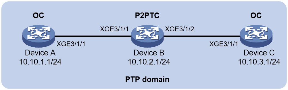
Procedure
1. Configure Device A:
# Specify the IEEE 1588 version 2 PTP profile.
<DeviceA> system-view
[DeviceA] ptp profile 1588v2
# Specify the OC clock node type.
[DeviceA] ptp mode oc
# Configure the source IP address for multicast PTP messages transmitted over IPv4 UDP.
[DeviceA] ptp source 10.10.1.1
# Specify PTP for obtaining the time on the default MDC.
[DeviceA] clock protocol ptp mdc 1
# On Ten-GigabitEthernet 3/1/1, specify the IPv4 UDP transport protocol for PTP messages and the peer delay measurement mechanism, and enable PTP.
[DeviceA] interface ten-gigabitethernet 3/1/1
[DeviceA-Ten-GigabitEthernet3/1/1] ptp transport-protocol udp [DeviceA-Ten-GigabitEthernet3/1/1] ptp delay-mechanism p2p
[DeviceA-Ten-GigabitEthernet3/1/1] ptp enable
[DeviceA-Ten-GigabitEthernet3/1/1] quit
2. Configure Device B:
# Specify the IEEE 1588 version 2 PTP profile.
<DeviceB> system-view
[DeviceB] ptp profile 1588v2
# Specify the P2PTC clock node type.
[DeviceB] ptp mode p2ptc
# Configure the source IP address for multicast PTP messages transmitted over IPv4 UDP.
[DeviceB] ptp source 10.10.2.1
# Specify PTP for obtaining the time on the default MDC.
[DeviceB] clock protocol ptp mdc 1
# On Ten-GigabitEthernet 3/1/1, specify the IPv4 UDP transport protocol for PTP messages and enable PTP.
[DeviceB] interface ten-gigabitethernet 3/1/1
DeviceB-Ten-GigabitEthernet3/1/1] ptp transport-protocol udp
[DeviceB-Ten-GigabitEthernet3/1/1] ptp enable
[DeviceB-Ten-GigabitEthernet3/1/1] quit
# On Ten-GigabitEthernet 3/1/2, specify the IPv4 UDP transport protocol for PTP messages and enable PTP.
[DeviceB] interface ten-gigabitethernet 3/1/2
[DeviceB-Ten-GigabitEthernet3/1/2] ptp transport-protocol udp
[DeviceB-Ten-GigabitEthernet3/1/2] ptp enable
[DeviceB-Ten-GigabitEthernet3/1/2] quit
3. Configure Device C:
# Specify the IEEE 1588 version 2 PTP profile.
<DeviceC> system-view
[DeviceC] ptp profile 1588v2
# Specify the OC clock node type.
[DeviceC] ptp mode oc
# Configure the source IP address for multicast PTP messages transmitted over IPv4 UDP.
[DeviceC] ptp source 10.10.3.1
# Specify PTP for obtaining the time on the default MDC.
[DeviceC] clock protocol ptp mdc 1
# On Ten-GigabitEthernet 3/1/1, specify the IPv4 UDP transport protocol for PTP messages and the peer delay measurement mechanism, and enable PTP.
[DeviceC] interface ten-gigabitethernet 3/1/1
[DeviceC-Ten-GigabitEthernet3/1/1] ptp transport-protocol udp [DeviceC-Ten-GigabitEthernet3/1/1] ptp delay-mechanism p2p
[DeviceC-Ten-GigabitEthernet3/1/1] ptp enable
[DeviceC-Ten-GigabitEthernet3/1/1] quit
Verifying the configuration
When the network is stable, perform the following tasks on Device A and Device B.
· Use the display ptp clock command to display PTP clock information.
· Use the display ptp interface brief command to display brief PTP running information for all PTP interfaces.
# Display PTP clock information on Device A.
[DeviceA] display ptp clock
PTP profile : IEEE 1588 Version 2
PTP mode : OC
Slave only : No
Sync uncertain : Disabled
Clock state : Disabled
Clock ID : 000FE2-FFFE-FF0000
Clock type : Local
Clock domain : 0
Number of PTP ports : 1
Priority1 : 128
Priority2 : 128
Clock quality :
Class : 248
Accuracy : 254
Offset (log variance) : 65535
Offset from master : 0 (ns)
Mean path delay : 0 (ns)
Steps removed : 0
Local clock time : Sun Jan 15 20:57:29 2019
Clock source info:
Clock Pri1 Pri2 Accuracy Class TimeSrc Direction In-Status Offset(log variance)
-------------------------------------------------------------------
Local 128 128 254 248 160 N/A N/A 65535
ToD0 128 128 32 6 32 In Inactive 65535
ToD1 128 128 32 6 32 N/A Inactive 65535
# Display brief PTP running information for all PTP interfaces on Device A.
[DeviceA] display ptp interface brief
Name State Delay mechanism Clock step Asymmetry correction
XGE3/1/1 Master P2P Two 0
# Display PTP clock information on Device B.
[DeviceB] display ptp clock
PTP profile : IEEE 1588 Version 2
PTP mode : P2PTC
Slave only : No
Sync uncertain : Disabled
Clock state : Disabled
Clock ID : 000FE2-FFFE-FF0001
Clock type : Local
Clock domain : 0
Number of PTP ports : 2
Priority1 : 128
Priority2 : 128
Clock quality :
Class : 248
Accuracy : 254
Offset (log variance) : 65535
Offset from master : N/A
Mean path delay : N/A
Steps removed : N/A
Local clock time : Sun Jan 15 20:57:29 2019
Clock source info:
Clock Pri1 Pri2 Accuracy Class TimeSrc Direction In-Status Offset(log variance)
-------------------------------------------------------------------
Local 128 128 254 248 160 N/A N/A 65535
ToD0 128 128 32 6 32 In Inactive 65535
ToD1 128 128 32 6 32 N/A Inactive 65535
# Display brief PTP running information for all PTP interfaces on Device B.
[DeviceB] display ptp interface brief
Name State Delay mechanism Clock step Asymmetry correction
XGE3/1/1 N/A P2P Two 0
XGE3/1/2 N/A P2P Two 0
The output shows that Device A is elected as the GM, and Ten-GigabitEthernet3/1/1 on Device A is the master port.
Example: Configuring PTP (IEEE 1588 version 2, IPv4 UDP transport, unicast transmission)
Network configuration
As shown in Figure 8, configure PTP (IEEE 1588 version 2, IPv4 UDP transport, unicast transmission) to enable Device A, Device B, Device C, and the base station to synchronize the time with the ToD clock source.
· Specify the IEEE 1588 version 2 PTP profile and unicast IPv4 UDP transport of PTP messages for Device A, Device B, and Device C.
· Assign Device A, Device B, Device C, and the base station to PTP domain 0. Specify the BC clock node type for Device A, Device B, and Device C.
· Connect Device A to the ToD clock source and Device C to the base station.
· Use the default Request_Response delay measurement mechanism on all clock nodes in the PTP domain.
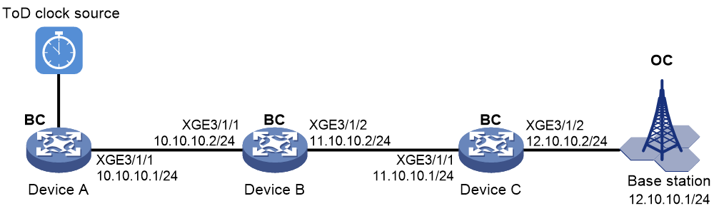
Procedure
1. Assign IP addresses to the interfaces, and make sure the devices can reach each other, as shown in Figure 8. (Details not shown.)
2. Configure Device A:
# Specify the IEEE 1588 version 2 PTP profile.
<DeviceA> system-view
[DeviceA] ptp profile 1588v2
# Specify the BC clock node type.
[DeviceA] ptp mode bc
# Configure the device to receive ToD clock signals and set the delay time correction value to 1000 nanoseconds.
[DeviceA] ptp tod0 input delay 1000
# Set priority 1 to 0 for the ToD 0 clock.
[DeviceA] ptp priority clock-source tod0 priority1 0
# On Ten-GigabitEthernet 3/1/1, configure the destination IP address for unicast PTP messages transmitted over IPv4 UDP, and enable PTP.
[DeviceA] interface ten-gigabitethernet 3/1/1
[DeviceA-Ten-GigabitEthernet3/1/1] ptp transport-protocol udp
[DeviceA-Ten-GigabitEthernet3/1/1] ptp unicast-destination 10.10.10.2
[DeviceA-Ten-GigabitEthernet3/1/1] ptp enable
[DeviceA-Ten-GigabitEthernet3/1/1] quit
3. Configure Device B:
# Specify the IEEE 1588 version 2 PTP profile.
<DeviceB> system-view
[DeviceB] ptp profile 1588v2
# Specify the BC clock node type.
[DeviceB] ptp mode bc
# Specify PTP for obtaining the time on the default MDC.
[DeviceB] clock protocol ptp mdc 1
# On Ten-GigabitEthernet 3/1/1, configure the destination IP address for unicast PTP messages transmitted over IPv4 UDP, and enable PTP.
[DeviceB] interface ten-gigabitethernet 3/1/1
[DeviceB-Ten-GigabitEthernet3/1/1] ptp transport-protocol udp
[DeviceB-Ten-GigabitEthernet3/1/1] ptp unicast-destination 10.10.10.1
[DeviceB-Ten-GigabitEthernet3/1/1] ptp enable
[DeviceB-Ten-GigabitEthernet3/1/1] quit
# On Ten-GigabitEthernet 3/1/2, configure the destination IP address for unicast PTP messages transmitted over IPv4 UDP, and enable PTP.
[DeviceB] interface ten-gigabitethernet 3/1/2
[DeviceB-Ten-GigabitEthernet3/1/2] ptp transport-protocol udp
[DeviceB-Ten-GigabitEthernet3/1/2] ptp unicast-destination 11.10.10.1
[DeviceB-Ten-GigabitEthernet3/1/2] ptp enable
[DeviceB-Ten-GigabitEthernet3/1/2] quit
4. Configure Device C:
# Specify the IEEE 1588 version 2 PTP profile.
<DeviceC> system-view
[DeviceC] ptp profile 1588v2
# Specify the BC clock node type.
[DeviceC] ptp mode bc
# Configure ToD 0 to output ToD clock signals and set the transmit delay time correction value to 100 nanoseconds.
[DeviceC] ptp tod0 output delay 100
# Specify PTP for obtaining the time on the default MDC.
[DeviceC] clock protocol ptp mdc 1
# On Ten-GigabitEthernet 3/1/1, configure the destination IP address for unicast PTP messages transmitted over IPv4 UDP, and enable PTP.
[DeviceC] interface ten-gigabitethernet 3/1/1
[DeviceC-Ten-GigabitEthernet3/1/1] ptp transport-protocol udp
[DeviceC-Ten-GigabitEthernet3/1/1] ptp unicast-destination 11.10.10.2
[DeviceC-Ten-GigabitEthernet3/1/1] ptp enable
[DeviceC-Ten-GigabitEthernet3/1/1] quit
# On Ten-GigabitEthernet3/1/2, specify IPv4 UDP transport of PTP messages, configure the destination IP address for unicast PTP messages, and enable PTP.
[DeviceC] interface ten-gigabitethernet 3/1/2
[DeviceC-Ten-GigabitEthernet3/1/2] ptp transport-protocol udp
[DeviceC-Ten-GigabitEthernet3/1/2] ptp unicast-destination 12.10.10.1
[DeviceC-Ten-GigabitEthernet3/1/2] ptp enable
[DeviceC-Ten-GigabitEthernet3/1/2] quit
5. Configure the base station.
# Specify PTP domain 0.
# Specify IPv4 UDP transport of PTP messages.
# Set the destination IP address of unicast PTP messages to 12.10.10.2.
# Specify the Request_Response delay measurement mechanism.
For more information, see the configuration guide for the base station.
Verifying the configuration
When the network is stable, perform the following tasks:
· Use the display ptp clock command to display PTP clock information.
· Use the display ptp interface brief command to display brief PTP running information for all PTP interfaces.
# Display PTP clock information on Device A.
[DeviceA] display ptp clock
PTP profile : IEEE 1588 Version 2
PTP mode : BC
Slave only : No
Sync uncertain : Disabled
Clock state : Disabled
Clock ID : 000FE2-FFFE-FF0000
Clock type : ToD0
ToD direction : In
ToD delay time : 1000 (ns)
Clock domain : 0
Number of PTP ports : 1
Priority1 : 0
Priority2 : 128
Clock quality :
Class : 6
Accuracy : 32
Offset (log variance) : 65535
Offset from master : 0 (ns)
Mean path delay : 0 (ns)
Steps removed : 0
Local clock time : Sun Jan 15 20:57:29 2019
Clock source info:
Clock Pri1 Pri2 Accuracy Class TimeSrc Direction In-Status Offset(log variance)
-------------------------------------------------------------------
Local 128 128 254 248 160 N/A N/A 65535
ToD0 128 128 32 6 32 In Active 65535
ToD1 128 128 32 6 32 N/A Inactive 65535
# Display brief PTP running information for all PTP interfaces on Device A.
[DeviceA] display ptp interface brief
Name State Delay mechanism Clock step Asymmetry correction
XGE3/1/1 Master E2E Two 0
# Display PTP clock information on Device C.
[DeviceC] display ptp clock
PTP profile : IEEE 1588 Version 2
PTP mode : BC
Slave only : No
Sync uncertain : Disabled
Clock state : Disabled
Clock ID : 000FE2-FFFE-FF0001
Clock type : Local
Clock domain : 0
Number of PTP ports : 2
Priority1 : 128
Priority2 : 128
Clock quality :
Class : 248
Accuracy : 254
Offset (log variance) : 65535
Offset from master : 50 (ns)
Mean path delay : 2791 (ns)
Steps removed : 2
Local clock time : Sun Jan 15 20:57:29 2019
Clock source info:
Clock Pri1 Pri2 Accuracy Class TimeSrc Direction In-Status Offset(log variance)
-------------------------------------------------------------------
Local 128 128 254 248 160 N/A N/A 65535
ToD0 128 128 32 6 32 In Inactive 65535
ToD1 128 128 32 6 32 N/A Inactive 65535
# Display brief PTP running information for all PTP interfaces on Device C.
[DeviceC] display ptp interface brief
Name State Delay mechanism Clock step Asymmetry correction
XGE3/1/1 Slave E2E Two 0
XGE3/1/2 Master E2E Two 0
The output shows that Device A is elected as the GM, and Ten-GigabitEthernet3/1/1 on Device A is the master port.
Example: Configuring PTP (ITU-T G.8275.1, IEEE 802.3/Ethernet transport, multicast transmission)
Network configuration
As shown in Figure 9, configure PTP (ITU-T G.8275.1, IEEE 802.3/Ethernet transport, multicast transmission) to enable Device A to synchronize Device B.
· Specify the ITU-T G.8275.1 PTP profile for Device A and Device B.
· Assign Device A and Device B to the same PTP domain. Specify the T-BC clock node type for Device A and T-TSC clock node type for Device B.
· Use the default Request_Response delay measurement mechanism on Device A and Device B.
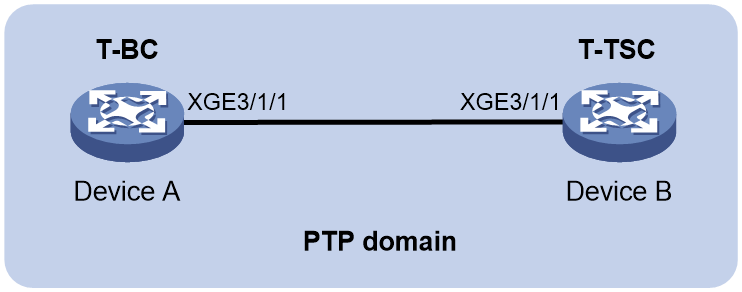
Procedure
|
|
IMPORTANT: The ITU-T G.8275.1 PTP profile transports PTP messages over IEEE 802.3/Ethernet rather than IPv4 UDP and in multicast rather than unicast mode. |
1. Configure Device A:
# Specify the ITU-T G.8275.1 PTP profile.
<DeviceA> system-view
[DeviceA] ptp profile g8275.1
# Specify the T-BC clock node type.
[DeviceA] ptp mode t-bc
# Specify PTP for obtaining the time on the default MDC.
[DeviceA] clock protocol ptp mdc 1
# Enable PTP on Ten-GigabitEthernet 3/1/1.
[DeviceA] interface ten-gigabitethernet 3/1/1
[DeviceA-Ten-GigabitEthernet3/1/1] ptp enable
[DeviceA-Ten-GigabitEthernet3/1/1] quit
2. Configure Device B:
# Specify the ITU-T G.8275.1 PTP profile.
<DeviceB> system-view
[DeviceB] ptp profile g8275.1
# Specify the T-TSC clock node type.
[DeviceB] ptp mode t-tsc
# Specify PTP for obtaining the time on the default MDC.
[DeviceB] clock protocol ptp mdc 1
# Enable PTP on Ten-GigabitEthernet 3/1/1.
[DeviceB] interface ten-gigabitethernet 3/1/1
[DeviceB-Ten-GigabitEthernet3/1/1] ptp enable
[DeviceB-Ten-GigabitEthernet3/1/1] quit
Verifying the configuration
When the network is stable, perform the following tasks:
· Use the display ptp clock command to display PTP clock information.
· Use the display ptp interface brief command to display brief PTP running information for all PTP interfaces.
# Display PTP clock information on Device A.
[DeviceA] display ptp clock
PTP profile : ITU-T G.8275.1
PTP mode : T-BC
Slave only : No
Sync uncertain : Disabled
Clock state : Disabled
Clock ID : 24881D-FFFE-F20100
Clock type : Local
Clock domain : 24
Number of PTP ports : 1
Priority1 : 128
Priority2 : 128
Local priority : 128
Clock quality :
Class : 248
Accuracy : 254
Offset (log variance) : 65535
Offset from master : 0 (ns)
Mean path delay : 0 (ns)
Steps removed : 0
Local clock time : Fri Dec 7 00:59:44 2018
Clock source info:
Clock Pri1 Pri2 Accuracy Class TimeSrc Direction In-Status Offset(log variance)
-------------------------------------------------------------------
Local 128 128 254 248 160 N/A N/A 65535
ToD0 128 128 32 6 32 In Inactive 65535
ToD1 128 128 32 6 32 N/A Inactive 65535
# Display brief PTP running information for all PTP interfaces on Device A.
[DeviceA] display ptp interface brief
Name State Delay mechanism Clock step Asymmetry correction
XGE3/1/1 Master E2E Two 0
# Display PTP clock information on Device B.
[DeviceB] display ptp clock
PTP profile : ITU-T G.8275.1
PTP mode : T-TSC
Slave only : No
Sync uncertain : Disabled
Clock state : Disabled
Clock ID : 2461E3-FFFE-A20200
Clock type : Local
Clock domain : 24
Number of PTP ports : 1
Priority1 : 128
Priority2 : 255
Local priority : 128
Clock quality :
Class : 255
Accuracy : 254
Offset (log variance) : 65535
Offset from master : 49915149500000 (ns)
Mean path delay : 500000 (ns)
Steps removed : 1
Local clock time : Fri Dec 7 14:52:54 2018
Clock source info:
Clock Pri1 Pri2 Accuracy Class TimeSrc Direction In-Status Offset(log variance)
-------------------------------------------------------------------
Local 128 128 254 248 160 N/A N/A 65535
ToD0 128 128 32 6 32 In Inactive 65535
ToD1 128 128 32 6 32 N/A Inactive 65535
# Display brief PTP running information for all PTP interfaces on Device B.
[DeviceB] display ptp interface brief
Name State Delay mechanism Clock step Asymmetry correction
XGE3/1/1 Slave E2E Two 0
The output shows that Device A is elected as the GM, and Ten-GigabitEthernet3/1/1 on Device A is the master port.
Example: Configuring PTP (ITU-T G.8275.2, IPv4 UDP encapsulation, unicast transmission)
Network configuration
As shown in Figure 10, Device A and Device B are in a PTP domain. The switch is a Layer 2 switch that does not support PTP. Configure PTP (ITU-TG.8275.2, IPv4 UDP encapsulation, unicast transmission) to enable Device B to synchronize to Device A.
· Specify the ITU-TG.8275.2 PTP profile for Device A and Device B.
· Use the default Request_Response delay measurement mechanism on Device A and Device B.
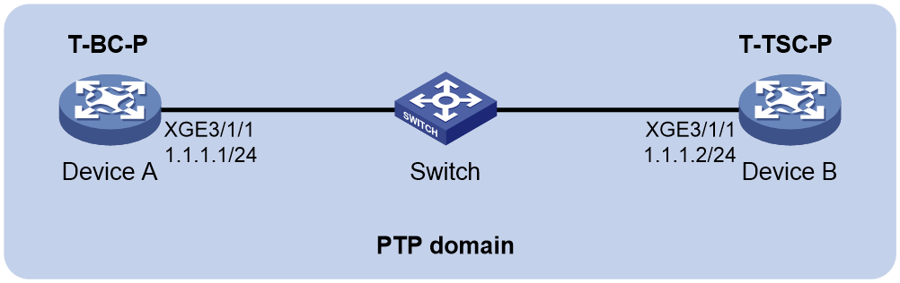
Prerequisites
Configure IP addresses and routing protocols for the devices. Make sure the devices are reachable to each other.
Procedure
|
|
IMPORTANT: The ITU-T G.8275.2 PTP profile transports PTP messages over IPv4 UDP rather than IEEE 802.3/Ethernet and in unicast rather than multicast mode. |
1. Configure Device A:
# Specify the ITU-T G.8275.2 PTP profile.
<DeviceA> system-view
[DeviceA] ptp profile g8275.2
# Specify the T-BC-P clock node type.
[DeviceA] ptp mode t-bc-p
# Specify PTP for obtaining the time on the default MDC.
[DeviceA] clock protocol ptp mdc 1
# Enable PTP and configure PTP parameters on Ten-GigabitEthernet 3/1/1.
[DeviceA] interface ten-gigabitethernet 3/1/1
[DeviceA-Ten-GigabitEthernet3/1/1] ptp unicast-destination 1.1.1.2
[DeviceA-Ten-GigabitEthernet3/1/1] ptp unicast-negotiate grant-port
[DeviceA-Ten-GigabitEthernet3/1/1] ptp notslave disable
[DeviceA-Ten-GigabitEthernet3/1/1] ptp enable
[DeviceA-Ten-GigabitEthernet3/1/1] quit
2. Configure Device B:
# Specify the ITU-T G.8275.2 PTP profile.
<DeviceB> system-view
[DeviceB] ptp profile g8275.2
# Specify the T-TSC-P clock node type.
[DeviceB] ptp mode t-tsc-p
# Specify PTP for obtaining the time on the default MDC.
[DeviceB] clock protocol ptp mdc 1
# Enable PTP on Ten-GigabitEthernet 3/1/1.
[DeviceB] interface ten-gigabitethernet 3/1/1
[DeviceB-Ten-GigabitEthernet3/1/1] ptp unicast-destination 1.1.1.1
[DeviceB-Ten-GigabitEthernet3/1/1] ptp unicast-negotiate request-port
[DeviceB-Ten-GigabitEthernet3/1/1] ptp enable
[DeviceB-Ten-GigabitEthernet3/1/1] quit
Verifying the configuration
When the network is stable, perform the following tasks:
· Use the display ptp clock command to display PTP clock information.
· Use the display ptp interface brief command to display brief PTP running information for all interfaces.
# Display PTP clock information on Device A.
[DeviceA] display ptp clock
PTP profile : ITU-T G.8275.2
PTP mode : T-BC-P
Slave only : No
Sync uncertain : Disabled
Clock state : Disabled
Clock ID : 140570-FFFE-930100
Clock type : Local
Clock domain : 44
Number of PTP ports : 1
Priority1 : 128
Priority2 : 128
Clock quality :
Class : 248
Accuracy : 254
Offset (log variance) : 65535
Offset from master : 0 (ns)
Mean path delay : 0 (ns)
Steps removed : 0
Local clock time : Sat May 9 10:38:42 2020
Clock source info:
Clock LP Pri2 Accuracy Class TimeSrc Direction In-Status Offset(log variance)
-------------------------------------------------------------------
Local 128 128 254 248 160 N/A N/A 65535
ToD0 128 128 32 6 32 N/A Inactive 65535
ToD1 128 128 32 6 32 N/A Inactive 65535
# Display brief PTP running information on Device A.
[DeviceA] display ptp interface brief
Name State Delay mechanism Clock step Asymmetry correction
XGE3/1/1 Master E2E Two 0
# Display PTP clock information on Device B.
[DeviceB] display ptp clock
PTP profile : ITU-T G.8275.2
PTP mode : T-TSC-P
Slave only : No
Sync uncertain : Disabled
Clock state : Disabled
Clock ID : 147405-FFFE-E30200
Clock type : Local
Clock domain : 44
Number of PTP ports : 1
Priority1 : 128
Priority2 : 255
Clock quality :
Class : 255
Accuracy : 254
Offset (log variance) : 65535
Offset from master : 50 (ns)
Mean path delay : 2169 (ns)
Steps removed : 1
Local clock time : Sat May 9 10:40:04 2020
Clock source info:
Clock LP Pri2 Accuracy Class TimeSrc Direction In-Status Offset(log variance)
-------------------------------------------------------------------
Local 128 255 254 255 160 N/A N/A 65535
ToD0 128 255 254 255 32 N/A Inactive 65535
ToD1 128 255 254 255 32 N/A Inactive 65535
# Display brief PTP running information on Device B.
[DeviceB] display ptp interface brief
Name State Delay mechanism Clock step Asymmetry correction
GE1/0/2 Slave E2E Two 0
The output shows that Device A has been elected as the GM, and Ten-GigabitEthernet 3/1/1 on Device A is the master port.
