- Table of Contents
-
- 15-Network Management and Monitoring Configuration Guide
- 00-Preface
- 01-System maintenance and debugging configuration
- 02-NQA configuration
- 03-iNQA configuration
- 04-iFIT configuration
- 05-SRPM configuration
- 06-NTP configuration
- 07-PTP configuration
- 08-Network synchronization configuration
- 09-SNMP configuration
- 10-RMON configuration
- 11-NETCONF configuration
- 12-CWMP configuration
- 13-EAA configuration
- 14-Process monitoring and maintenance configuration
- 15-Sampler configuration
- 16-Mirroring configuration
- 17-NetStream configuration
- 18-IPv6 NetStream configuration
- 19-TCP connection trace configuration
- 20-Performance management configuration
- 21-Fast log output configuration
- 22-Flow log configuration
- 23-Information center configuration
- 24-Packet capture configuration
- 25-Flow monitor configuration
- Related Documents
-
| Title | Size | Download |
|---|---|---|
| 02-NQA configuration | 1.25 MB |
Restrictions and guidelines: NQA configuration
Configuring NQA operations on the NQA client
NQA operations tasks at a glance
Configuring the ICMP echo operation
Configuring the ICMP jitter operation
Configuring the DHCP operation
Configuring the HTTP operation
Configuring the UDP jitter operation
Configuring the SNMP operation
Configuring the UDP echo operation
Configuring the UDP tracert operation
Configuring the voice operation
Configuring the DLSw operation
Configuring the path jitter operation
Configuring the Y.1564 operation
Configuring path quality analysis operations
Configuring optional parameters for the NQA operation
Configuring the collaboration feature
Configuring threshold monitoring
Configuring the NQA statistics collection feature
Configuring the saving of NQA history records
Scheduling the NQA operation on the NQA client
Configuring NQA templates on the NQA client
NQA template tasks at a glance
Configuring the TCP half open template
Configuring the HTTPS template
Configuring the RADIUS template
Configuring optional parameters for the NQA template
Display and maintenance commands for NQA
NQA operation configuration examples
Example: Configuring the ICMP echo operation
Example: Configuring the ICMP jitter operation
Example: Configuring the DHCP operation
Example: Configuring the DNS operation
Example: Configuring the FTP operation
Example: Configuring the HTTP operation
Example: Configuring the UDP jitter operation
Example: Configuring the SNMP operation
Example: Configuring the TCP operation
Example: Configuring the UDP echo operation
Example: Configuring the UDP tracert operation
Example: Configuring the voice operation
Example: Configuring the DLSw operation
Example: Configuring the path jitter operation
Example: Configuring the path quality analysis operation
Example: Configuring Y.1564 operation on a Layer 2 Ethernet network
Example: Configuring Y.1564 operation on a Layer 3 Ethernet network
Example: Configuring Y.1564 operation on a Layer 3 Ethernet gateway
Example: Configuring Y.1564 operation on an L2VPN network
Example: Configuring Y.1564 operation on an L3VPN network
Example: Configuring Y.1564 operation on an L3VPN gateway
Example: Configuring Y.1564 operation on an L3VPN Network through an L2VPN
Example: Configuring Y.1564 operation on an L3VPN gateway through an L2VPN
Example: Configuring NQA collaboration
NQA template configuration examples
Example: Configuring the ARP template
Example: Configuring the ICMP template
Example: Configuring the IMAP template
Example: Configuring the DNS template
Example: Configuring the POP3 template
Example: Configuring the SMTP template
Example: Configuring the TCP template
Example: Configuring the TCP half open template
Example: Configuring the UDP template
Example: Configuring the HTTP template
Example: Configuring the HTTPS template
Example: Configuring the FTP template
Example: Configuring the RADIUS template
Example: Configuring the SNMP template
Example: Configuring the SSL template
Restrictions and guidelines: TWAMP configuration
Configuring the TWAMP reflector
Display and maintenance commands for TWAMP
Example: Configuring TWAMP test
TWAMP Light operating mechanism
Restrictions and guidelines: TWAMP Light configuration
Configuring the TWAMP Light server
Configuring the TWAMP Light client
Enabling checksum field adjustment for test packets globally
Creating a test session on the TWAMP Light client
Configuring the IP address and port number for the TWAMP Light test session
Configuring other parameters for the TWAMP Light probe packets
Enabling TWAMP Light for all member interfaces of an aggregate interface
Enabling one-way delay measurement
Configuring threshold monitoring
Start the test on the TWAMP Light sender
Stop the test on the TWAMP Light sender
Display and maintenance commands for TWAMP Light
TWAMP Light configuration examples
Example: Configuring TWAMP Light test on a common Layer 3 network
Example: Configuring TWAMP Light test on an L2VPN network
Example: Configuring TWAMP Light test on an L3VPN network
Configuring NQA
About NQA
Network quality analyzer (NQA) allows you to measure network performance, verify the service levels for IP services and applications, and troubleshoot network problems.
NQA architecture
An NQA operation contains a set of parameters such as the operation type, destination IP address, and port number to define how the operation is performed. Each NQA operation is identified by the combination of the administrator name and the operation tag.
As shown in Figure 1, the NQA architecture contains the following parts:
· NQA client—Sends probe packets to the NQA destination device by simulating IP services and applications to measure network performance. You can configure the NQA client to run the operation at scheduled time periods.
· NQA server—Destination device of the NQA operation. It receives, processes, and responds to the probe packets sent by the NQA client.

NQA operating mechanism
The NQA client and NQA server interact as follows:
1. The NQA client constructs probe packets of the operation type, and sends them to the NQA server.
2. The NQA server processes the probe packets and sends back reply packets.
3. Upon receiving the replies, the NQA client calculates the packet loss ratio and round-trip time to determine the network performance and service quality.
After an NQA operation starts, the NQA client repeats the operation at the specified interval.
An NQA operation can contain multiple probes. You can set the number of probes the NQA client performs in an operation. For the voice and path jitter operations, the NQA client performs only one probe per operation.
Collaboration with Track
NQA can collaborate with the Track module to notify application modules of state or performance changes so that the application modules can take predefined actions.
The NQA + Track collaboration is available for the following application modules:
· VRRP.
· Static routing.
· Policy-based routing.
· Traffic redirecting.
The following describes how a static route destined for 192.168.0.88 is monitored through collaboration:
1. NQA monitors the reachability to 192.168.0.88.
2. When 192.168.0.88 becomes unreachable, NQA notifies the Track module of the change.
3. The Track module notifies the static routing module of the state change.
4. The static routing module sets the static route to invalid according to a predefined action.
For more information about collaboration, see High Availability Configuration Guide.
Threshold monitoring
Threshold monitoring enables the NQA client to take a predefined action when the NQA operation performance metrics violate the specified thresholds.
Table 1 describes the relationships between performance metrics and NQA operation types.
Table 1 Performance metrics and NQA operation types
|
Performance metric |
NQA operation types that can gather the metric |
|
Probe duration |
All NQA operation types except UDP jitter, UDP tracert, path jitter, and voice |
|
Number of probe failures |
All NQA operation types except UDP jitter, UDP tracert, path jitter, and voice |
|
Round-trip time |
ICMP jitter, UDP jitter, and voice |
|
Number of discarded packets |
ICMP jitter, UDP jitter, and voice |
|
One-way jitter (source-to-destination or destination-to-source) |
ICMP jitter, UDP jitter, and voice |
|
One-way delay (source-to-destination or destination-to-source) |
ICMP jitter, UDP jitter, and voice |
|
Calculated Planning Impairment Factor (ICPIF) (see "Configuring the voice operation") |
Voice |
|
Mean Opinion Scores (MOS) (see "Configuring the voice operation") |
Voice |
NQA templates
An NQA template is a set of parameters (such as destination address and port number) that defines how an NQA operation is performed. Features can use the NQA template to collect statistics.
You can create multiple NQA templates on the NQA client. Each template must be identified by a unique template name.
Restrictions and guidelines: NQA configuration
In standard system operating mode, only the following cards support Y.1564 operations and path quality analysis operations:
CSPEX-1802X, CSPEX-1802XA, CSPEX-1812X-E, CSPEX-2304X-G, CEPC-CQ8L, CEPC-CQ8LA, CEPC-CQ16L1, CSPEX-1502XA, RX-SPE200-E
In SDN-WAN system operating mode, only the following cards support Y.1564 operations and path quality analysis operations:
CSPEX-1304X, CSPEX-1404X, CSPEX-1502X, CSPEX-1504X, CSPEX-1504XA, CSPEX-1602X, CSPEX-1602XA, CSPEX-1804X, CSPEX-1512X, CSPEX-1612X, CSPEX-1812X, RX-SPE200, CEPC-XP4LX, CEPC-XP24LX, CEPC-XP48RX, CEPC-CP4RX, CEPC-CP4RXA, CEPC-CP4RX-L, CSPEX-1802X, CSPEX-1802XA, CSPEX-1812X-E, CSPEX-2304X-G, CEPC-CQ8L, CEPC-CQ8LA, CEPC-CQ16L1, CSPEX-1502XA, RX-SPE200-E
You must configure the VLAN ID for probe packets to test a subinterface by using the vlan command in operation type view.
In an SRv6 network, to avoid probe failures caused by packet fragmentation, make sure the sum of probe packet size and SRv6 packet header (SRH) size is not greater than the MTU size of any interface on the test link. To set the probe packet size, use the frame-size command (for Y.1564 operations and path quality analysis operations) or data-size command (for TWAMP Light tests).
To avoid probe failures, follow these restrictions and guidelines when configuring the listening ports on the NQA client and NQA server:
· Do not specify a well-known port.
· Make sure the specified port number is not used by any services on the device.
¡ To obtain the IPv4 addresses and the port numbers in use on this device, see the Local Addr:port field in the output from the display tcp and display udp commands.
¡ To obtain the IPv6 addresses and the port numbers in use on this device, see the LAddr->port field in the output from the display ipv6 tcp and display ipv6 udp commands.
The destination port configured for the operation (with the destination port command) on the NQA client must be the same as the listening port configured on the server.
For latency operation results to be accurate, synchronize time between the source and the destination with an accuracy higher than or equal to the operation result calculation accuracy.
NQA tasks at a glance
To configure NQA, perform the following tasks:
Perform this task on the destination device before you configure the ICMP jitter, TCP, UDP echo, UDP jitter, and voice operations.
3. Configuring NQA operations or NQA templates
Choose the following tasks as needed:
¡ Configuring NQA operations on the NQA client
¡ Configuring NQA templates on the NQA client
After you configure an NQA operation, you can schedule the NQA client to run the NQA operation.
An NQA template does not run immediately after it is configured. The template creates and run the NQA operation only when it is required by the feature to which the template is applied.
Configuring the NQA server
Restrictions and guidelines
Follow these restrictions and guidelines to determine the configuration on the destination device:
· To perform ICMP jitter, TCP, UDP echo, UDP jitter, and voice operations, you must enable the NQA server on the destination device and configure TCP or UDP listening services.
· To perform path quality analysis operations and Y.1564 operations, you must enable the NQA server on the destination device and packet reflection.
· To perform other NQA operations, you only need to enable the corresponding services on the destination device.
The NQA server listens and responds to requests on the specified IP addresses and ports. You can configure multiple TCP or UDP listening services on an NQA server, where each corresponds to a specific IP address and port number. You can configure multiple ICMP listening services on an NQA server. Each listening service corresponds to one IP address.
The IP address, port number, and VPN instance for a listening service must be unique on the NQA server and match the configuration on the NQA client.
Procedure
1. Enter system view.
system-view
2. (Optional.) Configure a TCP listening service.
nqa server tcp-connect { ipv4-address | ipv6 ipv6-address } port-number [ vpn-instance vpn-instance-name ] [ tos tos ]
This task is required for only TCP and DLSw operations. For the DLSw operation, the port number for the TCP listening service must be 2065.
3. (Optional.) Configure a UDP listening service.
nqa server udp-echo { ipv4-address | ipv6 ipv6-address } port-number [ vpn-instance vpn-instance-name ] [ high-performance-mode ] [ tos tos ]
This task is required for only UDP echo, UDP jitter, and voice operations.
4. Configure a reflector on the NQA server.
nqa reflector reflector-id interface interface-type interface-number [ service-instance instance-id ] [ { ip | ipv6 } { destination address1 [ to address2 ] | source address1 [ to address2 ] } * | source-port port-number1 [ to port-number2 ] | destination-port port-number1 [ to port-number2 ] | destination-mac mac-address1 [ to mac-address2 ] | source-mac mac-address1 [ to mac-address2 ] | vlan { vlan-id1 [ to vlan-id2 ] | s-vid vlan-id1 [ to vlan-id2 ] c-vid vlan-id1 [ to vlan-id2 ] } | exchange-port | vpn-instance vpn-instance-name ] *
By default, no reflector is configured on the device.
5. (Optional.) Configure an ICMP reflector on the NQA server.
nqa server icmp-server { ipv4-address | ipv6 ipv6-address } [ vpn-instance vpn-instance-name ] [ tos tos ]
By default, no ICMP reflector is configured on the NQA server.
This configuration applies only to ICMP jitter operations in echo packet mode.
6. Enable the NQA server.
nqa server enable
By default, the NQA server is disabled.
Enabling the NQA client
1. Enter system view.
system-view
2. Enable the NQA client.
nqa agent enable
By default, the NQA client is enabled.
The NQA client configuration takes effect after you enable the NQA client.
Configuring NQA operations on the NQA client
NQA operations tasks at a glance
You can configure multiple NQA operations on a device and run them at the same time.
To configure NQA operations, perform the following tasks:
1. Configuring an NQA operation
¡ Configuring the ICMP echo operation
¡ Configuring the ICMP jitter operation
¡ Configuring the DHCP operation
¡ Configuring the DNS operation
¡ Configuring the FTP operation
¡ Configuring the HTTP operation
¡ Configuring the UDP jitter operation
¡ Configuring the SNMP operation
¡ Configuring the TCP operation
¡ Configuring the UDP echo operation
¡ Configuring the UDP tracert operation
¡ Configuring the voice operation
¡ Configuring the DLSw operation
¡ Configuring the path jitter operation
¡ Configuring the Y.1564 operation
¡ Configuring path quality analysis operations
2. (Optional.) Configuring optional parameters for the NQA operation
3. (Optional.) Configuring the collaboration feature
4. (Optional.) Configuring threshold monitoring
5. (Optional.) Configuring the NQA statistics collection feature
6. (Optional.) Configuring the saving of NQA history records
7. Scheduling the NQA operation on the NQA client
Configuring the ICMP echo operation
About this task
The ICMP echo operation measures the reachability of a destination device. It has the same function as the ping command, but provides more output information. In addition, if multiple paths exist between the source and destination devices, you can specify the next hop for the ICMP echo operation.
The ICMP echo operation sends an ICMP echo request to the destination device per probe.
Procedure
1. Enter system view.
system-view
2. Create an NQA operation and enter NQA operation view.
nqa entry admin-name operation-tag
3. Specify the ICMP echo type and enter its view.
type icmp-echo
4. Specify the destination address for ICMP echo requests.
IPv4:
destination ip ip-address
By default, no destination address is specified.
IPv6:
destination ipv6 ipv6-address
By default, no destination address is specified.
5. Specify the source IP address for ICMP echo requests. Choose one option as needed:
¡ Use the IP address of the specified interface as the source IP address.
source interface interface-type interface-number
By default, the source IP address of ICMP echo requests is the primary IP address of their output interface.
The specified source interface must be up.
¡ Specify the source IPv4 address.
source ip ip-address
By default, the source IPv4 address of ICMP echo requests is the primary IPv4 address of their output interface.
The specified source IPv4 address must be the IPv4 address of a local interface, and the interface must be up. Otherwise, no probe packets can be sent out.
¡ Specify the source IPv6 address.
source ipv6 ipv6-address
By default, the source IPv6 address of ICMP echo requests is the primary IPv6 address of their output interface.
The specified source IPv6 address must be the IPv6 address of a local interface, and the interface must be up. Otherwise, no probe packets can be sent out.
6. Specify the output interface or the next hop IP address for ICMP echo requests. Choose one option as needed:
¡ Specify the output interface for ICMP echo requests.
out interface interface-type interface-number
By default, the output interface for ICMP echo requests is not specified. The NQA client determines the output interface based on the routing table lookup.
¡ Specify the next hop IPv4 address.
next-hop ip ip-address
By default, no next hop IPv4 address is specified.
¡ Specify the next hop IPv6 address.
next-hop ipv6 ipv6-address
By default, no next hop IPv6 address is specified.
7. (Optional.) Set the payload size for each ICMP echo request.
data-size size
The default payload size is 100 bytes.
8. (Optional.) Specify the payload fill string for ICMP echo requests.
data-fill string
The default payload fill string is the hexadecimal string 00010203040506070809.
Configuring the ICMP jitter operation
About this task
The ICMP jitter operation measures unidirectional and bidirectional jitters. The operation result helps you to determine whether the network can carry jitter-sensitive services such as real-time voice and video services.
The ICMP jitter operation works as follows:
1. The NQA client sends ICMP packets to the destination device.
2. The destination device time stamps each packet it receives, and then sends the packet back to the NQA client.
3. Upon receiving the responses, the NQA client calculates the jitter according to the timestamps.
The ICMP jitter operation sends a number of ICMP packets to the destination device per probe. The number of packets to send is determined by using the probe packet-number command.
Restrictions and guidelines
The display nqa history command does not display the results or statistics of the ICMP jitter operation. To view the results or statistics of the operation, use the display nqa result or display nqa statistics command.
Before starting the operation, make sure the network devices are time synchronized by using NTP. For more information about NTP, see "Configuring NTP."
Procedure
1. Enter system view.
system-view
2. Create an NQA operation and enter NQA operation view.
nqa entry admin-name operation-tag
3. Specify the ICMP jitter type and enter its view.
type icmp-jitter
4. Specify the destination address for the probe packets.
IPv4:
destination ip ip-address
By default, no destination address is specified for the probe packet.
IPv6:
destination ipv6 ipv6-address
By default, no destination address is specified for the probe packet.
5. Specify the packet mode for the ICMP jitter operation.
icmp-jitter-mode { icmp-echo | icmp-timestamp }
By default, an ICMP jitter operation is in timestamp packet mode.
6. Set the number of ICMP packets sent per probe.
probe packet-number number
The default setting is 10.
7. Set the interval for sending ICMP packets.
probe packet-interval interval
The default setting is 20 milliseconds.
8. Specify how long the NQA client waits for a response from the server before it regards the response times out.
probe packet-timeout timeout
The default setting is 3000 milliseconds.
9. Specify the source address for the probe packets.
IPv4:
source ip ip-address
By default, the source IPv4 address of the probe packets is the primary IPv4 address of their output interface.
The specified source IPv4 address must be the IPv4 address of a local interface, and the interface must be up. Otherwise, no probe packets can be sent out.
IPv6:
source ipv6 ipv6-address
By default, the source IPv6 address of the probe packets is the IPv6 address of their output interface.
The specified source IPv6 address must be the IPv6 address of a local interface, and the interface must be up. Otherwise, no probe packets can be sent out.
10. (Optional.) Set the payload size for the probe packets.
data-size size
The default payload size is 20 bytes.
An ICMP jitter operation in timestamp packet mode does not support this command.
11. (Optional.) Specify the payload fill string for ICMP echo requests.
data-fill string
The default payload fill string is the hexadecimal string 00010203040506070809.
An ICMP jitter operation in timestamp packet mode does not support this command.
Configuring the DHCP operation
About this task
The DHCP operation measures whether or not the DHCP server can respond to client requests. DHCP also measures the amount of time it takes the NQA client to obtain an IP address from a DHCP server.
The NQA client simulates the DHCP relay agent to forward DHCP requests for IP address acquisition from the DHCP server. The interface that performs the DHCP operation does not change its IP address. When the DHCP operation completes, the NQA client sends a packet to release the obtained IP address.
The DHCP operation acquires an IP address from the DHCP server per probe.
Procedure
1. Enter system view.
system-view
2. Create an NQA operation and enter NQA operation view.
nqa entry admin-name operation-tag
3. Enable the DHCP service.
dhcp enable
By default, the DHCP service is disabled.
4. Specify the DHCP type and enter its view.
type dhcp
5. Specify the IP address of the DHCP server as the destination IP address of DHCP packets.
destination ip ip-address
By default, no destination IP address is specified.
6. Specify the output interface for DHCP request packets.
out interface interface-type interface-number
By default, the NQA client determines the output interface based on the routing table lookup.
7. Specify the source IP address of DHCP request packets.
source ip ip-address
By default, the source IP address of DHCP request packets is the primary IP address of their output interface.
The specified source IP address must be the IP address of a local interface, and the local interface must be up. Otherwise, no probe packets can be sent out.
Configuring the DNS operation
About this task
The DNS operation simulates domain name resolution, and it measures the time for the NQA client to resolve a domain name into an IP address through a DNS server. The obtained DNS entry is not saved.
The DNS operation resolves a domain name into an IP address per probe.
Procedure
1. Enter system view.
system-view
2. Create an NQA operation and enter NQA operation view.
nqa entry admin-name operation-tag
3. Specify the DNS type and enter its view.
type dns
4. Specify the destination address for the probe packets.
IPv4:
destination ip ip-address
By default, no destination address is specified for the probe packet.
IPv6:
destination ipv6 ipv6-address
By default, no destination address is specified for the probe packet.
5. Specify the domain name to be translated.
resolve-target domain-name
By default, no domain name is specified.
Specify the domain name resolution type.
resolve-type { A | AAAA }
By default, the domain name resolution type is type A.
A type A query resolves a domain name to a mapped IPv4 address. A type AAAA query resolves a domain name to a mapped IPv6 address.
Configuring the FTP operation
About this task
The FTP operation measures the time for the NQA client to transfer a file to or download a file from an FTP server.
The FTP operation uploads or downloads a file from an FTP server per probe.
Restrictions and guidelines
To upload (put) a file to the FTP server, use the filename command to specify the name of the file you want to upload. The file must exist on the NQA client.
To download (get) a file from the FTP server, include the name of the file you want to download in the url command. The file must exist on the FTP server. The NQA client does not save the file obtained from the FTP server.
Use a small file for the FTP operation. A big file might result in transfer failure because of timeout, or might affect other services because of the amount of network bandwidth it occupies.
Procedure
1. Enter system view.
system-view
2. Create an NQA operation and enter NQA operation view.
nqa entry admin-name operation-tag
3. Specify the FTP type and enter its view.
type ftp
4. Specify an FTP login username.
username username
By default, no FTP login username is specified.
5. Specify an FTP login password.
password { cipher | simple } string
By default, no FTP login password is specified.
6. Specify the source address for FTP request packets.
IPv4:
source ip ip-address
By default, the source IP address of FTP request packets is the primary IPv4 address of their output interface.
The source IP address must be the IP address of a local interface, and the interface must be up. Otherwise, no FTP requests can be sent out.
IPv6:
source ipv6 ipv6-address
By default, the source IP address of FTP request packets is the IPv6 address of their output interface.
The source IP address must be the IPv6 address of a local interface, and the interface must be up. Otherwise, no FTP requests can be sent out.
7. Set the data transmission mode.
mode { active | passive }
The default mode is active.
8. Specify the FTP operation type.
operation { get | put }
The default FTP operation type is get.
9. Specify the destination URL for the FTP operation.
url url
By default, no destination URL is specified for an FTP operation.
Enter the URL in one of the following formats:
¡ ftp://host/filename.
¡ ftp://host:port/filename.
The filename argument is required only for the get operation.
10. Specify the name of the file to be uploaded.
filename file-name
By default, no file is specified.
This task is required only for the put operation.
The configuration does not take effect for the get operation.
Configuring the HTTP operation
About this task
The HTTP operation measures the time for the NQA client to obtain responses from an HTTP server.
The HTTP operation supports the following operation types:
· Get—Retrieves data such as a Web page from the HTTP server.
· Post—Sends data to the HTTP server for processing.
· Raw—Sends a user-defined HTTP request to the HTTP server. You must manually configure the content of the HTTP request to be sent.
The HTTP operation completes the operation of the specified type per probe.
Procedure
1. Enter system view.
system-view
2. Create an NQA operation and enter NQA operation view.
nqa entry admin-name operation-tag
3. Specify the HTTP type and enter its view.
type http
4. Specify the destination URL for the HTTP operation.
url url
By default, no destination URL is specified for an HTTP operation.
Enter the URL in one of the following formats:
¡ http://host/resource
¡ http://host:port/resource
5. Specify an HTTP login username.
username username
By default, no HTTP login username is specified.
6. Specify an HTTP login password.
password { cipher | simple } string
By default, no HTTP login password is specified.
7. Specify the HTTP version.
version { v1.0 | v1.1 }
By default, HTTP 1.0 is used.
8. Specify the HTTP operation type.
operation { get | post | raw }
The default HTTP operation type is get.
If you set the operation type to raw, the client pads the content configured in raw request view to the HTTP request to send to the HTTP server.
9. Configure the HTTP raw request.
a. Enter raw request view.
raw-request
Every time you enter raw request view, the previously configured raw request content is cleared.
b. Enter or paste the request content.
By default, no request content is configured.
To ensure successful operations, make sure the request content does not contain command aliases configured by using the alias command. For more information about the alias command, see CLI commands in Fundamentals Command Reference.
c. Save the input and return to HTTP operation view:
quit
This step is required only when the operation type is set to raw.
10. Specify the source address for the HTTP packets.
IPv4:
source ip ip-address
By default, the source IP address of HTTP packets is the primary IPv4 address of their output interface.
The source IP address must be the IP address of a local interface, and the interface must be up. Otherwise, no HTTP packets can be sent out.
IPv6:
source ipv6 ipv6-address
By default, the source IP address of HTTP packets is the IPv6 address of their output interface.
The source IP address must be the IPv6 address of a local interface, and the interface must be up. Otherwise, no HTTP packets can be sent out.
Configuring the UDP jitter operation
About this task
The UDP jitter operation measures unidirectional and bidirectional jitters. The operation result helps you determine whether the network can carry jitter-sensitive services such as real-time voice and video services.
The UDP jitter operation works as follows:
1. The NQA client sends UDP packets to the destination port.
2. The destination device time stamps each packet it receives, and then sends the packet back to the NQA client.
3. Upon receiving the responses, the NQA client calculates the jitter according to the timestamps.
The UDP jitter operation sends a number of UDP packets to the destination device per probe. The number of packets to send is determined by using the probe packet-number command.
The UDP jitter operation requires both the NQA server and the NQA client. Before you perform the UDP jitter operation, configure the UDP listening service on the NQA server. For more information about UDP listening service configuration, see "Configuring the NQA server."
Restrictions and guidelines
To ensure successful UDP jitter operations and avoid affecting existing services, do not perform the operations on well-known ports.
The display nqa history command does not display the results or statistics of the UDP jitter operation. To view the results or statistics of the UDP jitter operation, use the display nqa result or display nqa statistics command.
Before starting the operation, make sure the network devices are time synchronized by using NTP. For more information about NTP, see "Configuring NTP."
To perform the UDP jitter operation in high performance mode, you must enable the high performance mode for both the UDP jitter operation (on the NQA client) and the NQA server. After you enable the high performance mode in the UDP jitter operation, the following commands configured in the UDP jitter operation view become invalid:
· route-option bypass-route.
· reaction checked-element { jitter-ds | jitter-sd } threshold-type accumulate.
· reaction checked-element rtt threshold-type accumulate.
To use the UDP jitter operation to test the forwarding performance of MPLS traffic on a direct link between Layer 3 Ethernet interfaces or Layer 3 aggregate interfaces, the following requirements must be met:
· Both the high-performance-mode enable command and the mpls-simulation enable command are configured in the UDP jitter operation view.
· The NQA client is directly connected to the NQA server.
· MPLS is enabled (by using the mpls enable command) on the interconnection interfaces between the NQA client and NQA server.
For more information about the mpls enable command, see basic MPLS commands in MPLS Command Reference.
Procedure
1. Enter system view.
system-view
2. Create an NQA operation and enter NQA operation view.
nqa entry admin-name operation-tag
3. Specify the UDP jitter type and enter its view.
type udp-jitter
4. (Optional.) Enable the high performance mode.
high-performance-mode enable
By default, the high performance mode is disabled in a UDP jitter operation.
5. (Optional.) Enable MPLS simulation in the UDP jitter operation.
mpls-simulation enable [ exp exp-value ]
By default, MPLS simulation is disabled in a UDP jitter operation.
6. Specify the destination address for UDP packets.
IPv4:
destination ip ip-address
By default, no destination IPv4 address is specified.
The destination IPv4 address must be the same as the IPv4 address of the UDP listening service on the NQA server.
IPv6:
destination ipv6 ipv6-address
By default, no destination IPv6 address is specified.
The destination IPv6 address must be the same as the IPv6 address of the UDP listening service on the NQA server.
Do not specify an IPv6 address as the destination address if MPLS simulation is enabled in the UDP jitter operation.
7. Specify the destination port number for UDP packets.
destination port port-number
By default, no destination port number is specified.
The destination port number must be the same as the port number of the UDP listening service on the NQA server.
8. Specify the source IP address for UDP packets.
IPv4:
source ip ip-address
By default, the source IPv4 address of UDP packets is the primary IPv4 address of their output interface.
The specified source IPv4 address must be the IPv4 address of a local interface, and the interface must be up. Otherwise, no probe packets can be sent out.
IPv6:
source ipv6 ipv6-address
By default, the source IPv6 address of UDP packets is the primary IPv6 address of their output interface.
The specified source IPv6 address must be the IPv6 address of a local interface, and the interface must be up. Otherwise, no probe packets can be sent out.
9. Specify the source port number for UDP packets.
source port port-number
By default, the NQA client randomly picks an unused port as the source port when the operation starts.
For the operation to succeed, make sure the specified port number is not used by any services on the device. As a best practice, use the default value.
10. (Optional.) Specify the output interface for UDP packets.
out interface interface-type interface-number
By default, the NQA client determines the output interface based on the routing table lookup.
11. Set the number of UDP packets sent per probe.
probe packet-number number
The default setting is 10.
12. Set the interval for sending UDP packets.
probe packet-interval interval
The default setting is 20 milliseconds.
13. Specify how long the NQA client waits for a response from the server before it regards the response times out.
probe packet-timeout timeout
The default setting is 3000 milliseconds.
14. Set the payload size for each UDP packet.
data-size size
The default payload size is 100 bytes.
In TWAMP Light tests and UDP jitter operations, the payload size cannot be larger than the MTU size of any interface on the test link.
15. (Optional.) Specify the payload fill string for UDP packets.
data-fill string
The default payload fill string is the hexadecimal string 00010203040506070809.
Configuring the SNMP operation
About this task
The SNMP operation tests whether the SNMP service is available on an SNMP agent.
The SNMP operation sends one SNMPv1 packet, one SNMPv2c packet, and one SNMPv3 packet to the SNMP agent per probe.
Procedure
1. Enter system view.
system-view
2. Create an NQA operation and enter NQA operation view.
nqa entry admin-name operation-tag
3. Specify the SNMP type and enter its view.
type snmp
4. Specify the destination address for the probe packets.
IPv4:
destination ip ip-address
By default, no destination address is specified for the probe packet.
IPv6:
destination ipv6 ipv6-address
By default, no destination address is specified for the probe packet.
5. Specify the destination port number for SNMP packets.
destination port port-number
The default destination port number of SNMP packets is 161.
6. Specify the source address for SNMP packets.
IPv4:
source ip ip-address
By default, the source IP address of SNMP packets is the primary IPv4 address of their output interface.
The source IP address must be the IP address of a local interface, and the interface must be up. Otherwise, no SNMP packets can be sent out.
IPv6:
source ipv6 ipv6-address
By default, the source IP address of SNMP packets is the IPv6 address of their output interface.
The source IP address must be the IPv6 address of a local interface, and the interface must be up. Otherwise, no SNMP packets can be sent out.
7. Specify the source port number for SNMP packets.
source port port-number
By default, the NQA client randomly picks an unused port as the source port when the operation starts.
For the operation to succeed, make sure the specified port number is not used by any services on the device. As a best practice, use the default value.
8. Specify the community name carried in the SNMPv1 and SNMPv2c packets.
community read { cipher | simple } community-name
By default, the SNMPv1 and SNMPv2c packets carry community name public.
Make sure the specified community name is the same as the community name configured on the SNMP agent.
Configuring the TCP operation
About this task
The TCP operation measures the time for the NQA client to establish a TCP connection to a port on the NQA server.
The TCP operation requires both the NQA server and the NQA client. Before you perform a TCP operation, configure a TCP listening service on the NQA server. For more information about the TCP listening service configuration, see "Configuring the NQA server."
The TCP operation sets up a TCP connection per probe.
Procedure
1. Enter system view.
system-view
2. Create an NQA operation and enter NQA operation view.
nqa entry admin-name operation-tag
3. Specify the TCP type and enter its view.
type tcp
4. Specify the destination address for TCP packets.
IPv4:
destination ip ip-address
By default, no destination IPv4 address is specified.
The destination IPv4 address must be the same as the IPv4 address of the TCP listening service on the NQA server.
IPv6:
destination ipv6 ipv6-address
By default, no destination IPv6 address is specified.
The destination IPv6 address must be the same as the IPv6 address of the TCP listening service on the NQA server.
5. Specify the destination port for TCP packets.
destination port port-number
By default, no destination port number is configured.
The destination port number must be the same as the port number of the TCP listening service on the NQA server.
6. Specify the source address for TCP packets.
IPv4:
source ip ip-address
By default, the source IPv4 address of TCP packets is the primary IPv4 address of their output interface.
The specified source IPv4 address must be the IPv4 address of a local interface, and the interface must be up. Otherwise, no probe packets can be sent out.
IPv6:
source ipv6 ipv6-address
By default, the source IPv6 address of TCP packets is the primary IPv6 address of their output interface.
The specified source IPv6 address must be the IPv6 address of a local interface, and the interface must be up. Otherwise, no probe packets can be sent out.
Configuring the UDP echo operation
About this task
The UDP echo operation measures the round-trip time between the client and a UDP port on the NQA server.
The UDP echo operation requires both the NQA server and the NQA client. Before you perform a UDP echo operation, configure a UDP listening service on the NQA server. For more information about the UDP listening service configuration, see "Configuring the NQA server."
The UDP echo operation sends a UDP packet to the destination device per probe.
Procedure
1. Enter system view.
system-view
2. Create an NQA operation and enter NQA operation view.
nqa entry admin-name operation-tag
3. Specify the UDP echo type and enter its view.
type udp-echo
4. Specify the destination address for UDP packets.
IPv4:
destination ip ip-address
By default, no destination IPv4 address is specified.
The destination IPv4 address must be the same as the IPv4 address of the UDP listening service on the NQA server.
IPv6:
destination ipv6 ipv6-address
By default, no destination IPv6 address is specified.
The destination IPv6 address must be the same as the IPv6 address of the UDP listening service on the NQA server.
5. Specify the destination port number for UDP packets.
destination port port-number
By default, no destination port number is specified.
The destination port number must be the same as the port number of the UDP listening service on the NQA server.
6. Specify the source address for UDP packets.
IPv4:
source ip ip-address
By default, the source IPv4 address of UDP packets is the primary IPv4 address of their output interface.
The source IPv4 address must be the IPv4 address of a local interface, and the interface must be up. Otherwise, no UDP packets can be sent out.
IPv6:
source ipv6 ipv6-address
By default, the source IPv6 address of UDP packets is the primary IPv6 address of their output interface.
The specified source IPv6 address must be the IPv6 address of a local interface, and the interface must be up. Otherwise, no probe packets can be sent out.
7. Specify the source port number for UDP packets.
source port port-number
By default, the NQA client randomly picks an unused port as the source port when the operation starts.
For the operation to succeed, make sure the specified port number is not used by any services on the device. As a best practice, use the default value.
8. (Optional.) Set the payload size for each UDP packet.
data-size size
The default setting is 100 bytes.
9. (Optional.) Specify the payload fill string for UDP packets.
data-fill string
The default payload fill string is the hexadecimal string 00010203040506070809.
Configuring the UDP tracert operation
About this task
The UDP tracert operation determines the routing path from the source device to the destination device.
The UDP tracert operation sends a UDP packet to a hop along the path per probe.
Restrictions and guidelines
The UDP tracert operation is not supported on IPv6 networks. To determine the routing path that the IPv6 packets traverse from the source to the destination, use the tracert ipv6 command. For more information about the command, see Network Management and Monitoring Command Reference.
Prerequisites
Before you configure the UDP tracert operation, you must perform the following tasks:
· Enable sending ICMP time exceeded messages on the intermediate devices between the source and destination devices. If the intermediate devices are H3C devices, use the ip ttl-expires enable command.
· Enable sending ICMP destination unreachable messages on the destination device. If the destination device is an H3C device, use the ip unreachables enable command.
For more information about the ip ttl-expires enable and ip unreachables enable commands, see Layer 3—IP Services Command Reference.
Procedure
1. Enter system view.
system-view
2. Create an NQA operation and enter NQA operation view.
nqa entry admin-name operation-tag
3. Specify the UDP tracert operation type and enter its view.
type udp-tracert
4. Specify the destination device for the operation. Choose one option as needed:
¡ Specify the destination device by its host name.
destination host host-name
By default, no destination host name is specified.
¡ Specify the destination device by its address.
IPv4:
destination ip ip-address
By default, no destination IPv4 address is specified.
IPv6:
destination ipv6 ipv6-address
By default, no destination IPv6 address is specified.
5. Specify the destination port number for UDP packets.
destination port port-number
By default, the destination port number is 33434.
This port number must be an unused number on the destination device, so that the destination device can reply with ICMP port unreachable messages.
6. Specify an output interface for UDP packets.
out interface interface-type interface-number
By default, the NQA client determines the output interface based on the routing table lookup.
7. Specify the source address for UDP packets.
¡ Specify the IP address of the specified interface as the source address.
source interface interface-type interface-number
By default, the source IPv4 address of UDP packets is the primary IPv4 address of their output interface in an IPv4 network. By default, the source IPv6 address of UDP packets is the IPv6 address of their output interface in an IPv6 network.
The specified source interface must be up.
¡ Specify the source IP address.
IPv4:
source ip ip-address
By default, the source IPv4 address of UDP packets is the primary IPv4 address of their output interface.
The source IP address must be the IP address of a local interface, and the local interface must be up. Otherwise, no probe packets can be sent out.
IPv6:
source ipv6 ipv6-address
By default, the source IPv6 address of UDP packets is the IPv6 address of their output interface.
The source IPv6 address must be the IPv6 address of a local interface, and the local interface must be up. Otherwise, no probe packets can be sent out.
8. Specify the source port number for UDP packets.
source port port-number
By default, the NQA client randomly picks an unused port as the source port when the operation starts.
For the operation to succeed, make sure the specified port number is not used by any services on the device. As a best practice, use the default value.
9. Set the maximum number of consecutive probe failures.
max-failure times
The default setting is 5.
10. Set the initial TTL value for UDP packets.
init-ttl value
The default setting is 1.
11. (Optional.) Set the payload size for each UDP packet.
data-size size
The default setting is 100 bytes.
12. (Optional.) Enable the no-fragmentation feature.
no-fragment enable
By default, the no-fragmentation feature is disabled.
Configuring the voice operation
About this task
The voice operation measures VoIP network performance.
The voice operation works as follows:
1. The NQA client sends voice packets at sending intervals to the destination device (NQA server).
The voice packets are of one of the following codec types:
¡ G.711 A-law.
¡ G.711 µ-law.
¡ G.729 A-law.
2. The destination device time stamps each voice packet it receives and sends it back to the source.
3. Upon receiving the packet, the source device calculates the jitter and one-way delay based on the timestamp.
The voice operation sends a number of voice packets to the destination device per probe. The number of packets to send per probe is determined by using the probe packet-number command.
The following parameters that reflect VoIP network performance can be calculated by using the metrics gathered by the voice operation:
· Calculated Planning Impairment Factor (ICPIF)—Measures impairment to voice quality on a VoIP network. It is decided by packet loss and delay. A higher value represents a lower service quality.
· Mean Opinion Scores (MOS)—A MOS value can be evaluated by using the ICPIF value, in the range of 1 to 5. A higher value represents a higher service quality.
The evaluation of voice quality depends on users' tolerance for voice quality. For users with higher tolerance for voice quality, use the advantage-factor command to set an advantage factor. When the system calculates the ICPIF value, it subtracts the advantage factor to modify ICPIF and MOS values for voice quality evaluation.
The voice operation requires both the NQA server and the NQA client. Before you perform a voice operation, configure a UDP listening service on the NQA server. For more information about UDP listening service configuration, see "Configuring the NQA server."
Restrictions and guidelines
To ensure successful voice operations and avoid affecting existing services, do not perform the operations on well-known ports.
The display nqa history command does not display the results or statistics of the voice operation. To view the results or statistics of the voice operation, use the display nqa result or display nqa statistics command.
Before starting the operation, make sure the network devices are time synchronized by using NTP. For more information about NTP, see "Configuring NTP."
Procedure
1. Enter system view.
system-view
2. Create an NQA operation and enter NQA operation view.
nqa entry admin-name operation-tag
3. Specify the voice type and enter its view.
type voice
4. Specify the destination address for voice packets.
IPv4:
destination ip ip-address
By default, no destination IPv4 address is configured.
The destination IPv4 address must be the same as the IPv4 address of the UDP listening service on the NQA server.
IPv6:
destination ipv6 ipv6-address
By default, no destination IPv6 address is configured.
The destination IPv6 address must be the same as the IPv6 address of the UDP listening service on the NQA server.
5. Specify the destination port number for voice packets.
destination port port-number
By default, no destination port number is configured.
The destination port number must be the same as the port number of the UDP listening service on the NQA server.
6. Specify the source address for voice packets.
IPv4:
source ip ip-address
By default, the source IPv4 address of voice packets is the primary IPv4 address of their output interface.
The source IP address must be the IP address of a local interface, and the interface must be up. Otherwise, no voice packets can be sent out.
IPv6:
source ipv6 ipv6-address
By default, the source IPv6 address of voice packets is the IPv6 address of their output interface.
The source IP address must be the IPv6 address of a local interface, and the interface must be up. Otherwise, no voice packets can be sent out.
7. Specify the source port number for voice packets.
source port port-number
By default, the NQA client randomly picks an unused port as the source port when the operation starts.
For the operation to succeed, make sure the specified port number is not used by any services on the device. As a best practice, use the default value.
8. Configure the basic voice operation parameters.
¡ Specify the codec type.
codec-type { g711a | g711u | g729a }
By default, the codec type is G.711 A-law.
¡ Set the advantage factor for calculating MOS and ICPIF values.
advantage-factor factor
By default, the advantage factor is 0.
9. Configure the probe parameters for the voice operation.
¡ Set the number of voice packets to be sent per probe.
probe packet-number number
The default setting is 1000.
¡ Set the interval for sending voice packets.
probe packet-interval interval
The default setting is 20 milliseconds.
¡ Specify how long the NQA client waits for a response from the server before it regards the response times out.
probe packet-timeout timeout
The default setting is 5000 milliseconds.
10. Configure the payload parameters.
a. Set the payload size for voice packets.
data-size size
By default, the voice packet size varies by codec type. The default packet size is 172 bytes for G.711A-law and G.711 µ-law codec type, and 32 bytes for G.729 A-law codec type.
b. (Optional.) Specify the payload fill string for voice packets.
data-fill string
The default payload fill string is the hexadecimal string 00010203040506070809.
Configuring the DLSw operation
About this task
The DLSw operation measures the response time of a DLSw device.
It sets up a DLSw connection to the DLSw device per probe.
Restrictions and guidelines
For the DLSw operation to succeed, configure the nqa server tcp-connect command on the NQA server and make sure the port number for the TCP listening service is 2065.
Procedure
1. Enter system view.
system-view
2. Create an NQA operation and enter NQA operation view.
nqa entry admin-name operation-tag
3. Specify the DLSw type and enter its view.
type dlsw
4. Specify the destination address for the probe packets.
IPv4:
destination ip ip-address
By default, no destination IPv4 address is configured.
IPv6:
destination ipv6 ipv6-address
By default, no destination IPv6 address is configured.
5. Specify the source address for the probe packets.
IPv4:
source ip ip-address
By default, the source IPv4 address of probe packets is the primary IPv4 address of their output interface.
The source IP address must be the IP address of a local interface, and the interface must be up. Otherwise, no probe packets can be sent out.
IPv6:
source ipv6 ipv6-address
By default, the source IPv6 address of probe packets is the IPv6 address of their output interface.
The source IP address must be the IPv6 address of a local interface, and the interface must be up. Otherwise, no probe packets can be sent out.
Configuring the path jitter operation
About this task
The path jitter operation measures the jitter, negative jitters, and positive jitters from the NQA client to each hop on the path to the destination.
The path jitter operation performs the following steps per probe:
1. Obtains the path from the NQA client to the destination through tracert. A maximum of 64 hops can be detected.
2. Sends a number of ICMP echo requests to each hop along the path. The number of ICMP echo requests to send is set by using the probe packet-number command.
Prerequisites
Before you configure the path jitter operation, you must perform the following tasks:
· Enable sending ICMP time exceeded messages on the intermediate devices between the source and destination devices. If the intermediate devices are H3C devices, use the ip ttl-expires enable command.
· Enable sending ICMP destination unreachable messages on the destination device. If the destination device is an H3C device, use the ip unreachables enable command.
For more information about the ip ttl-expires enable and ip unreachables enable commands, see Layer 3—IP Services Command Reference.
Procedure
1. Enter system view.
system-view
2. Create an NQA operation and enter NQA operation view.
nqa entry admin-name operation-tag
3. Specify the path jitter type and enter its view.
type path-jitter
4. Specify the destination address for the probe packets.
IPv4:
destination ip ip-address
By default, no destination IPv4 address is configured.
IPv6:
destination ipv6 ipv6-address
By default, no destination IPv6 address is configured.
5. Specify the source address for the probe packets.
IPv4:
source ip ip-address
By default, the source IPv4 address of probe packets is the primary IPv4 address of their output interface.
The source IP address must be the IP address of a local interface, and the interface must be up. Otherwise, no probe packets can be sent out.
IPv6:
source ipv6 ipv6-address
By default, the source IPv6 address of probe packets is the IPv6 address of their output interface.
The source IP address must be the IPv6 address of a local interface, and the interface must be up. Otherwise, no probe packets can be sent out.
6. Configure the probe parameters for the path jitter operation.
a. Set the number of ICMP echo requests to be sent per probe.
probe packet-number number
The default setting is 10.
b. Set the interval for sending ICMP echo requests.
probe packet-interval interval
The default setting is 20 milliseconds.
c. Specify how long the NQA client waits for a response from the server before it regards the response times out.
probe packet-timeout timeout
The default setting is 3000 milliseconds.
7. (Optional.) Specify an LSR path.
lsr-path ip-address&<1-8>
By default, no LSR path is specified.
The path jitter operation uses tracert to detect the LSR path to the destination, and sends ICMP echo requests to each hop on the LSR path.
8. Perform the path jitter operation only on the destination address.
target-only
By default, the path jitter operation is performed on each hop on the path to the destination.
9. (Optional.) Set the payload size for each ICMP echo request.
data-size size
The default setting is 100 bytes.
10. (Optional.) Specify the payload fill string for ICMP echo requests.
data-fill string
The default payload fill string is the hexadecimal string 00010203040506070809.
Configuring the Y.1564 operation
About this task
The Y.1564 operation tests whether the service running over the link meets the performance level guaranteed in the service level agreement (SLA).
Service Acceptance Criteria
The Service Acceptance Criteria (SAC) is a set of criteria used to ensure that a service meets its functionality and quality requirement guaranteed in the SLA.
The SAC used by Y.1564 are defined in ITU-T Y.1564 and include the following performance criteria:
· Information Rate (IR).
· Frame Loss Ratio (FLR).
· Frame Transfer Delay (FTD).
· Frame Delay Variation (FDV).
You must configure the thresholds for all the Y.1564 service acceptance criteria in the Y.1564 operation.
Test phases in the Y.1564 operation
The Y.1564 operation contains the following test phases:
1. Service configuration test phase.
The service configuration tests verify that the network is configured correctly to deliver the service and can process the traffic as intended.
2. Service performance test phase.
The service performance test validates the quality of the service over time.
Service configuration test phase
The service configuration test phase is further divided into the following phases:
1. CIR test.
The CIR test uses a step load test method. Test packets are transmitted at an initial rate of CIR/N, where N is the step count configured for the CIR test. The packet transmission rate is increased by CIR/N per step until the CIR is reached.
For each step up to the CIR, the FLR, FTD, and FDV are calculated. If the FLR, FTD, and FDV are within the SAC thresholds, the step is considered passed and the test will proceed to the next step. If 100% of the CIR is reached successfully within the SAC thresholds, the CIR test is passed and the operation will proceed to the PIR test.
If the FLR, FTD, and FDV at any step are not within the SAC thresholds, the CIR test is considered failed, and the Y.1564 operation is terminated.
2. PIR test.
The PIR test tests whether the device can transmit packets at both the CIR and PIR or at a rate exceeding the CIR with the FLR within the FLR threshold.
The PIR test can operate in color-aware mode or non-color aware mode.
¡ Color-aware mode—The PIR test transmits green packets at a rate equal to the CIR and yellow packets at a rate equal to the PIR. After the test is complete, the FLR, FTD, and FDV for green packets are calculated. If the FLR, FTD, and FDV are within the SAC thresholds, the PIR test is considered passed. If the FLR, FTD, and FDV are not within the SAC thresholds, the PIR test is considered failed, and the Y.1564 operation is terminated.
¡ Non-color-aware mode—The PIR test transmits packets at a rate equal to CIR + PIR. After the test is complete, the information rate (IR) is calculated. If CIR * (1 – FLRSAC) ≤ IR ≤ CIR + PIR, the PIR test is considered passed. Otherwise, the PIR test is considered failed, and the Y.1564 operation is terminated.
FLRSAC is the FLR threshold specified in the Y.1564 operation.
3. Traffic policing test.
The traffic policing test can operate in color-aware mode or non-color aware mode.
¡ Color-aware mode—The test transmits green packets at the CIR and yellow packets at 125% * PIR or 25% * CIR + PIR, if PIR < 20% * CIR. The test is considered passed if the FLR, FTD, and FDV for green packets are within the SAC thresholds and CIR * (1 – FLRSAC) ≤ IR ≤ CIR + PIR + M. Otherwise, the test is considered failed, and the Y.1564 operation is terminated.
FLRSAC is the FLR threshold specified in the Y.1564 operation. M is calculated as follows: M= (CIR + PIR) * 1%.
¡ Non-color-aware mode—The test transmits packets at a rate equal to CIR + 125% * PIR or 125%*CIR + PIR, if PIR < 20% * CIR. The test is considered passed if the CIR * (1 – FLRSAC) ≤ IR ≤ CIR + PIR + M. Otherwise, the test is considered failed, and the Y.1564 operation is terminated.
FLRSAC is the FLR threshold specified in the Y.1564 operation. M is calculated as follows: M= (CIR + PIR) * 1%.
Service performance test phase
In the service performance test phase, test packets are sent directly at the configured CIR, and the FLR, FTP, and FDV are calculated after the test is complete. If the FLR, FTD, and FDV are within the SAC thresholds, the test is considered passed.
Restrictions and guidelines for Y.1564 operation configuration
To view the results of a Y.1564 operation, use the display nqa result command. The display nqa history or display nqa statistics command does not display the results of Y.1564 operations.
For path quality analysis operations and Y.1564 operations to start successfully, configure the source and destination IP addresses as follows:
· In a Layer 2 Ethernet, Layer 3 Ethernet, L2VPN, or L3VPN network, configure both source and destination IP addresses.
· In other networks, you must configure both of them or none of them. If they are configured, make sure the source and destination IP addresses are of the same IP version.
Configuring a Y.1564 operation
1. Enter system view.
system-view
2. Create an NQA operation and enter NQA operation view.
nqa entry admin-name operation-tag
3. Specify the Y.1564 operation type and enter Y.1564 operation view.
type y1564
4. Specify the IP address and port for the Y.1564 operation.
a. Specify the source IP address for the probe packets.
IPv4:
source ip ipv4-address1 [ to ipv4-address2 ]
By default, the source IPv4 address is not specified.
IPv6:
source ipv6 ipv6-address1 [ to ipv6-address2 ]
By default, the source IPv6 address is not specified.
b. Specify the destination IP address for the probe packets.
IPv4:
destination ip ipv4-address1 [ to ipv4-address2 ]
By default, the destination IPv4 address is not specified.
IPv6:
destination ipv6 ipv6-address1 [ to ipv6-address2 ]
By default, the destination IPv6 address is not specified.
c. Specify the source AC or source interface for the probe packets.
source interface interface-type interface-number [ service-instance instance-id ]
The service-instance keyword is required for the L2VPN network.
By default, the source AC or source interface is not specified.
The specified source interface must be up.
For more information about the AC interface, see VPLS in MPLS Configuration Guide.
d. Specify the egress interface for the probe packets.
out interface interface-type interface-number
By default, the egress interface is not specified.
This task is required when the NQA client is a Layer 3 Ethernet gateway or an L3VPN gateway.
e. Specify the source port number for the probe packets.
source port port-number1 [ to port-number2 ]
By default, the source port number is 49184.
For the operation to succeed, make sure the specified port number is not used by any services on the device. As a best practice, use the default value.
f. Specify the destination port number for the probe packets.
destination port port-number1 [ to port-number2 ]
By default, the destination port number is 7.
g. Specify the source MAC address for the probe packets.
source mac mac-address1 [ to mac-address2 ]
By default, the source MAC address for the probe packets is the MAC address of the egress port.
This task is required for the operatioin in a Layer 2 Ethernet and L2VPN network.
h. Specify the destination MAC address for the probe packets.
destination mac mac-address1 [ to mac-address2 ]
By default, the destination MAC address is 0023-8900-0001.
This task is required for the operation in a Layer 2 Ethernet and L2VPN network.
5. Specify the basic parameters for the Y.1564 operations.
¡ (Optional.) Specify the description for the Y.1564 operation.
description text
By default, the description is not specified.
¡ Set the CIR and PIR.
bandwidth cir cir-value [ pir pir-value ]
By default, the CIR and PIR are not specified.
¡ Set the size of the probe packets.
frame-size size&<1-7>
By default, the probe packet size is 512 bytes.
¡ Set the FDV threshold.
allowed-jitter jitter
By default, the FDV threshold is not specified.
¡ Set the FLR threshold.
allowed-frame-loss count
By default, the FLR threshold is not specified.
¡ Set the FTD threshold.
allowed-transfer-delay delay
By default, the FTD threshold is not specified.
¡ Set the ToS value in the IP header of the probe packets..
tos value
By default, the ToS value is 0.
6. Enable tests in the Y.1564 operation. Choose one option as needed:
¡ Enable the CIR test.
cir-test enable [ step-count count ] [ step-duration duration ]
By default, the CIR test is enabled.
¡ Enable the PIR test.
pir-test enable [ duration duration ]
By default, the PIR test is enabled.
¡ Enable the traffic policing test.
traffic-policing-test enable [ duration duration ]
By default, the traffic policing test is disabled.
¡ Enable the service performance test.
performance-test enable [ duration duration ]
By default, the service performance test is enabled.
7. (Optional.) Enable the PIR test and traffic policing test to operate in color-aware mode.
color-aware-mode enable [ 8021p green value1 [ to value2 ] yellow value1 [ to value2 ] | dscp green value1 [ to value2 ] yellow value1 [ to value2 ] ]
By default, the PIR test and traffic policing test operate in non-color-aware mode.
8. (Optional.) Specify the ID of the VLAN to which the probe packets belong.
vlan { vlan-id1 [ to vlan-id2 ] | s-vid vlan-id1 [ to vlan-id2 ] c-vid vlan-id1 [ to vlan-id2 ] }
By default, no VLAN ID is specified.
9. Specify the VPN instance where the operation is performed..
vpn-instance vpn-instance-name
By default, no VPN instance is specified.
This task is required for the operation in an L3VPN network.
10. (Optional.) Enable the port exchange between the source port and destination port.
exchange-port enable
By default, the port exchange is disabled.
11. (Optional.) Specify the 802.1p priority for the probe packets.
priority 8021p value
By default, the 802.1p priority of the probe packets is 0.
12. Set the probe timeout time.
probe timeout timeout
The default setting is 3000 milliseconds.
Configuring a Y.1564 operation group
You can bind multiple Y.1564 operations to a Y.1564 operation group. If you start the Y.1564 operation group, all the Y.1564 operations in the group start.
After a Y.1564 operation group starts, the device performs the service configuration tests for the Y.1564 operations in the group one by one. After completing the service configuration tests for all the Y.1564 operations, the device proceeds to perform the service performance tests.
To configure a Y.1564 operation group:
1. Enter system view.
system-view
2. Create a Y.1564 operation group and enter its view.
nqa y1564 group group-name
3. Bind a Y.1564 operation to the Y.1564 operation group.
bind nqa-entry admin-name operation-tag
By default, a Y.1564 operation group does not contain any Y.1564 operations.
Configuring the NQA client to upload the Y.1564 operation results to an FTP server
1. Enter system view.
system-view
2. Configure the FTP server to which the NQA client uploads the operation results.
nqa report-ftp url url [ username username ] [ password { cipher | simple } string ]
By default , no FTP server is configured.
Starting a Y.1564 operation group or a Y.1564 operation
Starting a Y.1564 operation group starts all Y.1564 operations in the group.
A Y.1564 operation requires all bandwidth of the link over which the operation is performed. Before a Y.1564 operation starts, suspend all the services that are transmitting data over the link.
The Y.1564 operation cannot run simultaneously with other NQA operations over the same link.
While a Y.1564 operation is running on the NQA client, you cannot start another Y.1564 operation or start a Y.1564 operation group.
To start a Y.1564 operation group or a Y.1564 operation:
1. Enter system view.
system-view
2. Enter Y.1564 operation group view or Y.1564 operation view.
¡ Enter Y.1564 operation group view.
nqa y1564 group group-name
¡ Enter Y.1564 operation view.
nqa entry admin-name operation-tag
3. Start the Y.1564 operation group or Y.1564 operation.
Start
Stopping a Y.1564 operation group or a Y.1564 operation
1. Enter system view.
system-view
2. Enter Y.1564 operation group view or Y.1564 operation view.
¡ Enter Y.1564 operation group view.
nqa y1564 group group-name
¡ Enter Y.1564 operation view.
nqa entry admin-name operation-tag
3. (Optional.) Stop the Y.1564 operation group or Y.1564 operation.
stop
The Y.1564 operation will automatically stop after all test items have been completed. You can use this command to abort the test. If the test is aborted, the ongoing operation will not have any results.
Configuring path quality analysis operations
About this task
As shown in Figure 2, a path quality analysis operation tests the path quality from source to destination over a network. The path quality indexes that can be tested include frame loss ratio, latency, and throughput.
Figure 2 Path quality analysis operation on an MPLS L2VPN network
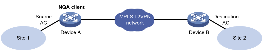
In each path quality analysis probe, the NQA client sends packets of a fixed size at a specific speed to the destination device for the specified probe duration.
For each type of path quality analysis operation, you can specify a list of packet sizes by using the frame-size command. The NQA client uses the listed packet sizes in turn to send packets. Packets per probe are of the same size.
Frame loss operation
1. The NQA client sends probe packets of the first listed packet size to the destination device at the initial sending speed for the first probe.
2. When the destination device receives the probe packets, it sends back response packets.
3. The NQA client calculates and records the frame loss ratio for the first probe by using the following formula:
Frame loss ratio = (sent packets – received packets) × 100 / sent packets
4. After the specified probe interval, the NQA client starts another probe to test the frame loss ratio by sending packets of the second listed packet size.
5. The process continues until all listed packet sizes are tested.
Throughput operation
1. The NQA client sends probe packets of the first listed packet size to the destination device at the initial sending speed for the first probe.
2. When the destination device receives the probe packets, it sends back response packets.
3. The NQA client calculates and records the frame loss ratio for the probe.
4. The NQA client adjusts the packet sending speed (based on the configured granularity) and sends the probe packets of the same size for another probe.
5. The client repeats steps 3 through 4 until it determines the maximum packet sending speed at which it can send the packets with an acceptable frame loss ratio. The acceptable frame loss ratio must not be higher than the specified maximum acceptable frame loss ratio.
The maximum packet sending speed is recorded as the throughput for the specific packet size.
6. The NQA client follows the same procedure to determine the throughput for subsequent packet sizes in the packet size list.
7. The process stops when the last listed packet size is tested.
Latency operation
1. The NQA client sends probe packets of the first listed packet size to the destination device at the initial sending speed for the first probe.
2. When the NQA client receives a response packet from the destination device, the client calculates the round-trip time (latency) for the packet.
3. When the first probe duration expires, the NQA client calculates the average latency for the first packet size by using the following formula:
Average latency = Sum of all latency values / sent packets
4. The NQA client starts another probe to test the latency for packets of the second listed packet size.
5. The process stops when the last listed packet size is tested.
Restrictions and guidelines
The display nqa history command does not display the results or statistics of path quality analysis operations. To view the results or statistics of path quality analysis operations, use the display nqa result or display nqa statistics command.
For path quality analysis operations and Y.1564 operations to start successfully, configure the source and destination IP addresses as follows:
· In a Layer 2 Ethernet, Layer 3 Ethernet, L2VPN, or L3VPN network, configure both source and destination IP addresses.
· In other networks, you must configure both of them or none of them. If they are configured, make sure the source and destination IP addresses are of the same IP version.
Configuring the path quality analysis operation parameters
1. Enter system view.
system-view
2. (Optional.) Configure the FTP server to which the NQA client uploads the operation results.
nqa report-ftp url url [ username username ] [ password { cipher | simple } string ]
By default, no FTP server is configured.
Only the path quality analysis operation supports uploading operation results to the FTP server.
3. Create an NQA operation and enter NQA operation view.
nqa entry admin-name operation-tag
4. Specify a path quality analysis operation type and enter its view. Choose the options to configure as needed:
¡ Specify the frame loss operation type.
type frame-loss
¡ Specify the throughput operation type.
type throughput
¡ Specify the latency operation type.
type latency
5. Specify the addresses and port numbers for the path quality analysis operation.
a. Specify the source IP address for the probe packets.
IPv4:
source ip ipv4-address
By default, the source IPv4 address is not specified.
IPv6:
source ipv6 ipv6-address
By default, the source IPv4 address is not specified.
b. Specify the destination IP address for the probe packets.
IPv4:
destination ip ipv4-address
By default, the destination IPv4 address is not specified.
IPv6:
destination ipv6 ipv6-address
By default, the destination IPv6 address is not specified.
c. Specify the source AC or source interface for the probe packets.
source interface interface-type interface-number [ service-instance instance-id ]
By default, the source AC or source interface is not specified.
The service-instance keyword is required for the operation in an L2VPN network.
The specified source interface must be up.
For more information about the AC interface, see VPLS in MPLS Configuration Guide.
d. Specify the egress interface for the probe packets.
out interface interface-type interface-number
By default, the egress interface is not specified.
This task is required when the client is a Layer 3 Ethernet gateway or an L3VPN gateway.
e. Specify the source port number for the probe packets.
source port port-number
By default , the source port number is 49184.
For the operation to succeed, make sure the specified port number is not used by any services on the device. As a best practice, use the default value.
f. Specify the destination port number for the probe packets.
destination port port-number
By default, the destination port number is 7.
g. Specify the source MAC address for the probe packets.
source mac mac-address
By default, the source MAC address for the probe packets is the MAC address of the egress port.
This task is required for the operation in a Layer 2 Ethernet and L2VPN network.
h. Specify the destination MAC address for the probe packets.
destination mac mac-address
By default, the destination MAC address is 0023-8900-0001.
This task is required for the operation in a Layer 2 Ethernet and L2VPN network.
6. Specify the basic parameters for the Y.1564 operations.
¡ (Optional.) Specify the description for the Y.1564 operation.
description text
By default, the description is not specified.
¡ Set the size of the probe packets.
frame-size size&<1-7>
By default, the probe packet size is 1518 bytes.
¡ Specify the initial packet sending speed.
speed init init-speed
By default, the initial frame sending speed is 100000 kbps.
The frame loss and latency operations use the specified initial packet sending speed for all probes.
The throughput operation starts the first probe at the specified initial packet sending speed and adjusts the speed according to the configured granularity for each subsequent probe.
¡ Specify the granularity for adjusting the packet sending speed.
speed granularity value
The default setting is 1000 kbps.
This command is available only in throughput operation view.
The throughput operation starts the first probe at the specified initial packet sending speed and adjusts the speed according to the configured granularity for each subsequent probe.
¡ Specify the maximum acceptable frame loss ratio.
allowed-loss-ratio ratio
By default, the maximum acceptable frame loss ratio is 1/10000.
This command is available only in throughput operation view.
¡ Set the ToS value in the IP header of the probe packets.
tos value
By default, the ToS value is 0.
7. (Optional.) Configure the probe parameters for the path quality analysis operation.
¡ Set the interval between consecutive probes.
probe interval interval
The default probe interval is 4 seconds.
¡ Specify the probe duration in seconds.
probe duration time
The default probe duration is 60 seconds.
¡ Set the probe timeout time.
probe timeout timeout
The default setting is 3000 milliseconds.
8. (Optional.) Specify the ID of the VLAN to which the probe packets belong.
vlan { vlan-id | s-vid vlan-id c-vid vlan-id }
By default, no VLAN ID is specified.
9. Specify the VPN instance where the operation is performed.
vpn-instance vpn-instance-name
By default, no VPN instance is specified.
This task is required for the operation in an L3VPN network.
10. (Optional.) Specify the 802.1p priority for the probe packets.
priority 8021p value
By default, the 802.1p priority of the probe packets is 0.
11. (Optional.) Enable the port exchange between the source port and destination port.
exchange-port enable
By default, the port exchange is disabled.
Configuring an RFC2544 operation group
You can bind multiple RFC2544 operations to a NQA RFC2544 operation group. By starting the operation group, you can start all the path quality analysis operations in the group.
After an RFC2544 operation group starts, the device performs operations in the group the one by one.
1. Enter system view.
system-view
2. Create an RFC2544 operation group and enter its view.
nqa rfc2544 group group-name
3. Bind an RFC2544 operation to the RFC2544 operation group.
bind nqa-entry admin-name operation-tag
By default, an RFC2544 operation group does not contain any RFC2544 operations.
You can repeat this command to bind multiple operations to the RFC2544 operation group.
Starting the path quality analysis operation
1. Enter system view.
system-view
2. Enter NQA operation view or RFC2544 operation group view.
¡ Enter NQA operation view.
nqa entry admin-name operation-tag
¡ Enter RFC2544 operation group view.
¡ nqa rfc2544 group group-name
3. Start the operation.
start
You can also configure the scheduling parameters to start the operation. For information about scheduling parameters, see "Scheduling the NQA operation on the NQA client."
Stopping the operation
1. Enter system view.
system-view
2. Enter NQA operation view or RFC2544 operation group view.
¡ Enter NQA operation view.
nqa entry admin-name operation-tag
¡ Enter RFC2544 operation group.
nqa rfc2544 group group-name
3. Stop the path quality analysis operation.
stop
Configuring optional parameters for the NQA operation
Restrictions and guidelines
Unless otherwise specified, the following optional parameters apply to all types of NQA operations.
The supported optional parameters might vary by NQA operation type. For more informatin, see the command reference.
The path quality analysis operations and Y.1564 operations support only the description, tos, and vpn-instance commands. For more information about these operations, see "Configuring the Y.1564 operation" and "Configuring path quality analysis operations."
Procedure
1. Enter system view.
system-view
2. Enter the view of an existing NQA operation.
nqa entry admin-name operation-tag
3. Specify an NQA operation type and enter its view.
type { dhcp | dlsw | dns | frame-loss | ftp | http | icmp-echo | icmp-jitter | latency | path-jitter | snmp | tcp | throughput | udp-echo | udp-jitter | udp-tracert | voice | y1564 }
4. Configure a description for the operation.
description text
By default, no description is configured.
5. Set the interval at which the NQA operation repeats.
frequency interval
For a voice or path jitter operation, the default setting is 60000 milliseconds.
For other types of operations, the default setting is 0 milliseconds, and only one operation is performed.
When the interval expires, but the operation is not completed or is not timed out, the next operation does not start.
6. Specify the probe times.
probe count times
In an UDP tracert operation, the NQA client performs three probes to each hop to the destination by default.
In other types of operations, the NQA client performs one probe to the destination per operation by default.
This command is not available for the voice and path jitter operations. Each of these operations performs only one probe.
7. Set the probe timeout time.
probe timeout timeout
The default setting is 3000 milliseconds.
8. Set the maximum number of hops that the probe packets can traverse.
ttl value
The default setting is 30 for probe packets of the UDP tracert operation, and is 20 for probe packets of other types of operations.
9. Set the ToS value in the IP header of the probe packets.
tos value
The default setting is 0.
10. Enable the routing table bypass feature.
route-option bypass-route
By default, the routing table bypass feature is disabled.
This command does not take effect if the destination address of the NQA operation is an IPv6 address.
11. Specify the VPN instance where the operation is performed.
vpn-instance vpn-instance-name
By default, the operation is performed on the public network.
Configuring the collaboration feature
About this task
Collaboration is implemented by associating a reaction entry of an NQA operation with a track entry. The reaction entry monitors the NQA operation. If the number of operation failures reaches the specified threshold, the configured action is triggered.
Restrictions and guidelines
The collaboration feature is not available for the following types of operations:
· ICMP jitter operation.
· UDP jitter operation.
· UDP tracert operation.
· Voice operation.
· Path jitter operation.
· Path quality analysis operations.
· Y.1564 operation.
Procedure
1. Enter system view.
system-view
2. Enter the view of an existing NQA operation.
nqa entry admin-name operation-tag
3. Configure a reaction entry.
reaction item-number checked-element probe-fail threshold-type consecutive consecutive-occurrences action-type trigger-only
You cannot modify the content of an existing reaction entry.
4. Return to system view.
quit
5. Associate Track with NQA.
For information about the configuration, see High Availability Configuration Guide.
6. Associate Track with an application module.
For information about the configuration, see High Availability Configuration Guide.
Configuring threshold monitoring
About this task
This feature allows you to monitor the NQA operation running status.
An NQA operation supports the following threshold types:
· average—If the average value for the monitored performance metric either exceeds the upper threshold or goes below the lower threshold, a threshold violation occurs.
· accumulate—If the total number of times that the monitored performance metric is out of the specified value range reaches or exceeds the specified threshold, a threshold violation occurs.
· consecutive—If the number of consecutive times that the monitored performance metric is out of the specified value range reaches or exceeds the specified threshold, a threshold violation occurs.
Threshold violations for the average or accumulate threshold type are determined on a per NQA operation basis. The threshold violations for the consecutive type are determined from the time the NQA operation starts.
The following actions might be triggered:
· none—NQA displays results only on the terminal screen. It does not send traps to the NMS.
· trap-only—NQA displays results on the terminal screen, and meanwhile it sends traps to the NMS.
To send traps to the NMS, the NMS address must be specified by using the snmp-agent target-host command. For more information about the command, see Network Management and Monitoring Command Reference.
· trigger-only—NQA displays results on the terminal screen, and meanwhile triggers other modules for collaboration.
In a reaction entry, configure a monitored element, a threshold type, and an action to be triggered to implement threshold monitoring.
The state of a reaction entry can be invalid, over-threshold, or below-threshold.
· Before an NQA operation starts, the reaction entry is in invalid state.
· If the threshold is violated, the state of the entry is set to over-threshold. Otherwise, the state of the entry is set to below-threshold.
Restrictions and guidelines
The threshold monitoring feature is not available for the following types of operations:
· Path jitter operation.
· Path quality analysis operations.
· Y.1564 operation.
Procedure
1. Enter system view.
system-view
2. Enter the view of an existing NQA operation.
nqa entry admin-name operation-tag
3. Enable sending traps to the NMS when specific conditions are met.
reaction trap { path-change | probe-failure consecutive-probe-failures | test-complete | test-failure [ accumulate-probe-failures ] }
By default, no traps are sent to the NMS.
The ICMP jitter, UDP jitter, and voice operations support only the test-complete keyword.
The following parameters are not available for the UDP tracert operation:
¡ The probe-failure consecutive-probe-failures option.
¡ The accumulate-probe-failures argument.
4. Configure threshold monitoring. Choose the options to configure as needed:
¡ Monitor the operation duration.
reaction item-number checked-element probe-duration threshold-type { accumulate accumulate-occurrences | average | consecutive consecutive-occurrences } threshold-value upper-threshold lower-threshold [ action-type { none | trap-only } ]
This reaction entry is not supported in the ICMP jitter, UDP jitter, UDP tracert, or voice operations
¡ Monitor failure times.
reaction item-number checked-element probe-fail threshold-type { accumulate accumulate-occurrences | consecutive consecutive-occurrences } [ action-type { none | trap-only } ]
This reaction entry is not supported in the ICMP jitter, UDP jitter, UDP tracert, or voice operations.
¡ Monitor the round-trip time.
reaction item-number checked-element rtt threshold-type { accumulate accumulate-occurrences | average } threshold-value upper-threshold lower-threshold [ action-type { none | trap-only } ]
Only the ICMP jitter, UDP jitter, and voice operations support this reaction entry.
¡ Monitor packet loss.
reaction item-number checked-element packet-loss threshold-type accumulate accumulate-occurrences [ action-type { none | trap-only } ]
Only the ICMP jitter, UDP jitter, and voice operations support this reaction entry.
¡ Monitor the one-way jitter.
reaction item-number checked-element { jitter-ds | jitter-sd } threshold-type { accumulate accumulate-occurrences | average } threshold-value upper-threshold lower-threshold [ action-type { none | trap-only } ]
Only the ICMP jitter, UDP jitter, and voice operations support this reaction entry.
¡ Monitor the one-way delay.
reaction item-number checked-element { owd-ds | owd-sd } threshold-value upper-threshold lower-threshold
Only the ICMP jitter, UDP jitter, and voice operations support this reaction entry.
¡ Monitor the ICPIF value.
reaction item-number checked-element icpif threshold-value upper-threshold lower-threshold [ action-type { none | trap-only } ]
Only the voice operation supports this reaction entry.
¡ Monitor the MOS value.
reaction item-number checked-element mos threshold-value upper-threshold lower-threshold [ action-type { none | trap-only } ]
Only the voice operation supports this reaction entry.
The DNS operation does not support the action of sending trap messages. For the DNS operation, the action type can only be none.
Configuring the NQA statistics collection feature
About this task
NQA forms statistics within the same collection interval as a statistics group. To display information about the statistics groups, use the display nqa statistics command.
When the maximum number of statistics groups is reached, the NQA client deletes the oldest statistics group to save a new one.
A statistics group is automatically deleted when its hold time expires.
Restrictions and guidelines
The NQA statistics collection feature is not available for the following types of operations:
· UDP tracert operation.
· Path quality analysis operations.
· Y.1564 operation.
If you use the frequency command to set the interval to 0 milliseconds for an NQA operation, NQA does not generate any statistics group for the operation.
Procedure
1. Enter system view.
system-view
2. Enter the view of an existing NQA operation.
nqa entry admin-name operation-tag
3. Set the statistics collection interval.
statistics interval interval
The default setting is 60 minutes.
4. Set the maximum number of statistics groups that can be saved.
statistics max-group number
By default, the NQA client can save a maximum of two statistics groups for an operation.
To disable the NQA statistics collection feature, set the number argument to 0.
5. Set the hold time of statistics groups.
statistics hold-time hold-time
The default setting is 120 minutes.
Configuring the saving of NQA history records
About this task
This task enables the NQA client to save NQA history records. You can use the display nqa history command to display the NQA history records.
Restrictions and guidelines
The NQA history record saving feature is not available for the following types of operations:
· ICMP jitter operation.
· UDP jitter operation.
· Voice operation.
· Path jitter operation.
· Path quality analysis operations.
· Y.1564 operation.
Procedure
1. Enter system view.
system-view
2. Enter the view of an existing NQA operation.
nqa entry admin-name operation-tag
3. Enable the saving of history records for the NQA operation.
history-record enable
By default, this feature is enabled only for the UDP tracert operation.
4. Set the lifetime of history records.
history-record keep-time keep-time
The default setting is 120 minutes.
A record is deleted when its lifetime is reached.
5. Set the maximum number of history records that can be saved.
history-record number number
The default setting is 50.
When the maximum number of history records is reached, the system will delete the oldest record to save a new one.
Scheduling the NQA operation on the NQA client
About this task
The NQA operation runs between the specified start time and end time (the start time plus operation duration). If the specified start time is ahead of the system time, the operation starts immediately. If both the specified start and end time are ahead of the system time, the operation does not start. To display the current system time, use the display clock command.
Restrictions and guidelines
You cannot enter the operation type view or the operation view of a scheduled NQA operation.
A system time adjustment does not affect started or completed NQA operations. It affects only the NQA operations that have not started.
The NQA operation scheduling is not available for path quality analysis operations and Y.1564 operations.
Procedure
1. Enter system view.
system-view
2. Specify the scheduling parameters for an NQA operation.
nqa schedule admin-name operation-tag start-time { hh:mm:ss [ yyyy/mm/dd | mm/dd/yyyy ] | now } lifetime { lifetime | forever } [ recurring ]
Configuring NQA templates on the NQA client
Restrictions and guidelines
Some operation parameters for an NQA template can be specified by the template configuration or the feature that uses the template. When both are specified, the parameters in the template configuration take effect.
NQA template tasks at a glance
To configure NQA templates, perform the following tasks:
1. Perform at least one of the following tasks:
¡ Configuring the ARP template
¡ Configuring the ICMP template
¡ Configuring the IMAP template
¡ Configuring the DNS template
¡ Configuring the POP3 template
¡ Configuring the SMTP template
¡ Configuring the TCP template
¡ Configuring the TCP half open template
¡ Configuring the UDP template
¡ Configuring the HTTP template
¡ Configuring the HTTPS template
¡ Configuring the FTP template
¡ Configuring the RADIUS template
¡ Configuring the SNMP template
¡ Configuring the SSL template
2. (Optional.) Configuring optional parameters for the NQA template
Configuring the ARP template
About this task
A feature that uses the ARP template performs the ARP operation to test whether the ARP service is available on the destination device.
In the ARP operation, the NQA client sends an ARP request to the destination device. If the client receives an ARP reply, it determines that the ARP service is available on the destination device.
Procedure
1. Enter system view.
system-view
2. Create an ARP template and enter its view.
nqa template arp name
3. Specify the destination IP address to be used as the target IP for ARP requests.
destination ip ip-address
By default, no destination IP address is configured.
4. (Optional.) Specify the source IP address to be used as the sender IP for ARP requests.
source ip ip-address
By default, the primary IP address of the output interface is used as the source IP address of ARP packets.
The specified source IP address must be the IP address of a local interface, and the interface must be up. Otherwise, no probe packets can be sent out.
Configuring the ICMP template
About this task
A feature that uses the ICMP template performs the ICMP operation to measure the reachability of a destination device. The ICMP template is supported on both IPv4 and IPv6 networks.
Procedure
1. Enter system view.
system-view
2. Create an ICMP template and enter its view.
nqa template icmp name
3. Specify the destination address for the operation.
IPv4:
destination ip ip-address
IPv6:
destination ipv6 ipv6-address
By default, no destination IP address is configured.
4. Specify the source IP address for ICMP echo requests. Choose one option as needed:
¡ Use the IP address of the specified interface as the source IP address.
source interface interface-type interface-number
By default, the primary IP address of the output interface is used as the source IP address of ICMP echo requests.
The specified source interface must be up.
¡ Specify the source IPv4 address.
source ip ip-address
By default, the primary IPv4 address of the output interface is used as the source IPv4 address of ICMP echo requests.
The specified source IPv4 address must be the IPv4 address of a local interface, and the interface must be up. Otherwise, no probe packets can be sent out.
¡ Specify the source IPv6 address.
source ipv6 ipv6-address
By default, the primary IPv6 address of the output interface is used as the source IPv6 address of ICMP echo requests.
The specified source IPv6 address must be the IPv6 address of a local interface, and the interface must be up. Otherwise, no probe packets can be sent out.
5. Specify the next hop IP address for ICMP echo requests.
IPv4:
next-hop ip ip-address
IPv6:
next-hop ipv6 ipv6-address
By default, no IP address of the next hop is configured.
6. Configure the probe result sending on a per-probe basis.
reaction trigger per-probe
By default, the probe result is sent to the feature that uses the template after three consecutive failed or successful probes.
If you execute the reaction trigger per-probe and reaction trigger probe-pass commands multiple times, the most recent configuration takes effect.
If you execute the reaction trigger per-probe and reaction trigger probe-fail commands multiple times, the most recent configuration takes effect.
7. (Optional.) Set the payload size for each ICMP request.
data-size size
The default setting is 100 bytes.
8. (Optional.) Specify the payload fill string for ICMP echo requests.
data-fill string
The default payload fill string is the hexadecimal string 00010203040506070809.
Configuring the IMAP template
About this task
A feature that uses the IMAP template performs the IMAP operation to determine the availability of the IMAP service on the IMAP server.
Before you perform an IMAP operation, enable the IMAP Server service on the IMAP server and configure related settings, including the login username, password, and mailbox name.
Procedure
1. Enter system view.
system-view
2. Create an IMAP template and enter IMAP template view.
nqa template imap name
3. Specify the destination IP address for the probe packets.
IPv4:
destination ip ip-address
IPv6:
destination ipv6 ipv6-address
By default, no destination address is specified.
4. Specify the destination port number for the probe packets.
destination port port-number
By default, the destination port number is 143.
5. Specify the source IP address for the probe packets.
IPv4:
source ip ip-address
By default, the source IPv4 address of the probe packets is the primary IPv4 address of the output interface.
The source IPv4 address must be the IPv4 address of a local interface, and the interface must be up. Otherwise, no probe packets can be sent out.
IPv6:
source ipv6 ipv6-address
By default, the source IPv6 address of the probe packets is the primary IPv6 address of the output interface.
The source IPv6 address must be the IPv6 address of a local interface, and the interface must be up. Otherwise, no probe packets can be sent out.
6. Specify the login username.
username username
By default, no login username is specified.
7. Specify the login password.
password { cipher | simple } string
By default, no login password is specified.
8. Specify the mailbox name.
mailbox mailbox-name
By default, mailbox INBOX is used.
Configuring the DNS template
About this task
A feature that uses the DNS template performs the DNS operation to determine the status of the server. The DNS template is supported on both IPv4 and IPv6 networks.
In DNS template view, you can specify the address expected to be returned. If the returned IP addresses include the expected address, the DNS server is valid and the operation succeeds. Otherwise, the operation fails.
Prerequisites
Create a mapping between the domain name and an address before you perform the DNS operation. For information about configuring the DNS server, see documents about the DNS server configuration.
Procedure
1. Enter system view.
system-view
2. Create a DNS template and enter DNS template view.
nqa template dns name
3. Specify the destination IP address for the probe packets.
IPv4:
destination ip ip-address
IPv6:
destination ipv6 ipv6-address
By default, no destination address is specified.
4. Specify the destination port number for the probe packets.
destination port port-number
By default, the destination port number is 53.
5. Specify the source IP address for the probe packets.
IPv4:
source ip ip-address
By default, the source IPv4 address of the probe packets is the primary IPv4 address of their output interface.
The source IPv4 address must be the IPv4 address of a local interface, and the interface must be up. Otherwise, no probe packets can be sent out.
IPv6:
source ipv6 ipv6-address
By default, the source IPv6 address of the probe packets is the primary IPv6 address of their output interface.
The source IPv6 address must be the IPv6 address of a local interface, and the interface must be up. Otherwise, no probe packets can be sent out.
6. Specify the source port number for the probe packets.
source port port-number
By default, the system randomly picks an unused port as the source port when the operation starts.
For the operation to succeed, make sure the specified port number is not used by any services on the device. As a best practice, use the default value.
7. Specify the domain name to be translated.
resolve-target domain-name
By default, no domain name is specified.
8. Specify the domain name resolution type.
resolve-type { A | AAAA }
By default, the type is type A.
A type A query resolves a domain name to a mapped IPv4 address, and a type AAAA query to a mapped IPv6 address.
9. (Optional.) Specify the IP address that is expected to be returned.
IPv4:
expect ip ip-address
IPv6:
expect ipv6 ipv6-address
By default, no expected IP address is specified.
Configuring the POP3 template
About this task
A feature that uses the POP3 template performs the POP3 operation to determine the availability of the POP3 service on the POP3 server.
Before you perform a POP3 operation, enable the POP3 Server on the POP3 server and configure related settings, including the login username and password.
Procedure
1. Enter system view.
system-view
2. Create a POP3 template and enter POP3 template view.
nqa template pop3 name
3. Specify the destination IP address for the probe packets.
IPv4:
destination ip ip-address
IPv6:
destination ipv6 ipv6-address
By default, no destination IP address is specified.
4. Specify the destination port number for the probe packets.
destination port port-number
By default, the destination port number is 110.
5. Specify the source IP address for the probe packets.
IPv4:
source ip ip-address
By default, the source IPv4 address of the probe packets is the primary IPv4 address of their output interface.
The source IPv4 address must be the IPv4 address of a local interface, and the interface must be up. Otherwise, no probe packets can be sent out.
IPv6:
source ipv6 ipv6-address
By default, the source IPv6 address of the probe packets is the primary IPv6 address of their output interface.
The source IPv6 address must be the IPv6 address of a local interface, and the interface must be up. Otherwise, no probe packets can be sent out.
6. Specify the login username.
username username
By default, no login username is specified.
7. Specify the login password.
password { cipher | simple } string
By default, no login password is specified.
Configuring the SMTP template
About this task
A feature that uses the SMTP template performs the SMTP operation to determine the availability of the SMTP service on the SMTP server.
Procedure
1. Enter system view.
system-view
2. Create a SMTP template and enter SMTP template view.
nqa template smtp name
3. Specify the destination IP address for the probe packets.
IPv4:
destination ip ip-address
IPv6:
destination ipv6 ipv6-address
By default, no destination IP address is specified.
4. Specify the destination port number for the probe packets.
destination port port-number
By default, the destination port number is 110.
5. Specify the source IP address for the probe packets.
IPv4:
source ip ip-address
By default, the primary IPv4 address of the output interface is used as the source IPv4 address of the probe packets.
The source IPv4 address must be the IPv4 address of a local interface, and the interface must be up. Otherwise, no probe packets can be sent out.
IPv6:
source ipv6 ipv6-address
By default, the primary IPv6 address of the output interface is used as the source IPv6 address of the probe packets.
The source IPv6 address must be the IPv6 address of a local interface, and the interface must be up. Otherwise, no probe packets can be sent out.
Configuring the TCP template
About this task
A feature that uses the TCP template performs the TCP operation to test whether the NQA client can establish a TCP connection to a specific port on the server.
In TCP template view, you can specify the expected data to be returned. If you do not specify the expected data, the TCP operation tests only whether the client can establish a TCP connection to the server.
The TCP operation requires both the NQA server and the NQA client. Before you perform a TCP operation, configure a TCP listening service on the NQA server. For more information about the TCP listening service configuration, see "Configuring the NQA server."
Procedure
1. Enter system view.
system-view
2. Create a TCP template and enter its view.
nqa template tcp name
3. Specify the destination IP address for the probe packets.
IPv4:
destination ip ip-address
IPv6:
destination ipv6 ipv6-address
By default, no destination IP address is specified.
The destination address must be the same as the IP address of the TCP listening service configured on the NQA server.
4. Specify the destination port number for the operation.
destination port port-number
By default, no destination port number is specified.
The destination port number must be the same as the port number of the TCP listening service on the NQA server.
5. Specify the source IP address for the probe packets.
IPv4:
source ip ip-address
By default, the primary IPv4 address of the output interface is used as the source IPv4 address of the probe packets.
The source IP address must be the IPv4 address of a local interface, and the interface must be up. Otherwise, no probe packets can be sent out.
IPv6:
source ipv6 ipv6-address
By default, the primary IPv6 address of the output interface is used as the source IPv6 address of the probe packets.
The source IPv6 address must be the IPv6 address of a local interface, and the interface must be up. Otherwise, no probe packets can be sent out.
6. (Optional.) Specify the payload fill string for the probe packets.
data-fill string
The default payload fill string is the hexadecimal string 00010203040506070809.
7. (Optional.) Configure the expected data.
expect data expression [ offset number ]
By default, no expected data is configured.
The NQA client performs expect data check only when you configure both the data-fill and expect-data commands.
Configuring the TCP half open template
About this task
A feature that uses the TCP half open template performs the TCP half open operation to test whether the TCP service is available on the server. The TCP half open operation is used when the feature cannot get a response from the TCP server through an existing TCP connection.
In the TCP half open operation, the NQA client sends a TCP ACK packet to the server. If the client receives an RST packet, it considers that the TCP service is available on the server.
Procedure
1. Enter system view.
system-view
2. Create a TCP half open template and enter its view.
nqa template tcphalfopen name
3. Specify the destination IP address of the operation.
IPv4:
destination ip ip-address
IPv6:
destination ipv6 ipv6-address
By default, no destination IP address is specified.
The destination address must be the same as the IP address of the TCP listening service configured on the NQA server.
4. Specify the source IP address for the probe packets.
IPv4:
source ip ip-address
By default, the primary IPv4 address of the output interface is used as the source IPv4 address of the probe packets.
The source IPv4 address must be the IPv4 address of a local interface, and the interface must be up. Otherwise, no probe packets can be sent out.
IPv6:
source ipv6 ipv6-address
By default, the primary IPv6 address of the output interface is used as the source IPv6 address of the probe packets.
The source IPv6 address must be the IPv6 address of a local interface, and the interface must be up. Otherwise, no probe packets can be sent out.
5. Specify the next hop IP address for the probe packets.
IPv4:
next-hop ip ip-address
IPv6:
next-hop ipv6 ipv6-address
By default, the IP address of the next hop is configured.
6. Configure the probe result sending on a per-probe basis.
reaction trigger per-probe
By default, the probe result is sent to the feature that uses the template after three consecutive failed or successful probes.
If you execute the reaction trigger per-probe and reaction trigger probe-pass commands multiple times, the most recent configuration takes effect.
If you execute the reaction trigger per-probe and reaction trigger probe-fail commands multiple times, the most recent configuration takes effect.
Configuring the UDP template
About this task
A feature that uses the UDP template performs the UDP operation to test the following items:
· Reachability of a specific port on the NQA server.
· Availability of the requested service on the NQA server.
In UDP template view, you can specify the expected data to be returned. If you do not specify the expected data, the UDP operation tests only whether the client can receive the response packet from the server.
The UDP operation requires both the NQA server and the NQA client. Before you perform a UDP operation, configure a UDP listening service on the NQA server. For more information about the UDP listening service configuration, see "Configuring the NQA server."
Procedure
1. Enter system view.
system-view
2. Create a UDP template and enter its view.
nqa template udp name
3. Specify the destination IP address of the operation.
IPv4:
destination ip ip-address
IPv6:
destination ipv6 ipv6-address
By default, no destination IP address is specified.
The destination address must be the same as the IP address of the UDP listening service configured on the NQA server.
4. Specify the destination port number for the operation.
destination port port-number
By default, no destination port number is specified.
The destination port number must be the same as the port number of the UDP listening service on the NQA server.
5. Specify the source IP address for the probe packets.
IPv4:
source ip ip-address
By default, the primary IPv4 address of the output interface is used as the source IPv4 address of the probe packets.
The source IP address must be the IPv4 address of a local interface, and the interface must be up. Otherwise, no probe packets can be sent out.
IPv6:
source ipv6 ipv6-address
By default, the primary IPv6 address of the output interface is used as the source IPv6 address of the probe packets.
The source IPv6 address must be the IPv6 address of a local interface, and the interface must be up. Otherwise, no probe packets can be sent out.
6. Specify the payload fill string for the probe packets.
data-fill string
The default payload fill string is the hexadecimal string 00010203040506070809.
7. (Optional.) Set the payload size for the probe packets.
data-size size
The default setting is 100 bytes.
8. (Optional.) Configure the expected data.
expect data expression [ offset number ]
By default, no expected data is configured.
Expected data check is performed only when both the data-fill command and the expect data command are configured.
Configuring the HTTP template
About this task
A feature that uses the HTTP template performs the HTTP operation to measure the time it takes the NQA client to obtain data from an HTTP server.
The expected data is checked only when the data is configured and the HTTP response contains the Content-Length field in the HTTP header.
The status code of the HTTP packet is a three-digit field in decimal notation, and it includes the status information for the HTTP server. The first digit defines the class of response.
Prerequisites
Before you perform the HTTP operation, you must configure the HTTP server.
Procedure
1. Enter system view.
system-view
2. Create an HTTP template and enter its view.
nqa template http name
3. Specify the destination URL for the HTTP template.
url url
By default, no destination URL is specified for an HTTP template.
Enter the URL in one of the following formats:
¡ http://host/resource
¡ http://host:port/resource
4. Specify an HTTP login username.
username username
By default, no HTTP login username is specified.
5. Specify an HTTP login password.
password { cipher | simple } string
By default, no HTTP login password is specified.
6. Specify the HTTP version.
version { v1.0 | v1.1 }
By default, HTTP 1.0 is used.
7. Specify the HTTP operation type.
operation { get | post | raw }
By default, the HTTP operation type is get.
If you set the operation type to raw, the client pads the content configured in raw request view to the HTTP request to send to the HTTP server.
8. Configure the content of the HTTP raw request.
a. Enter raw request view.
raw-request
Every time you enter raw request view, the previously configured raw request content is cleared.
b. Enter or paste the request content.
By default, no request content is configured.
To ensure successful operations, make sure the request content does not contain command aliases configured by using the alias command. For more information about the alias command, see CLI commands in Fundamentals Command Reference.
c. Return to HTTP template view.
quit
The system automatically saves the configuration in raw request view before it returns to HTTP template view.
This step is required only when the operation type is set to raw.
9. Specify the source IP address for the probe packets.
IPv4:
source ip ip-address
By default, the primary IPv4 address of the output interface is used as the source IPv4 address of the probe packets.
The source IPv4 address must be the IPv4 address of a local interface, and the interface must be up. Otherwise, no probe packets can be sent out.
IPv6:
source ipv6 ipv6-address
By default, the primary IPv6 address of the output interface is used as the source IPv6 address of the probe packets.
The source IPv6 address must be the IPv6 address of a local interface, and the interface must be up. Otherwise, no probe packets can be sent out.
10. (Optional.) Configure the expected status codes.
expect status status-list
By default, no expected status code is configured.
11. (Optional.) Configure the expected data.
expect data expression [ offset number ]
By default, no expected data is configured.
Configuring the HTTPS template
About this task
A feature that uses the HTTPS template performs the HTTPS operation to measure the time it takes for the NQA client to obtain data from an HTTPS server.
The expected data is checked only when the expected data is configured and the HTTPS response contains the Content-Length field in the HTTPS header.
The status code of the HTTPS packet is a three-digit field in decimal notation, and it includes the status information for the HTTPS server. The first digit defines the class of response.
Prerequisites
Before you perform the HTTPS operation, configure the HTTPS server and the SSL client policy for the SSL client. For information about configuring SSL client policies, see Security Configuration Guide.
Procedure
1. Enter system view.
system-view
2. Create an HTTPS template and enter its view.
nqa template https name
3. Specify the destination URL for the HTTPS template.
url url
By default, no destination URL is specified for an HTTPS template.
Enter the URL in one of the following formats:
¡ https://host/resource
¡ https://host:port/resource
4. Specify an HTTPS login username.
username username
By default, no HTTPS login username is specified.
5. Specify an HTTPS login password.
password { cipher | simple } string
By default, no HTTPS login password is specified.
6. Specify an SSL client policy.
ssl-client-policy policy-name
By default, no SSL client policy is specified.
7. Specify the HTTPS version.
version { v1.0 | v1.1 }
By default, HTTPS 1.0 is used.
8. Specify the HTTPS operation type.
operation { get | post | raw }
By default, the HTTPS operation type is get.
If you set the operation type to raw, the client pads the content configured in raw request view to the HTTPS request to send to the HTTPS server.
9. Configure the content of the HTTPS raw request.
a. Enter raw request view.
raw-request
Every time you enter raw request view, the previously configured raw request content is cleared.
b. Enter or paste the request content.
By default, no request content is configured.
To ensure successful operations, make sure the request content does not contain command aliases configured by using the alias command. For more information about the alias command, see CLI commands in Fundamentals Command Reference.
c. Return to HTTPS template view.
quit
The system automatically saves the configuration in raw request view before it returns to HTTPS template view.
This step is required only when the operation type is set to raw.
10. Specify the source IP address for the probe packets.
IPv4:
source ip ip-address
By default, the primary IPv4 address of the output interface is used as the source IPv4 address of the probe packets.
The source IP address must be the IPv4 address of a local interface, and the interface must be up. Otherwise, no probe packets can be sent out.
IPv6:
source ipv6 ipv6-address
By default, the primary IPv6 address of the output interface is used as the source IPv6 address of the probe packets.
The source IPv6 address must be the IPv6 address of a local interface, and the interface must be up. Otherwise, no probe packets can be sent out.
11. (Optional.) Configure the expected data.
expect data expression [ offset number ]
By default, no expected data is configured.
12. (Optional.) Configure the expected status codes.
expect status status-list
By default, no expected status code is configured.
Configuring the FTP template
About this task
A feature that uses the FTP template performs the FTP operation. The operation measures the time it takes the NQA client to transfer a file to or download a file from an FTP server.
Configure the username and password for the FTP client to log in to the FTP server before you perform an FTP operation. For information about configuring the FTP server, see Fundamentals Configuration Guide.
Procedure
1. Enter system view.
system-view
2. Create an FTP template and enter its view.
nqa template ftp name
3. Specify an FTP login username.
username username
By default, no FTP login username is specified.
4. Specify an FTP login password.
password { cipher | simple } sting
By default, no FTP login password is specified.
5. Specify the source IP address for the probe packets.
IPv4:
source ip ip-address
By default, the primary IPv4 address of the output interface is used as the source IPv4 address of the probe packets.
The source IP address must be the IPv4 address of a local interface, and the interface must be up. Otherwise, no probe packets can be sent out.
IPv6:
source ipv6 ipv6-address
By default, the primary IPv6 address of the output interface is used as the source IPv6 address of the probe packets.
The source IPv6 address must be the IPv6 address of a local interface, and the interface must be up. Otherwise, no probe packets can be sent out.
6. Set the data transmission mode.
mode { active | passive }
The default mode is active.
7. Specify the FTP operation type.
operation { get | put }
By default, the FTP operation type is get, which means obtaining files from the FTP server.
8. Specify the destination URL for the FTP template.
url url
By default, no destination URL is specified for an FTP template.
Enter the URL in one of the following formats:
¡ ftp://host/filename.
¡ ftp://host:port/filename.
When you perform the get operation, the file name is required.
When you perform the put operation, the filename argument does not take effect, even if it is specified. The file name for the put operation is determined by using the filename command.
9. Specify the name of a file to be transferred.
filename filename
By default, no file is specified.
This task is required only for the put operation.
The configuration does not take effect for the get operation.
Configuring the RADIUS template
About this task
A feature that uses the RADIUS template performs the RADIUS authentication operation to check the availability of the authentication service on the RADIUS server.
The RADIUS authentication operation workflow is as follows:
1. The NQA client sends an authentication request (Access-Request) to the RADIUS server. The request includes the username and the password. The password is encrypted by using the MD5 algorithm and the shared key.
2. The RADIUS server authenticates the username and password.
¡ If the authentication succeeds, the server sends an Access-Accept packet to the NQA client.
¡ If the authentication fails, the server sends an Access-Reject packet to the NQA client.
3. The NQA client determines the availability of the authentication service on the RADIUS server based on the response packet it received:
¡ If an Access-Accept packet is received, the authentication service is available on the RADIUS server.
¡ If an Access-Reject packet is received, the authentication service is not available on the RADIUS server.
Prerequisites
Before you configure the RADIUS template, specify a username, password, and shared key on the RADIUS server. For more information about configuring the RADIUS server, see AAA in BRAS Services Configuration Guide.
Procedure
1. Enter system view.
system-view
2. Create a RADIUS template and enter its view.
nqa template radius name
3. Specify the destination IP address of the operation.
IPv4:
destination ip ip-address
IPv6:
destination ipv6 ipv6-address
By default, no destination IP address is specified.
4. Specify the destination port number for the operation.
destination port port-number
By default, the destination port number is 1812.
5. Specify a username.
username username
By default, no username is specified.
6. Specify a password.
password { cipher | simple } string
By default, no password is specified.
7. Specify a shared key for secure RADIUS authentication.
key { cipher | simple } string
By default, no shared key is specified for RADIUS authentication.
8. Specify the source IP address for the probe packets.
IPv4:
source ip ip-address
By default, the primary IPv4 address of the output interface is used as the source IPv4 address of the probe packets.
The source IP address must be the IPv4 address of a local interface, and the interface must be up. Otherwise, no probe packets can be sent out.
IPv6:
source ipv6 ipv6-address
By default, the primary IPv6 address of the output interface is used as the source IPv6 address of the probe packets.
The source IPv6 address must be the IPv6 address of a local interface, and the interface must be up. Otherwise, no probe packets can be sent out.
Configuring the SNMP template
About this task
A feature that uses the SNMP template performs the SNMP operation to determine the availability of the SNMP service on an SNMP agent.
Procedure
1. Enter system view.
system-view
2. Create an SNMP template and enter SNMP template view.
nqa template snmp name
3. Specify the destination IP address of the operation.
IPv4:
destination ip ip-address
IPv6:
destination ipv6 ipv6-address
By default, no destination IP address is specified.
4. Specify the destination port number for the probe packets.
destination port port-number
The default destination port number is 161.
5. Specify the source IP address for the probe packets.
IPv4:
source ip ip-address
By default, the primary IPv4 address of the output interface is used as the source IPv4 address of the probe packets.
The source IP address must be the IPv4 address of a local interface, and the interface must be up. Otherwise, no probe packets can be sent out.
IPv6:
source ipv6 ipv6-address
By default, the primary IPv6 address of the output interface is used as the source IPv6 address of the probe packets.
The source IPv6 address must be the IPv6 address of a local interface, and the interface must be up. Otherwise, no probe packets can be sent out.
6. Specify the community name carried in the SNMPv1 and SNMPv2c packets.
community read { cipher | simple } community-name
By default, the SNMP template uses community name public.
Make sure the specified community name is the same as the community name configured on the SNMP agent.
Configuring the SSL template
About this task
A feature that uses the SSL template performs the SSL operation to measure the time required to establish an SSL connection to an SSL server.
Prerequisites
Before you configure the SSL template, you must configure the SSL client policy. For information about configuring SSL client policies, see Security Configuration Guide.
Procedure
1. Enter system view.
system-view
2. Create an SSL template and enter its view.
nqa template ssl name
3. Specify the destination IP address of the operation.
IPv4:
destination ip ip-address
IPv6:
destination ipv6 ipv6-address
By default, no destination IP address is specified.
4. Specify the destination port number for the operation.
destination port port-number
By default, the destination port number is not specified.
5. Specify an SSL client policy.
ssl-client-policy policy-name
By default, no SSL client policy is specified.
6. Specify the source IP address for the probe packets.
IPv4:
source ip ip-address
By default, the primary IPv4 address of the output interface is used as the source IPv4 address of the probe packets.
The source IP address must be the IPv4 address of a local interface, and the interface must be up. Otherwise, no probe packets can be sent out.
IPv6:
source ipv6 ipv6-address
By default, the primary IPv6 address of the output interface is used as the source IPv6 address of the probe packets.
The source IPv6 address must be the IPv6 address of a local interface, and the interface must be up. Otherwise, no probe packets can be sent out.
Configuring optional parameters for the NQA template
Restrictions and guidelines
Unless otherwise specified, the following optional parameters apply to all types of NQA templates.
The parameter settings take effect only on the current NQA template.
Procedure
1. Enter system view.
system-view
2. Enter the view of an existing NQA template.
nqa template { arp | dns | ftp | http | https | icmp | imap | pop3 | smtp | snmp | ssl | tcp | tcphalfopen | udp } name
3. Configure a description.
description text
By default, no description is configured.
4. Set the interval at which the NQA operation repeats.
frequency interval
The default setting is 5000 milliseconds.
If the operation is not completed when the interval expires, the next operation does not start.
5. Set the probe timeout time.
probe timeout timeout
The default setting is 3000 milliseconds.
6. Set the TTL for the probe packets.
ttl value
The default setting is 20.
This command is not available for the ARP template.
7. Set the ToS value in the IP header of the probe packets.
tos value
The default setting is 0.
This command is not available for the ARP template.
8. Specify the VPN instance where the operation is performed.
vpn-instance vpn-instance-name
By default, the operation is performed on the public network.
9. Set the number of consecutive successful probes to determine a successful operation event.
reaction trigger probe-pass count
The default setting is 3.
If the number of consecutive successful probes for an NQA operation is reached, the NQA client notifies the feature that uses the template of the successful operation event.
10. Set the number of consecutive probe failures to determine an operation failure.
reaction trigger probe-fail count
The default setting is 3.
If the number of consecutive probe failures for an NQA operation is reached, the NQA client notifies the feature that uses the NQA template of the operation failure.
Display and maintenance commands for NQA
Execute display commands in any view on the NQA client.
|
Task |
Command |
|
Display history records of NQA operations. |
display nqa history [ admin-name operation-tag ] |
|
Display the current monitoring results of reaction entries. |
display nqa reaction counters [ admin-name operation-tag [ item-number ] ] |
|
Display the most recent result of the NQA operation. |
display nqa result [ admin-name operation-tag ] |
|
Display NQA path quality analysis operation group information. |
display nqa rfc2544 group [ brief | name group-name | result [ group-name ] ] |
|
Display NQA statistics. |
display nqa statistics [ admin-name operation-tag ] |
|
Display Y.1564 operation group information. |
display nqa y1564 group [ brief | name group-name ] |
Execute display commands in any view on the NQA server.
|
Task |
Command |
|
Display a reflector of a path quality analysis operation or Y.1564 operation |
display nqa reflector [ reflector-id ] |
|
Display NQA server status. |
display nqa server |
NQA operation configuration examples
Example: Configuring the ICMP echo operation
Network configuration
As shown in Figure 3, configure an ICMP echo operation on the NQA client (Device A) to test the round-trip time to Device B. The next hop of Device A is Device C.
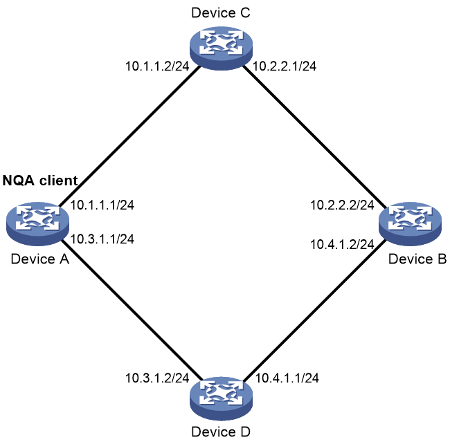
Procedure
# Assign IP addresses to interfaces, as shown in Figure 3. (Details not shown.)
# Configure static routes or a routing protocol to make sure the devices can reach each other. (Details not shown.)
# Create an ICMP echo operation.
<DeviceA> system-view
[DeviceA] nqa entry admin test1
[DeviceA-nqa-admin-test1] type icmp-echo
# Specify 10.2.2.2 as the destination IP address of ICMP echo requests.
[DeviceA-nqa-admin-test1-icmp-echo] destination ip 10.2.2.2
# Specify 10.1.1.2 as the next hop. The ICMP echo requests are sent through Device C to Device B.
[DeviceA-nqa-admin-test1-icmp-echo] next-hop ip 10.1.1.2
# Configure the ICMP echo operation to perform 10 probes.
[DeviceA-nqa-admin-test1-icmp-echo] probe count 10
# Set the probe timeout time to 500 milliseconds for the ICMP echo operation.
[DeviceA-nqa-admin-test1-icmp-echo] probe timeout 500
# Configure the ICMP echo operation to repeat every 5000 milliseconds.
[DeviceA-nqa-admin-test1-icmp-echo] frequency 5000
# Enable saving history records.
[DeviceA-nqa-admin-test1-icmp-echo] history-record enable
# Set the maximum number of history records to 10.
[DeviceA-nqa-admin-test1-icmp-echo] history-record number 10
[DeviceA-nqa-admin-test1-icmp-echo] quit
# Start the ICMP echo operation.
[DeviceA] nqa schedule admin test1 start-time now lifetime forever
# After the ICMP echo operation runs for a period of time, stop the operation.
[DeviceA] undo nqa schedule admin test1
Verifying the configuration
# Display the most recent result of the ICMP echo operation.
[DeviceA] display nqa result admin test1
NQA entry (admin admin, tag test1) test results:
Send operation times: 10 Receive response times: 10
Min/Max/Average round trip time: 2/5/3
Square-Sum of round trip time: 96
Last succeeded probe time: 2011-08-23 15:00:01.2
Extended results:
Packet loss ratio: 0%
Failures due to timeout: 0
Failures due to internal error: 0
Failures due to other errors: 0
# Display the history records of the ICMP echo operation.
[DeviceA] display nqa history admin test1
NQA entry (admin admin, tag test) history records:
Index Response Status Time
370 3 Succeeded 2007-08-23 15:00:01.2
369 3 Succeeded 2007-08-23 15:00:01.2
368 3 Succeeded 2007-08-23 15:00:01.2
367 5 Succeeded 2007-08-23 15:00:01.2
366 3 Succeeded 2007-08-23 15:00:01.2
365 3 Succeeded 2007-08-23 15:00:01.2
364 3 Succeeded 2007-08-23 15:00:01.1
363 2 Succeeded 2007-08-23 15:00:01.1
362 3 Succeeded 2007-08-23 15:00:01.1
361 2 Succeeded 2007-08-23 15:00:01.1
The output shows that the packets sent by Device A can reach Device B through Device C. No packet loss occurs during the operation. The minimum, maximum, and average round-trip times are 2, 5, and 3 milliseconds, respectively.
Example: Configuring the ICMP jitter operation
Network configuration
As shown in Figure 4, configure an ICMP jitter operation to test the jitter between Device A and Device B.

Procedure
1. Assign IP addresses to interfaces, as shown in Figure 4. (Details not shown.)
2. Configure static routes or a routing protocol to make sure the devices can reach each other. (Details not shown.)
3. Configure Device A:
# Create an ICMP jitter operation.
<DeviceA> system-view
[DeviceA] nqa entry admin test1
[DeviceA-nqa-admin-test1] type icmp-jitter
# Specify 10.2.2.2 as the destination address for the operation.
[DeviceA-nqa-admin-test1-icmp-jitter] destination ip 10.2.2.2
# Configure the operation to repeat every 1000 milliseconds.
[DeviceA-nqa-admin-test1-icmp-jitter] frequency 1000
[DeviceA-nqa-admin-test1-icmp-jitter] quit
# Start the ICMP jitter operation.
[DeviceA] nqa schedule admin test1 start-time now lifetime forever
# After the ICMP jitter operation runs for a period of time, stop the operation.
[DeviceA] undo nqa schedule admin test1
Verifying the configuration
# Display the most recent result of the ICMP jitter operation.
[DeviceA] display nqa result admin test1
NQA entry (admin admin, tag test1) test results:
Send operation times: 10 Receive response times: 10
Min/Max/Average round trip time: 1/2/1
Square-Sum of round trip time: 13
Last packet received time: 2015-03-09 17:40:29.8
Extended results:
Packet loss ratio: 0%
Failures due to timeout: 0
Failures due to internal error: 0
Failures due to other errors: 0
Packets out of sequence: 0
Packets arrived late: 0
ICMP-jitter results:
RTT number: 10
Min positive SD: 0 Min positive DS: 0
Max positive SD: 0 Max positive DS: 0
Positive SD number: 0 Positive DS number: 0
Positive SD sum: 0 Positive DS sum: 0
Positive SD average: 0 Positive DS average: 0
Positive SD square-sum: 0 Positive DS square-sum: 0
Min negative SD: 1 Min negative DS: 2
Max negative SD: 1 Max negative DS: 2
Negative SD number: 1 Negative DS number: 1
Negative SD sum: 1 Negative DS sum: 2
Negative SD average: 1 Negative DS average: 2
Negative SD square-sum: 1 Negative DS square-sum: 4
SD average: 1 DS average: 2
One way results:
Max SD delay: 1 Max DS delay: 2
Min SD delay: 1 Min DS delay: 2
Number of SD delay: 1 Number of DS delay: 1
Sum of SD delay: 1 Sum of DS delay: 2
Square-Sum of SD delay: 1 Square-Sum of DS delay: 4
Lost packets for unknown reason: 0
# Display the statistics of the ICMP jitter operation.
[DeviceA] display nqa statistics admin test1
NQA entry (admin admin, tag test1) test statistics:
NO. : 1
Start time: 2015-03-09 17:42:10.7
Life time: 156 seconds
Send operation times: 1560 Receive response times: 1560
Min/Max/Average round trip time: 1/2/1
Square-Sum of round trip time: 1563
Extended results:
Packet loss ratio: 0%
Failures due to timeout: 0
Failures due to internal error: 0
Failures due to other errors: 0
Packets out of sequence: 0
Packets arrived late: 0
ICMP-jitter results:
RTT number: 1560
Min positive SD: 1 Min positive DS: 1
Max positive SD: 1 Max positive DS: 2
Positive SD number: 18 Positive DS number: 46
Positive SD sum: 18 Positive DS sum: 49
Positive SD average: 1 Positive DS average: 1
Positive SD square-sum: 18 Positive DS square-sum: 55
Min negative SD: 1 Min negative DS: 1
Max negative SD: 1 Max negative DS: 2
Negative SD number: 24 Negative DS number: 57
Negative SD sum: 24 Negative DS sum: 58
Negative SD average: 1 Negative DS average: 1
Negative SD square-sum: 24 Negative DS square-sum: 60
SD average: 1 DS average: 1
One way results:
Max SD delay: 1 Max DS delay: 2
Min SD delay: 1 Min DS delay: 1
Number of SD delay: 4 Number of DS delay: 4
Sum of SD delay: 4 Sum of DS delay: 5
Square-Sum of SD delay: 4 Square-Sum of DS delay: 7
Lost packets for unknown reason: 0
Example: Configuring the DHCP operation
Network configuration
As shown in Figure 5, configure a DHCP operation to test the time required for Router A to obtain an IP address from the DHCP server.
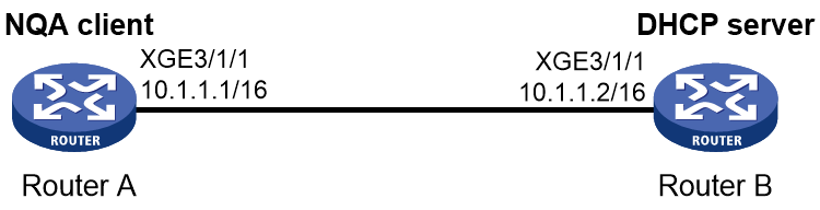
Procedure
# Create a DHCP operation.
<RouterA> system-view
[RouterA] nqa entry admin test1
[RouterA-nqa-admin-test1] type dhcp
# Specify the DHCP server IP address (10.1.1.2) as the destination address.
[RouterA-nqa-admin-test1-dhcp] destination ip 10.1.1.2
# Enable the saving of history records.
[RouterA-nqa-admin-test1-dhcp] history-record enable
[RouterA-nqa-admin-test1-dhcp] quit
# Start the DHCP operation.
[RouterA] nqa schedule admin test1 start-time now lifetime forever
# After the DHCP operation runs for a period of time, stop the operation.
[RouterA] undo nqa schedule admin test1
Verifying the configuration
# Display the most recent result of the DHCP operation.
[RouterA] display nqa result admin test1
NQA entry (admin admin, tag test) test results:
Send operation times: 1 Receive response times: 1
Min/Max/Average round trip time: 512/512/512
Square-Sum of round trip time: 262144
Last succeeded probe time: 2007-11-22 09:54:03.8
Extended results:
Packet loss ratio: 0%
Failures due to timeout: 0
Failures due to internal error: 0
Failures due to other errors: 0
# Display the history records of the DHCP operation.
[RouterA] display nqa history admin test1
NQA entry (admin admin, tag test) history records:
Index Response Status Time
1 512 Succeeded 2007-11-22 09:54:03.8
The output shows that it took Router A 512 milliseconds to obtain an IP address from the DHCP server.
Example: Configuring the DNS operation
Network configuration
As shown in Figure 6, configure a DNS operation to test whether Device A can perform address resolution through the DNS server and test the resolution time.

Procedure
# Assign IP addresses to interfaces, as shown in Figure 6. (Details not shown.)
# Configure static routes or a routing protocol to make sure the devices can reach each other. (Details not shown.)
# Create a DNS operation.
<DeviceA> system-view
[DeviceA] nqa entry admin test1
[DeviceA-nqa-admin-test1] type dns
# Specify the IP address of the DNS server (10.2.2.2) as the destination address.
[DeviceA-nqa-admin-test1-dns] destination ip 10.2.2.2
# Specify host.com as the domain name to be translated.
[DeviceA-nqa-admin-test1-dns] resolve-target host.com
# Enable the saving of history records.
[DeviceA-nqa-admin-test1-dns] history-record enable
[DeviceA-nqa-admin-test1-dns] quit
# Start the DNS operation.
[DeviceA] nqa schedule admin test1 start-time now lifetime forever
# After the DNS operation runs for a period of time, stop the operation.
[DeviceA] undo nqa schedule admin test1
Verifying the configuration
# Display the most recent result of the DNS operation.
[DeviceA] display nqa result admin test1
NQA entry (admin admin, tag test1) test results:
Send operation times: 1 Receive response times: 1
Min/Max/Average round trip time: 62/62/62
Square-Sum of round trip time: 3844
Last succeeded probe time: 2011-11-10 10:49:37.3
Extended results:
Packet loss ratio: 0%
Failures due to timeout: 0
Failures due to internal error: 0
Failures due to other errors: 0
# Display the history records of the DNS operation.
[DeviceA] display nqa history admin test1
NQA entry (admin admin, tag test) history records:
Index Response Status Time
1 62 Succeeded 2011-11-10 10:49:37.3
The output shows that it took Device A 62 milliseconds to translate domain name host.com into an IP address.
Example: Configuring the FTP operation
Network configuration
As shown in Figure 7, configure an FTP operation to test the time required for Device A to upload a file to the FTP server. The login username and password are admin and systemtest, respectively. The file to be transferred to the FTP server is config.txt.

Procedure
# Assign IP addresses to interfaces, as shown in Figure 7. (Details not shown.)
# Configure static routes or a routing protocol to make sure the devices can reach each other. (Details not shown.)
# Create an FTP operation.
<DeviceA> system-view
[DeviceA] nqa entry admin test1
[DeviceA-nqa-admin-test1] type ftp
# Specify the URL of the FTP server.
[DeviceA-nqa-admin-test1-ftp] url ftp://10.2.2.2
# Specify 10.1.1.1 as the source IP address.
[DeviceA-nqa-admin-test1-ftp] source ip 10.1.1.1
# Configure the device to upload file config.txt to the FTP server.
[DeviceA-nqa-admin-test1-ftp] operation put
[DeviceA-nqa-admin-test1-ftp] filename config.txt
# Set the username to admin for the FTP operation.
[DeviceA-nqa-admin-test1-ftp] username admin
# Set the password to systemtest for the FTP operation.
[DeviceA-nqa-admin-test1-ftp] password simple systemtest
# Enable the saving of history records.
[DeviceA-nqa-admin-test1-ftp] history-record enable
[DeviceA-nqa-admin-test1-ftp] quit
# Start the FTP operation.
[DeviceA] nqa schedule admin test1 start-time now lifetime forever
# After the FTP operation runs for a period of time, stop the operation.
[DeviceA] undo nqa schedule admin test1
Verifying the configuration
# Display the most recent result of the FTP operation.
[DeviceA] display nqa result admin test1
NQA entry (admin admin, tag test1) test results:
Send operation times: 1 Receive response times: 1
Min/Max/Average round trip time: 173/173/173
Square-Sum of round trip time: 29929
Last succeeded probe time: 2011-11-22 10:07:28.6
Extended results:
Packet loss ratio: 0%
Failures due to timeout: 0
Failures due to disconnect: 0
Failures due to no connection: 0
Failures due to internal error: 0
Failures due to other errors: 0
# Display the history records of the FTP operation.
[DeviceA] display nqa history admin test1
NQA entry (admin admin, tag test1) history records:
Index Response Status Time
1 173 Succeeded 2011-11-22 10:07:28.6
The output shows that it took Device A 173 milliseconds to upload a file to the FTP server.
Example: Configuring the HTTP operation
Network configuration
As shown in Figure 8, configure an HTTP operation on the NQA client to test the time required to obtain data from the HTTP server.

Procedure
# Assign IP addresses to interfaces, as shown in Figure 8. (Details not shown.)
# Configure static routes or a routing protocol to make sure the devices can reach each other. (Details not shown.)
# Create an HTTP operation.
<DeviceA> system-view
[DeviceA] nqa entry admin test1
[DeviceA-nqa-admin-test1] type http
# Specify the URL of the HTTP server.
[DeviceA-nqa-admin-test1-http] url http://10.2.2.2/index.html
# Configure the HTTP operation to get data from the HTTP server.
[DeviceA-nqa-admin-test1-http] operation get
# Configure the operation to use HTTP version 1.0.
[DeviceA-nqa-admin-test1-http] version v1.0
# Enable the saving of history records.
[DeviceA-nqa-admin-test1-http] history-record enable
[DeviceA-nqa-admin-test1-http] quit
# Start the HTTP operation.
[DeviceA] nqa schedule admin test1 start-time now lifetime forever
# After the HTTP operation runs for a period of time, stop the operation.
[DeviceA] undo nqa schedule admin test1
Verifying the configuration
# Display the most recent result of the HTTP operation.
[DeviceA] display nqa result admin test1
NQA entry (admin admin, tag test1) test results:
Send operation times: 1 Receive response times: 1
Min/Max/Average round trip time: 64/64/64
Square-Sum of round trip time: 4096
Last succeeded probe time: 2011-11-22 10:12:47.9
Extended results:
Packet loss ratio: 0%
Failures due to timeout: 0
Failures due to disconnect: 0
Failures due to no connection: 0
Failures due to internal error: 0
Failures due to other errors: 0
# Display the history records of the HTTP operation.
[DeviceA] display nqa history admin test1
NQA entry (admin admin, tag test1) history records:
Index Response Status Time
1 64 Succeeded 2011-11-22 10:12:47.9
The output shows that it took Device A 64 milliseconds to obtain data from the HTTP server.
Example: Configuring the UDP jitter operation
Network configuration
As shown in Figure 9, configure a UDP jitter operation to test the jitter, delay, and round-trip time between Device A and Device B.

Procedure
1. Assign IP addresses to interfaces, as shown in Figure 9. (Details not shown.)
2. Configure static routes or a routing protocol to make sure the devices can reach each other. (Details not shown.)
3. Configure Device B:
# Enable the NQA server.
<DeviceB> system-view
[DeviceB] nqa server enable
# Configure a listening service to listen to UDP port 9000 on IP address 10.2.2.2.
[DeviceB] nqa server udp-echo 10.2.2.2 9000
4. Configure Device A:
# Create a UDP jitter operation.
<DeviceA> system-view
[DeviceA] nqa entry admin test1
[DeviceA-nqa-admin-test1] type udp-jitter
# Specify 10.2.2.2 as the destination address of the operation.
[DeviceA-nqa-admin-test1-udp-jitter] destination ip 10.2.2.2
# Set the destination port number to 9000.
[DeviceA-nqa-admin-test1-udp-jitter] destination port 9000
# Configure the operation to repeat every 1000 milliseconds.
[DeviceA-nqa-admin-test1-udp-jitter] frequency 1000
[DeviceA-nqa-admin-test1-udp-jitter] quit
# Start the UDP jitter operation.
[DeviceA] nqa schedule admin test1 start-time now lifetime forever
# After the UDP jitter operation runs for a period of time, stop the operation.
[DeviceA] undo nqa schedule admin test1
Verifying the configuration
# Display the most recent result of the UDP jitter operation.
[DeviceA] display nqa result admin test1
NQA entry (admin admin, tag test1) test results:
Send operation times: 10 Receive response times: 10
Min/Max/Average round trip time: 15/32/17
Square-Sum of round trip time: 3235
Last packet received time: 2011-05-29 13:56:17.6
Extended results:
Packet loss ratio: 0%
Failures due to timeout: 0
Failures due to internal error: 0
Failures due to other errors: 0
Packets out of sequence: 0
Packets arrived late: 0
UDP-jitter results:
RTT number: 10
Min positive SD: 4 Min positive DS: 1
Max positive SD: 21 Max positive DS: 28
Positive SD number: 5 Positive DS number: 4
Positive SD sum: 52 Positive DS sum: 38
Positive SD average: 10 Positive DS average: 10
Positive SD square-sum: 754 Positive DS square-sum: 460
Min negative SD: 1 Min negative DS: 6
Max negative SD: 13 Max negative DS: 22
Negative SD number: 4 Negative DS number: 5
Negative SD sum: 38 Negative DS sum: 52
Negative SD average: 10 Negative DS average: 10
Negative SD square-sum: 460 Negative DS square-sum: 754
SD average: 10 DS average: 10
One way results:
Max SD delay: 15 Max DS delay: 16
Min SD delay: 7 Min DS delay: 7
Number of SD delay: 10 Number of DS delay: 10
Sum of SD delay: 78 Sum of DS delay: 85
Square-Sum of SD delay: 666 Square-Sum of DS delay: 787
SD lost packets: 0 DS lost packets: 0
Lost packets for unknown reason: 0
# Display the statistics of the UDP jitter operation.
[DeviceA] display nqa statistics admin test1
NQA entry (admin admin, tag test1) test statistics:
NO. : 1
Start time: 2011-05-29 13:56:14.0
Life time: 47 seconds
Send operation times: 410 Receive response times: 410
Min/Max/Average round trip time: 1/93/19
Square-Sum of round trip time: 206176
Extended results:
Packet loss ratio: 0%
Failures due to timeout: 0
Failures due to internal error: 0
Failures due to other errors: 0
Packets out of sequence: 0
Packets arrived late: 0
UDP-jitter results:
RTT number: 410
Min positive SD: 3 Min positive DS: 1
Max positive SD: 30 Max positive DS: 79
Positive SD number: 186 Positive DS number: 158
Positive SD sum: 2602 Positive DS sum: 1928
Positive SD average: 13 Positive DS average: 12
Positive SD square-sum: 45304 Positive DS square-sum: 31682
Min negative SD: 1 Min negative DS: 1
Max negative SD: 30 Max negative DS: 78
Negative SD number: 181 Negative DS number: 209
Negative SD sum: 181 Negative DS sum: 209
Negative SD average: 13 Negative DS average: 14
Negative SD square-sum: 46994 Negative DS square-sum: 3030
SD average: 10 DS average: 7
One way results:
Max SD delay: 46 Max DS delay: 46
Min SD delay: 7 Min DS delay: 7
Number of SD delay: 410 Number of DS delay: 410
Sum of SD delay: 3705 Sum of DS delay: 3891
Square-Sum of SD delay: 45987 Square-Sum of DS delay: 49393
SD lost packets: 0 DS lost packets: 0
Lost packets for unknown reason: 0
Example: Configuring the SNMP operation
Network configuration
As shown in Figure 10, configure an SNMP operation to test the time the NQA client uses to get a response from the SNMP agent.

Procedure
1. Assign IP addresses to interfaces, as shown in Figure 10. (Details not shown.)
2. Configure static routes or a routing protocol to make sure the devices can reach each other. (Details not shown.)
3. Configure the SNMP agent (Device B):
# Set the SNMP version to all.
<DeviceB> system-view
[DeviceB] snmp-agent sys-info version all
# Set the read community to public.
[DeviceB] snmp-agent community read public
# Set the write community to private.
[DeviceB] snmp-agent community write private
4. Configure Device A:
# Create an SNMP operation.
<DeviceA> system-view
[DeviceA] nqa entry admin test1
[DeviceA-nqa-admin-test1] type snmp
# Specify 10.2.2.2 as the destination IP address of the SNMP operation.
[DeviceA-nqa-admin-test1-snmp] destination ip 10.2.2.2
# Enable the saving of history records.
[DeviceA-nqa-admin-test1-snmp] history-record enable
[DeviceA-nqa-admin-test1-snmp] quit
# Start the SNMP operation.
[DeviceA] nqa schedule admin test1 start-time now lifetime forever
# After the SNMP operation runs for a period of time, stop the operation.
[DeviceA] undo nqa schedule admin test1
Verifying the configuration
# Display the most recent result of the SNMP operation.
[DeviceA] display nqa result admin test1
NQA entry (admin admin, tag test1) test results:
Send operation times: 1 Receive response times: 1
Min/Max/Average round trip time: 50/50/50
Square-Sum of round trip time: 2500
Last succeeded probe time: 2011-11-22 10:24:41.1
Extended results:
Packet loss ratio: 0%
Failures due to timeout: 0
Failures due to internal error: 0
Failures due to other errors: 0
# Display the history records of the SNMP operation.
[DeviceA] display nqa history admin test1
NQA entry (admin admin, tag test1) history records:
Index Response Status Time
1 50 Succeeded 2011-11-22 10:24:41.1
The output shows that it took Device A 50 milliseconds to receive a response from the SNMP agent.
Example: Configuring the TCP operation
Network configuration
As shown in Figure 11, configure a TCP operation to test the time required for Device A to establish a TCP connection with Device B.

Procedure
1. Assign IP addresses to interfaces, as shown in Figure 11. (Details not shown.)
2. Configure static routes or a routing protocol to make sure the devices can reach each other. (Details not shown.)
3. Configure Device B:
# Enable the NQA server.
<DeviceB> system-view
[DeviceB] nqa server enable
# Configure a listening service to listen to TCP port 9000 on IP address 10.2.2.2.
[DeviceB] nqa server tcp-connect 10.2.2.2 9000
4. Configure Device A:
# Create a TCP operation.
<DeviceA> system-view
[DeviceA] nqa entry admin test1
[DeviceA-nqa-admin-test1] type tcp
# Specify 10.2.2.2 as the destination IP address.
[DeviceA-nqa-admin-test1-tcp] destination ip 10.2.2.2
# Set the destination port number to 9000.
[DeviceA-nqa-admin-test1-tcp] destination port 9000
# Enable the saving of history records.
[DeviceA-nqa-admin-test1-tcp] history-record enable
[DeviceA-nqa-admin-test1-tcp] quit
# Start the TCP operation.
[DeviceA] nqa schedule admin test1 start-time now lifetime forever
# After the TCP operation runs for a period of time, stop the operation.
[DeviceA] undo nqa schedule admin test1
Verifying the configuration
# Display the most recent result of the TCP operation.
[DeviceA] display nqa result admin test1
NQA entry (admin admin, tag test1) test results:
Send operation times: 1 Receive response times: 1
Min/Max/Average round trip time: 13/13/13
Square-Sum of round trip time: 169
Last succeeded probe time: 2011-11-22 10:27:25.1
Extended results:
Packet loss ratio: 0%
Failures due to timeout: 0
Failures due to disconnect: 0
Failures due to no connection: 0
Failures due to internal error: 0
Failures due to other errors: 0
# Display the history records of the TCP operation.
[DeviceA] display nqa history admin test1
NQA entry (admin admin, tag test1) history records:
Index Response Status Time
1 13 Succeeded 2011-11-22 10:27:25.1
The output shows that it took Device A 13 milliseconds to establish a TCP connection to port 9000 on the NQA server.
Example: Configuring the UDP echo operation
Network configuration
As shown in Figure 12, configure a UDP echo operation on the NQA client to test the round-trip time to Device B. The destination port number is 8000.

Procedure
1. Assign IP addresses to interfaces, as shown in Figure 12. (Details not shown.)
2. Configure static routes or a routing protocol to make sure the devices can reach each other. (Details not shown.)
3. Configure Device B:
# Enable the NQA server.
<DeviceB> system-view
[DeviceB] nqa server enable
# Configure a listening service to listen to UDP port 8000 on IP address 10.2.2.2.
[DeviceB] nqa server udp-echo 10.2.2.2 8000
4. Configure Device A:
# Create a UDP echo operation.
<DeviceA> system-view
[DeviceA] nqa entry admin test1
[DeviceA-nqa-admin-test1] type udp-echo
# Specify 10.2.2.2 as the destination IP address.
[DeviceA-nqa-admin-test1-udp-echo] destination ip 10.2.2.2
# Set the destination port number to 8000.
[DeviceA-nqa-admin-test1-udp-echo] destination port 8000
# Enable the saving of history records.
[DeviceA-nqa-admin-test1-udp-echo] history-record enable
[DeviceA-nqa-admin-test1-udp-echo] quit
# Start the UDP echo operation.
[DeviceA] nqa schedule admin test1 start-time now lifetime forever
# After the UDP echo operation runs for a period of time, stop the operation.
[DeviceA] undo nqa schedule admin test1
Verifying the configuration
# Display the most recent result of the UDP echo operation.
[DeviceA] display nqa result admin test1
NQA entry (admin admin, tag test1) test results:
Send operation times: 1 Receive response times: 1
Min/Max/Average round trip time: 25/25/25
Square-Sum of round trip time: 625
Last succeeded probe time: 2011-11-22 10:36:17.9
Extended results:
Packet loss ratio: 0%
Failures due to timeout: 0
Failures due to internal error: 0
Failures due to other errors: 0
# Display the history records of the UDP echo operation.
[DeviceA] display nqa history admin test1
NQA entry (admin admin, tag test1) history records:
Index Response Status Time
1 25 Succeeded 2011-11-22 10:36:17.9
The output shows that the round-trip time between Device A and port 8000 on Device B is 25 milliseconds.
Example: Configuring the UDP tracert operation
Network configuration
As shown in Figure 13, configure a UDP tracert operation to determine the routing path from Device A to Device B.

Procedure
1. Assign IP addresses to interfaces, as shown in Figure 13. (Details not shown.)
2. Configure static routes or a routing protocol to make sure the devices can reach each other. (Details not shown.)
3. Execute the ip ttl-expires enable command on the intermediate devices and execute the ip unreachables enable command on Device B.
4. Configure Device A:
# Create a UDP tracert operation.
<DeviceA> system-view
[DeviceA] nqa entry admin test1
[DeviceA-nqa-admin-test1] type udp-tracert
# Specify 10.2.2.2 as the destination IP address.
[DeviceA-nqa-admin-test1-udp-tracert] destination ip 10.2.2.2
# Set the destination port number to 33434.
[DeviceA-nqa-admin-test1-udp-tracert] destination port 33434
# Configure Device A to perform three probes to each hop.
[DeviceA-nqa-admin-test1-udp-tracert] probe count 3
# Set the probe timeout time to 500 milliseconds.
[DeviceA-nqa-admin-test1-udp-tracert] probe timeout 500
# Configure the UDP tracert operation to repeat every 5000 milliseconds.
[DeviceA-nqa-admin-test1-udp-tracert] frequency 5000
# Specify Ten-GigabitEthernet 3/1/1 as the output interface for UDP packets.
[DeviceA-nqa-admin-test1-udp-tracert] out interface ten-gigabitethernet 3/1/1
# Enable the no-fragmentation feature.
[DeviceA-nqa-admin-test1-udp-tracert] no-fragment enable
# Set the maximum number of consecutive probe failures to 6.
[DeviceA-nqa-admin-test1-udp-tracert] max-failure 6
# Set the TTL value to 1 for UDP packets in the start round of the UDP tracert operation.
[DeviceA-nqa-admin-test1-udp-tracert] init-ttl 1
# Start the UDP tracert operation.
[DeviceA] nqa schedule admin test1 start-time now lifetime forever
# After the UDP tracert operation runs for a period of time, stop the operation.
[DeviceA] undo nqa schedule admin test1
Verifying the configuration
# Display the most recent result of the UDP tracert operation.
[DeviceA] display nqa result admin test1
NQA entry (admin admin, tag test1) test results:
Send operation times: 6 Receive response times: 6
Min/Max/Average round trip time: 1/1/1
Square-Sum of round trip time: 1
Last succeeded probe time: 2013-09-09 14:46:06.2
Extended results:
Packet loss in test: 0%
Failures due to timeout: 0
Failures due to internal error: 0
Failures due to other errors: 0
UDP-tracert results:
TTL Hop IP Time
1 3.1.1.1 2013-09-09 14:46:03.2
2 10.2.2.2 2013-09-09 14:46:06.2
# Display the history records of the UDP tracert operation.
[DeviceA] display nqa history admin test1
NQA entry (admin admin, tag test1) history records:
Index TTL Response Hop IP Status Time
1 2 2 10.2.2.2 Succeeded 2013-09-09 14:46:06.2
1 2 1 10.2.2.2 Succeeded 2013-09-09 14:46:05.2
1 2 2 10.2.2.2 Succeeded 2013-09-09 14:46:04.2
1 1 1 3.1.1.1 Succeeded 2013-09-09 14:46:03.2
1 1 2 3.1.1.1 Succeeded 2013-09-09 14:46:02.2
1 1 1 3.1.1.1 Succeeded 2013-09-09 14:46:01.2
Example: Configuring the voice operation
Network configuration
As shown in Figure 14, configure a voice operation to test jitters, delay, MOS, and ICPIF between Device A and Device B.

Procedure
1. Assign IP addresses to interfaces, as shown in Figure 14. (Details not shown.)
2. Configure static routes or a routing protocol to make sure the devices can reach each other. (Details not shown.)
3. Configure Device B:
# Enable the NQA server.
<DeviceB> system-view
[DeviceB] nqa server enable
# Configure a listening service to listen to UDP port 9000 on IP address 10.2.2.2.
[DeviceB] nqa server udp-echo 10.2.2.2 9000
4. Configure Device A:
# Create a voice operation.
<DeviceA> system-view
[DeviceA] nqa entry admin test1
[DeviceA-nqa-admin-test1] type voice
# Specify 10.2.2.2 as the destination IP address.
[DeviceA-nqa-admin-test1-voice] destination ip 10.2.2.2
# Set the destination port number to 9000.
[DeviceA-nqa-admin-test1-voice] destination port 9000
[DeviceA-nqa-admin-test1-voice] quit
# Start the voice operation.
[DeviceA] nqa schedule admin test1 start-time now lifetime forever
# After the voice operation runs for a period of time, stop the operation.
[DeviceA] undo nqa schedule admin test1
Verifying the configuration
# Display the most recent result of the voice operation.
[DeviceA] display nqa result admin test1
NQA entry (admin admin, tag test1) test results:
Send operation times: 1000 Receive response times: 1000
Min/Max/Average round trip time: 31/1328/33
Square-Sum of round trip time: 2844813
Last packet received time: 2011-06-13 09:49:31.1
Extended results:
Packet loss ratio: 0%
Failures due to timeout: 0
Failures due to internal error: 0
Failures due to other errors: 0
Packets out of sequence: 0
Packets arrived late: 0
Voice results:
RTT number: 1000
Min positive SD: 1 Min positive DS: 1
Max positive SD: 204 Max positive DS: 1297
Positive SD number: 257 Positive DS number: 259
Positive SD sum: 759 Positive DS sum: 1797
Positive SD average: 2 Positive DS average: 6
Positive SD square-sum: 54127 Positive DS square-sum: 1691967
Min negative SD: 1 Min negative DS: 1
Max negative SD: 203 Max negative DS: 1297
Negative SD number: 255 Negative DS number: 259
Negative SD sum: 759 Negative DS sum: 1796
Negative SD average: 2 Negative DS average: 6
Negative SD square-sum: 53655 Negative DS square-sum: 1691776
SD average: 2 DS average: 6
One way results:
Max SD delay: 343 Max DS delay: 985
Min SD delay: 343 Min DS delay: 985
Number of SD delay: 1 Number of DS delay: 1
Sum of SD delay: 343 Sum of DS delay: 985
Square-Sum of SD delay: 117649 Square-Sum of DS delay: 970225
SD lost packets: 0 DS lost packets: 0
Lost packets for unknown reason: 0
Voice scores:
MOS value: 4.38 ICPIF value: 0
# Display the statistics of the voice operation.
[DeviceA] display nqa statistics admin test1
NQA entry (admin admin, tag test1) test statistics:
NO. : 1
Start time: 2011-06-13 09:45:37.8
Life time: 331 seconds
Send operation times: 4000 Receive response times: 4000
Min/Max/Average round trip time: 15/1328/32
Square-Sum of round trip time: 7160528
Extended results:
Packet loss ratio: 0%
Failures due to timeout: 0
Failures due to internal error: 0
Failures due to other errors: 0
Packets out of sequence: 0
Packets arrived late: 0
Voice results:
RTT number: 4000
Min positive SD: 1 Min positive DS: 1
Max positive SD: 360 Max positive DS: 1297
Positive SD number: 1030 Positive DS number: 1024
Positive SD sum: 4363 Positive DS sum: 5423
Positive SD average: 4 Positive DS average: 5
Positive SD square-sum: 497725 Positive DS square-sum: 2254957
Min negative SD: 1 Min negative DS: 1
Max negative SD: 360 Max negative DS: 1297
Negative SD number: 1028 Negative DS number: 1022
Negative SD sum: 1028 Negative DS sum: 1022
Negative SD average: 4 Negative DS average: 5
Negative SD square-sum: 495901 Negative DS square-sum: 5419
SD average: 2 DS average: 3
One way results:
Max SD delay: 359 Max DS delay: 985
Min SD delay: 0 Min DS delay: 0
Number of SD delay: 4 Number of DS delay: 4
Sum of SD delay: 1390 Sum of DS delay: 1079
Square-Sum of SD delay: 483202 Square-Sum of DS delay: 973651
SD lost packets: 0 DS lost packets: 0
Lost packets for unknown reason: 0
Voice scores:
Max MOS value: 4.38 Min MOS value: 4.38
Max ICPIF value: 0 Min ICPIF value: 0
Example: Configuring the DLSw operation
Network configuration
As shown in Figure 15, configure a DLSw operation to test the response time of the DLSw device.

Procedure
# Assign IP addresses to interfaces, as shown in Figure 15. (Details not shown.)
# Configure static routes or a routing protocol to make sure the devices can reach each other. (Details not shown.)
# Create a DLSw operation.
<DeviceA> system-view
[DeviceA] nqa entry admin test1
[DeviceA-nqa-admin-test1] type dlsw
# Specify 10.2.2.2 as the destination IP address.
[DeviceA-nqa-admin-test1-dlsw] destination ip 10.2.2.2
# Enable the saving of history records.
[DeviceA-nqa-admin-test1-dlsw] history-record enable
[DeviceA-nqa-admin-test1-dlsw] quit
# Start the DLSw operation.
[DeviceA] nqa schedule admin test1 start-time now lifetime forever
# After the DLSw operation runs for a period of time, stop the operation.
[DeviceA] undo nqa schedule admin test1
Verifying the configuration
# Display the most recent result of the DLSw operation.
[DeviceA] display nqa result admin test1
NQA entry (admin admin, tag test1) test results:
Send operation times: 1 Receive response times: 1
Min/Max/Average round trip time: 19/19/19
Square-Sum of round trip time: 361
Last succeeded probe time: 2011-11-22 10:40:27.7
Extended results:
Packet loss ratio: 0%
Failures due to timeout: 0
Failures due to disconnect: 0
Failures due to no connection: 0
Failures due to internal error: 0
Failures due to other errors: 0
# Display the history records of the DLSw operation.
[DeviceA] display nqa history admin test1
NQA entry (admin admin, tag test1) history records:
Index Response Status Time
1 19 Succeeded 2011-11-22 10:40:27.7
The output shows that the response time of the DLSw device is 19 milliseconds.
Example: Configuring the path jitter operation
Network configuration
As shown in Figure 16, configure a path jitter operation to test the round trip time and jitters from Device A to Device B and Device C.

Procedure
# Assign IP addresses to interfaces, as shown in Figure 16. (Details not shown.)
# Configure static routes or a routing protocol to make sure the devices can reach each other. (Details not shown.)
# Execute the ip ttl-expires enable command on Device B and execute the ip unreachables enable command on Device C.
# Create a path jitter operation.
<DeviceA> system-view
[DeviceA] nqa entry admin test1
[DeviceA-nqa-admin-test1] type path-jitter
# Specify 10.2.2.2 as the destination IP address of ICMP echo requests.
[DeviceA-nqa-admin-test1-path-jitter] destination ip 10.2.2.2
# Configure the path jitter operation to repeat every 10000 milliseconds.
[DeviceA-nqa-admin-test1-path-jitter] frequency 10000
[DeviceA-nqa-admin-test1-path-jitter] quit
# Start the path jitter operation.
[DeviceA] nqa schedule admin test1 start-time now lifetime forever
# After the path jitter operation runs for a period of time, stop the operation.
[DeviceA] undo nqa schedule admin test1
Verifying the configuration
# Display the most recent result of the path jitter operation.
[DeviceA] display nqa result admin test1
NQA entry (admin admin, tag test1) test results:
Hop IP 10.1.1.2
Basic Results
Send operation times: 10 Receive response times: 10
Min/Max/Average round trip time: 9/21/14
Square-Sum of round trip time: 2419
Extended Results
Failures due to timeout: 0
Failures due to internal error: 0
Failures due to other errors: 0
Packets out of sequence: 0
Packets arrived late: 0
Path-Jitter Results
Jitter number: 9
Min/Max/Average jitter: 1/10/4
Positive jitter number: 6
Min/Max/Average positive jitter: 1/9/4
Sum/Square-Sum positive jitter: 25/173
Negative jitter number: 3
Min/Max/Average negative jitter: 2/10/6
Sum/Square-Sum positive jitter: 19/153
Hop IP 10.2.2.2
Basic Results
Send operation times: 10 Receive response times: 10
Min/Max/Average round trip time: 15/40/28
Square-Sum of round trip time: 4493
Extended Results
Failures due to timeout: 0
Failures due to internal error: 0
Failures due to other errors: 0
Packets out of sequence: 0
Packets arrived late: 0
Path-Jitter Results
Jitter number: 9
Min/Max/Average jitter: 1/10/4
Positive jitter number: 6
Min/Max/Average positive jitter: 1/9/4
Sum/Square-Sum positive jitter: 25/173
Negative jitter number: 3
Min/Max/Average negative jitter: 2/10/6
Sum/Square-Sum positive jitter: 19/153
Example: Configuring the path quality analysis operation
This example uses the throughput operation. You can configure the frame loss or latency operation in the same way the throughput operation is configured.
Network configuration
As shown in Figure 17, configure a throughput operation to test the throughput of the network path from Device A to Device B over an MPLS L2VPN network.
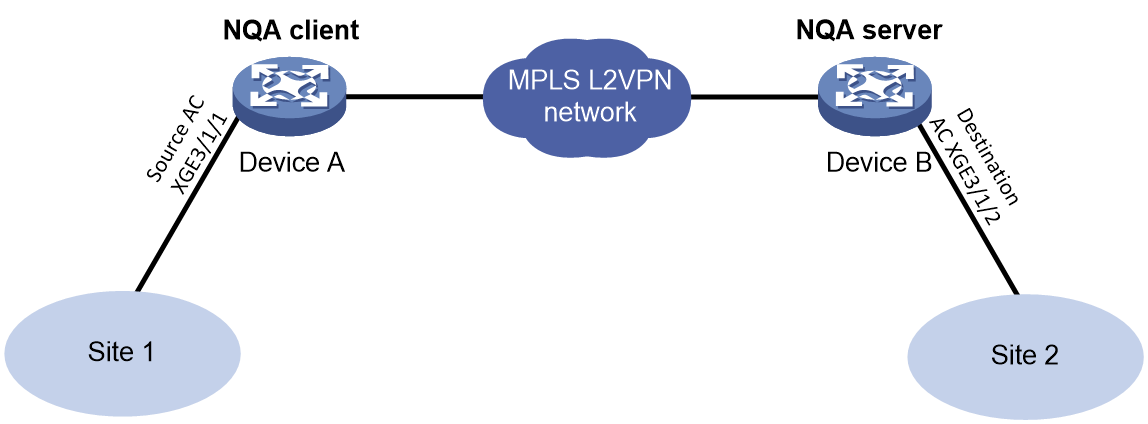
Procedure
1. Set up and configure the MPLS L2VPN network. (Details not shown.)
2. Configure Device B:
# Configure a reflector on the NQA server for the path quality analysis operations.
[DeviceB] nqa reflector 1 interface ten-gigabitethernet 3/1/2 service-instance 1 destination-mac 2-2-2 source-mac 1-1-1
# Enable the NQA server.
[DeviceB] nqa server enable
3. Configure Device A:
# Create a throughput operation.
<DeviceA> system-view
[DeviceA] nqa entry admin test1
[DeviceA-nqa-admin-test1] type throughput
# Specify 1-1-1 as the source MAC address for the probe packets.
[DeviceA-nqa-admin-test1-throughput] source mac 1-1-1
# Specify 2-2-2 as the destination MAC address for the probe packets.
[DeviceA-nqa-admin-test1-path-jitter] destination mac 2-2-2
# Specify the AC interface to be used as the source interface for the probe packets. This example uses the AC interface in Ethernet service instance 1 on GigabitEthernet 1/0/1.
[DeviceA-nqa-admin-test1-throughput] source interface ten-gigabitethernet 3/1/1 service-instance 1
# Specify a packet size list of 64 bytes, 512 bytes, 1024 bytes, and 1280 bytes.
[DeviceA-nqa-admin-test1-throughput] frame-size 64 512 1024 1280
# Start the path quality analysis operation. The reflector will automatically stop the operation after it is completed.
[DeviceA-nqa-admin-test1-throughput] start
[DeviceA-nqa-admin-test1-throughput] quit
Verifying the configuration
# Display the result of the throughput operation.
[DeviceA] display nqa result
NQA entry (admin admin, tag test1) test results:
Basic results :
Initial speed(Kbps) : 100000
Speed granularity(Kbps): 1000
Probe duration(s) : 60
Probe interval(s) : 4
Allowed-loss-ratio : 1/10000
Throughput results:
Frame size(Byte): 64
Current speed(Kbps): -
Frame-loss(Loss/Tx): -
Status : Failed
Time : 2015-03-17 07:20:40.8
Frame size(Byte): 512
Current speed(Kbps): 4000
Frame-loss(Loss/Tx): 0/10000
Status : Succeeded
Time : 2015-03-17 07:21:40.8
Frame size(Byte): 1024
Current speed(Kbps): 8000
Frame-loss(Loss/Tx): 0/10000
Status : Succeeded
Time : 2015-03-17 07:22:52.8
Frame size(Byte): 1280
Current speed(Kbps): 10000
Frame-loss(Loss/Tx): 0/10000
Status : Succeeded
Time : 2015-03-17 07:23:45.8
Frame size(Byte): 1518
Current speed(Kbps): 10000
Frame-loss(Loss/Tx): 0/10000
Status : Succeeded
Time : 2015-03-17 07:24:45.8
Example: Configuring Y.1564 operation on a Layer 2 Ethernet network
Network configuration
As shown in Figure 18, configure a Y.1564 operation to test the service quality from Device A to Device B over a Layer 2 Ethernet network.

Procedure
1. Configure Device B:
# Configure an NQA reflector on the NQA server for the Y.1564 operation.
<DeviceB> system-view
[DeviceB] nqa reflector 1 interface ten-gigabitethernet 3/1/2 destination-port 20000 source-port 10000 destination-mac 2-2-2 source-mac 1-1-1 vlan 100
# Enable the NQA server.
[DeviceB] nqa server enable
2. Configure Device A:
# Create a Y.1564 operation.
<DeviceA> system-view
[DeviceA] nqa entry admin test1
[DeviceA-nqa-admin-test1] type y1564
# Specify 10000 as the source port number for the probe packets.
[DeviceA-nqa-admin-test1-y1564] source port 10000
# Specify 20000 as the destination port number for the probe packets.
[DeviceA-nqa-admin-test1-y1564] destination port 20000
# Specify 1-1-1 as the source MAC address for the probe packets.
[DeviceA-nqa-admin-test1-y1564] source mac 1-1-1
# Specify 2-2-2 as the source MAC address for the probe packets.
[DeviceA-nqa-admin-test1-y1564] destination mac 2-2-2
# Specify GigabitEthernet 1/0/1 as the source interface for the probe packets.
[DeviceA-nqa-admin-test1-y1564] source interface ten-gigabitethernet 3/1/1
# Specify 1000 and 600 as the CIR and PIR, respectively.
[DeviceA-nqa-admin-test1-y1564] bandwidth cir 1000 pir 600
# Specify 1000 as the FDV threshold.
[DeviceA-nqa-admin-test1-y1564] allowed-jitter 1000
# Specify 1000 as the FLR threshold.
[DeviceA-nqa-admin-test1-y1564] allowed-frame-loss 1000
# Specify 1000 as the FTD threshold.
[DeviceA-nqa-admin-test1-y1564] allowed-transfer-delay 1000
# Enable the traffic policing test.
[DeviceA-nqa-admin-test1-y1564] traffic-policing-test enable
# Specify VLAN 100 as the VLAN ID for the Y.1564 operation.
[DeviceA-nqa-admin-test1-y1564] vlan 100
# Start the Y.1564 operation.
[DeviceA-nqa-admin-test1-throughput] start
[DeviceA-nqa-admin-test1-y1564] quit
The operation duration relates to the configured test items and the item duration.
Verifying the configuration
# Display the result of the Y.1564 operation.
[DeviceA] display nqa result
NQA entry (admin admin, tag test1) test results:
Status : Succeeded
Last test : Service performance test
Estimated total time (s) : 909
Actual test time used (s) : 909
Detailed test results:
CIR test (with the step of 1):
Start time : 2018-11-03 11:51:38.1
End time : 2018-11-03 11:51:41.3
Status : Succeeded
Min/Max/Average IR (kbps) : 998/1002/1000
Min/Max/Average FTD (us) : 232/236/234
Min/Max/Average FDV (us) : 32/36/34
FL count/FLR : 2/0.002%
Packets out of order : 0
Severely Err Secs/AVAIL : 0/100.000%
PIR test (color-blind):
Start time : 2018-11-03 11:51:41.1
End time : 2018-11-03 11:51:44.3
Status : Succeeded
Min/Max/Average IR (kbps) : 1598/1602/1600
Min/Max/Average FTD (us) : 373/377/375
Min/Max/Average FDV (us) : 73/77/75
FL count/FLR : 2/0.002%
Packets out of order : 0
Severely Err Secs/AVAIL : 0/100.000%
Traffic policing test (color-blind):
Start time : 2018-11-03 11:51:44.3
End time : 2018-11-03 11:51:47.5
Status : Succeeded
Min/Max/Average IR (kbps) : 1310/1314/1312
Min/Max/Average FTD (us) : 409/413/411
Min/Max/Average FDV (us) : 9/13/11
FL count/FLR : 5/0.005%
Packets out of order : 0
Severely Err Secs/AVAIL : 0/100.000%
Service performance test:
Start time : 2018-11-03 11:51:47.5
End time : 2018-11-03 12:06:47.7
Status : Succeeded
Min/Max/Average IR (kbps) : 998/1002/1000
Min/Max/Average FTD (us) : 232/236/234
Min/Max/Average FDV (us) : 32/36/34
FL count/FLR : 2/0.002%
Packets out of order : 0
Severely Err Secs/AVAIL : 0/100.000%
Example: Configuring Y.1564 operation on a Layer 3 Ethernet network
Network configuration
As shown in Figure 19, configure a Y.1564 operation to test the service quality from Device A to Device B over a Layer 3 Ethernet network.

Procedure
1. Assign IP addresses to interfaces, as shown in Figure 19. (Details not shown.)
2. Configure static routes or a routing protocol to make sure the devices can reach each other. (Details not shown.)
3. Configure Device B:
# Configure an NQA reflector on the NQA server for the Y.1564 operation.
<DeviceB> system-view
[DeviceB] nqa reflector 1 interface ten-gigabitethernet 3/1/2 ip destination 10.2.2.2 source 10.1.1.1 destination-port 20000 source-port 10000
# Enable the NQA server.
[DeviceB] nqa server enable
4. Configure Device A:
# Create a Y.1564 operation.
<DeviceA> system-view
[DeviceA] nqa entry admin test1
[DeviceA-nqa-admin-test1] type y1564
# Specify 10.1.1.1 as the source IP address for the probe packets.
[DeviceA-nqa-admin-test1-y1564] source ip 10.1.1.1
# Specify 10.2.2.2 as the destination IP address for the probe packets.
[DeviceA-nqa-admin-test1-y1564] destination ip 10.2.2.2
# Specify 10000 as the source port number for the probe packets.
[DeviceA-nqa-admin-test1-y1564] source port 10000
# Specify 20000 as the destination port number for the probe packets.
[DeviceA-nqa-admin-test1-y1564] destination port 20000
# Specify GigabitEthernet 1/0/1 as the source interface for the probe packets.
[DeviceA-nqa-admin-test1-y1564] source interface ten-gigabitethernet 3/1/1
# Configure the Y.1564 operation basic parameters.
[DeviceA-nqa-admin-test1-y1564] bandwidth cir 10000 pir 1000
[DeviceA-nqa-admin-test1-y1564] allowed-jitter 1000
[DeviceA-nqa-admin-test1-y1564] allowed-frame-loss 20
[DeviceA-nqa-admin-test1-y1564] allowed-transfer-delay 10000
# Enable the traffic policing test.
[DeviceA-nqa-admin-test1-y1564] traffic-policing-test enable
# Start the Y.1564 operation.
[DeviceA-nqa-admin-test1-y1564] start
[DeviceA-nqa-admin-test1-y1564] quit
The operation duration relates to the configured test items and the item duration.
Verifying the configuration
# Display the result of the Y.1564 operation.
[DeviceA] display nqa result
NQA entry (admin admin, tag test1) test results:
Status : In progress
Last test : Traffic policing test
Estimated total time (s) : 909
Actual test time used (s) : 24
Detailed test results:
CIR test (with the step of 1):
Start time : 2018-11-03 13:39:10.3
End time : 2018-11-03 13:39:13.5
Status : Succeeded
Min/Max/Average IR (kbps) : 9998/10002/10000
Min/Max/Average FTD (us) : 347/351/349
Min/Max/Average FDV (us) : 47/51/49
FL count/FLR : 2/0.002%
Packets out of order : 0
Severely Err Secs/AVAIL : 0/100.000%
PIR test (color-blind):
Start time : 2018-11-03 13:39:13.5
End time : 2018-11-03 13:39:16.7
Status : Succeeded
Min/Max/Average IR (kbps) : 10998/11002/11000
Min/Max/Average FTD (us) : 582/586/584
Min/Max/Average FDV (us) : 82/86/84
FL count/FLR : 2/0.002%0
Packets out of order : 0
Severely Err Secs/AVAIL : 0/100.000%
Traffic policing test (color-blind):
Start time : 2018-11-03 13:39:16.7
End time : 2018-11-03 13:39:19.9
Status : Succeeded
Min/Max/Average IR (kbps) : 10123/10127/10125
Min/Max/Average FTD (us) : 169/173/171
Min/Max/Average FDV (us) : 69/73/71
FL count/FLR : 6/0.006%
Packets out of order : 0
Severely Err Secs/AVAIL : 0/100.000%
Example: Configuring Y.1564 operation on a Layer 3 Ethernet gateway
Network configuration
As shown in Figure 20, configure a Y.1564 operation to test the service quality from Router A to Switch A over a Layer 3 Ethernet network.

Procedure
1. Assign IP addresses to interfaces, as shown in Figure 20. (Details not shown.)
2. Configure static routes or a routing protocol to make sure the devices can reach each other. (Details not shown.)
3. Configure Switch A:
# Configure an NQA reflector on the NQA server for the Y.1564 operation.
<SwitchA> system-view
[SwitchA] nqa reflector 1 interface ten-gigabitethernet 3/1/1 ip destination 10.2.2.2 source 10.1.1.1 destination-port 20000 source-port 10000
# Enable the NQA server.
[SwitchA] nqa server enable
4. Configure Router A:
# Create a Y.1564 operation.
<RouterA> system-view
[RouterA] nqa entry admin test1
[RouterA-nqa-admin-test1] type y1564
# Specify the gateway IP address (10.1.1.1) as the source IP address for the probe packets.
[RouterA-nqa-admin-test1-y1564] source ip 10.1.1.1
# Specify 10.2.2.2 as the destination IP address for the probe packets.
[RouterA-nqa-admin-test1-y1564] destination ip 10.2.2.2
# Specify 10000 as the source port number for the probe packets.
[RouterA-nqa-admin-test1-y1564] source port 10000
# Specify 20000 as the destination port number for the probe packets.
[RouterA-nqa-admin-test1-y1564] destination port 20000
# Specify GigabitEthernet 1/0/1 as the source interface for the probe packets.
[RouterA-nqa-admin-test1-y1564] out interface ten-gigabitethernet 3/1/1
# Configure the Y.1564 operation basic parameters.
[RouterA-nqa-admin-test1-y1564] bandwidth cir 100 pir 10000
[RouterA-nqa-admin-test1-y1564] allowed-jitter 1000
[RouterA-nqa-admin-test1-y1564] allowed-frame-loss 1000
[RouterA-nqa-admin-test1-y1564] allowed-transfer-delay 1000
# Enable the traffic policing test.
[RouterA-nqa-admin-test1-y1564] traffic-policing-test enable
# Start the Y.1564 operation.
[RouterA-nqa-admin-test1-y1564] start
[RouterA-nqa-admin-test1-y1564] quit
The operation duration relates to the configured test items and the item duration.
Verifying the configuration
# Display the result of the Y.1564 operation.
[RouterA] display nqa result
NQA entry (admin admin, tag test1) test results:
Status : In progress
Last test : Traffic policing test
Estimated total time (s) : 909
Actual test time used (s) : 24
Detailed test results:
CIR test (with the step of 1):
Start time : 2018-11-03 13:44:16.1
End time : 2018-11-03 13:44:19.3
Status : Succeeded
Min/Max/Average IR (kbps) : 97/103/100
Min/Max/Average FTD (us) : 22/28/23
Min/Max/Average FDV (us) : 23/29/25
FL count/FLR : 6/0.006%
Packets out of order : 0
Severely Err Secs/AVAIL : 0/100.000%
PIR test (color-blind):
Start time : 2018-11-03 13:44:19.3
End time : 2018-11-03 13:44:22.5
Status : Succeeded
Min/Max/Average IR (kbps) : 10098/10102/10100
Min/Max/Average FTD (us) : 371/375/373
Min/Max/Average FDV (us) : 71/75/73
FL count/FLR : 7/0.007%
Packets out of order : 0
Severely Err Secs/AVAIL : 0/100.000%
Traffic policing test (color-blind):
Start time : 2018-11-03 13:44:22.5
End time : 2018-11-03 13:44:25.7
Status : Succeeded
Min/Max/Average IR (kbps) : 9455/9458/9456
Min/Max/Average FTD (us) : 958/972/960
Min/Max/Average FDV (us) : 78/79/78
FL count/FLR : 11/0.01%
Packets out of order : 0
Severely Err Secs/AVAIL : 0/100.000%
Example: Configuring Y.1564 operation on an L2VPN network
Network configuration
As shown in Figure 21, configure a Y.1564 operation to test the service quality from PE1 to PE2 over an L2VPN network.
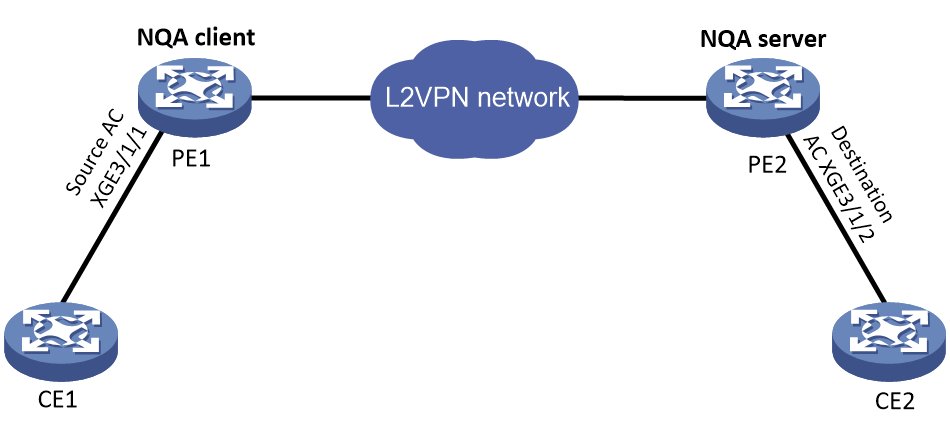
Procedure
1. Configure the L2VPN networking. (Details not shown.)
2. Configure PE2.
# Configure an NQA reflector on the NQA server for the Y.1564 operation.
<PE2> system-view
[PE2] nqa reflector 1 interface ten-gigabitethernet 3/1/2 service-instance 100 destination-port 20000 source-port 10000 destination-mac 2-2-2 source-mac 1-1-1
# Enable the NQA server.
[PE2] nqa server enable
3. Configure PE1.
# Create a Y.1564 operation.
<PE1> system-view
[PE1] nqa entry admin test1
[PE1-nqa-admin-test1] type y1564
# Specify 10000 as the source port number for the probe packets.
[PE1-nqa-admin-test1-y1564] source port 10000
# Specify 20000 as the destination port number for the probe packets.
[PE1-nqa-admin-test1-y1564] destination port 20000
# Specify 1-1-1 as the source MAC address for the probe packets.
[PE1-nqa-admin-test1-y1564] source mac 1-1-1
# Specify 2-2-2 as the source MAC address for the probe packets.
[PE1-nqa-admin-test1-y1564] destination mac 2-2-2
# Specify GigabitEthernet 1/0/1 as the source interface for the probe packets.
[PE1-nqa-admin-test1-y1564] source interface ten-gigabitethernet 3/1/1 service-instance 100
# Configure the Y.1564 operation basic parameters.
[PE1-nqa-admin-test1-y1564] bandwidth cir 1000 pir 10
[PE1-nqa-admin-test1-y1564] allowed-jitter 1000
[PE1-nqa-admin-test1-y1564] allowed-frame-loss 10
[PE1-nqa-admin-test1-y1564] allowed-transfer-delay 1000
# Enable the traffic policing test.
[PE1-nqa-admin-test1-y1564] traffic-policing-test enable
# Start the Y.1564 operation.
[PE1-nqa-admin-test1-y1564] start
[PE1-nqa-admin-test1-y1564] quit
The operation duration relates to the configured test items and the item duration.
Verifying the configuration
# Display the result of the Y.1564 operation.
[PE1] display nqa result
NQA entry (admin 1, tag 1) test results:
Status : Failed
Last test : Traffic policing test
Estimated total time (s) : 909
Actual test time used (s) : 9
Detailed test results:
CIR test (with the step of 1):
Start time : 2018-11-03 13:47:09.1
End time : 2018-11-03 13:47:12.1
Status : Succeeded
Min/Max/Average IR (kbps) : 998/1002/1000
Min/Max/Average FTD (us) : 232/236/234
Min/Max/Average FDV (us) : 32/36/34
FL count/FLR : 2/0.002%
Packets out of order : 0
Severely Err Secs/AVAIL : 0/100.000%
PIR test (color-blind):
Start time : 2018-11-03 13:47:12.1
End time : 2018-11-03 13:47:15.1
Status : Succeeded
Min/Max/Average IR (kbps) : 1008/1012/1010
Min/Max/Average FTD (us) : 235/239/237
Min/Max/Average FDV (us) : 35/39/37
FL count/FLR : 2/0.002%
Packets out of order : 0
Severely Err Secs/AVAIL : 0/100.000%
Traffic policing test (color-blind):
Start time : 2018-11-03 13:47:15.1
End time : 2018-11-03 13:47:18.1
Status : Failed
Min/Max/Average IR (kbps) : 943/947/945
Min/Max/Average FTD (us) : 294/298/296
Min/Max/Average FDV (us) : 94/98/96
FL count/FLR : 4/0.004%
Packets out of order : 0
Severely Err Secs/AVAIL : 0/100.000%
Example: Configuring Y.1564 operation on an L3VPN network
Network configuration
As shown in Figure 22, configure a Y.1564 operation to test the service quality from PE1 to PE2 over an L3VPN network.
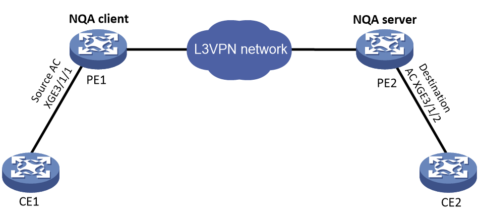
Procedure
1. Configure the L3VPN networking. (Details not shown.)
2. Configure PE2.
# Configure an NQA reflector on the NQA server for the Y.1564 operation.
<PE2> system-view
[PE2] nqa reflector 1 interface ten-gigabitethernet 3/1/2 ip destination 10.2.2.2 source 10.1.1.1 destination-port 20000 source-port 10000 vpn-instance vpn1
# Enable the NQA server.
[PE2] nqa server enable
3. Configure PE1.
# Create a Y.1564 operation.
<PE1> system-view
[PE1] nqa entry admin test1
[PE1-nqa-admin-test1] type y1564
# Specify 10.1.1.1 as the source IP address for the probe packets.
[PE1-nqa-admin-test1-y1564] source ip 10.1.1.1
# Specify 10.2.2.2 as the destination IP address for the probe packets.
[PE1-nqa-admin-test1-y1564] destination ip 10.2.2.2
# Specify 10000 as the source port number for the probe packets.
[PE1-nqa-admin-test1-y1564] source port 10000
# Specify 20000 as the destination port number for the probe packets.
[PE1-nqa-admin-test1-y1564] destination port 20000
# Specify GigabitEthernet 1/0/1 as the source interface for the probe packets.
[PE1-nqa-admin-test1-y1564] source interface ten-gigabitethernet 3/1/1
# Configure the Y.1564 operation basic parameters.
[PE1-nqa-admin-test1-y1564] bandwidth cir 100 pir 10000
[PE1-nqa-admin-test1-y1564] allowed-jitter 1000
[PE1-nqa-admin-test1-y1564] allowed-frame-loss 1000
[PE1-nqa-admin-test1-y1564] allowed-transfer-delay 1000
# Enable the traffic policing test.
[PE1-nqa-admin-test1-y1564] traffic-policing-test enable
# Start the Y.1564 operation.
[PE1-nqa-admin-test1-y1564] start
[PE1-nqa-admin-test1-y1564] quit
The operation duration relates to the configured test items and the item duration.
Verifying the configuration
# Display the result of the Y.1564 operation.
[PE1] display nqa result
NQA entry (admin admin, tag test1) test results:
Status : In progress
Last test : Traffic policing test
Estimated total time (s) : 909
Actual test time used (s) : 24
Detailed test results:
CIR test (with the step of 1):
Start time : 2018-11-03 13:44:16.1
End time : 2018-11-03 13:44:19.3
Status : Succeeded
Min/Max/Average IR (kbps) : 98/102/100
Min/Max/Average FTD (us) : 21/25/23
Min/Max/Average FDV (us) : 21/25/23
FL count/FLR : 2/0.002%
Packets out of order : 0
Severely Err Secs/AVAIL : 0/100.000%
PIR test (color-blind):
Start time : 2018-11-03 13:44:19.3
End time : 2018-11-03 13:44:22.5
Status : Succeeded
Min/Max/Average IR (kbps) : 10098/10102/10100
Min/Max/Average FTD (us) : 371/375/373
Min/Max/Average FDV (us) : 71/75/73
FL count/FLR : 7/0.007%
Packets out of order : 0
Severely Err Secs/AVAIL : 0/100.000%
Traffic policing test (color-blind):
Start time : 2018-11-03 13:44:22.5
End time : 2018-11-03 13:44:25.7
Status : Succeeded
Min/Max/Average IR (kbps) : 9448/9452/9450
Min/Max/Average FTD (us) : 958/962/960
Min/Max/Average FDV (us) : 58/62/60
FL count/FLR : 10/0.01%
Packets out of order : 0
Severely Err Secs/AVAIL : 0/100.000%
Example: Configuring Y.1564 operation on an L3VPN gateway
Network configuration
As shown in Figure 23, configure a Y.1564 operation to test the service quality from PE1 to CE1 over an L3VPN network.

Procedure
1. Configure the L3VPN network. (Details not shown.)
2. Configure CE1.
# Configure an NQA reflector on the NQA server for the Y.1564 operation.
<CE1> system-view
[CE1] nqa reflector 1 interface ten-gigabitethernet 3/1/1 ip destination 10.2.2.2 source 10.1.1.1 destination-port 20000 source-port 10000
# Enable the NQA server.
[CE1] nqa server enable
3. Configure PE1.
# Create a Y.1564 operation.
<PE1> system-view
[PE1] nqa entry admin test1
[PE1-nqa-admin-test1] type y1564
# Specify the gateway IP address (10.1.1.1) as the source IP address for the probe packets.
[PE1-nqa-admin-test1-y1564] source ip 10.1.1.1
# Specify 10.2.2.2 as the destination IP address for the probe packets.
[PE1-nqa-admin-test1-y1564] destination ip 10.2.2.2
# Specify 10000 as the source port number for the probe packets.
[PE1-nqa-admin-test1-y1564] source port 10000
# Specify 20000 as the destination port number for the probe packets.
[PE1-nqa-admin-test1-y1564] destination port 20000
# Specify GigabitEthernet 1/0/1 as the source interface for the probe packets.
[PE1-nqa-admin-test1-y1564] out interface ten-gigabitethernet 3/1/1
# Configure the Y.1564 operation basic parameters.
[PE1-nqa-admin-test1-y1564] bandwidth cir 100 pir 10000
[PE1-nqa-admin-test1-y1564] allowed-jitter 1000
[PE1-nqa-admin-test1-y1564] allowed-frame-loss 1000
[PE1-nqa-admin-test1-y1564] allowed-transfer-delay 1000
# Enable the traffic policing test.
[PE1-nqa-admin-test1-y1564] traffic-policing-test enable
# Start the Y.1564 operation.
[PE1-nqa-admin-test1-y1564] start
[PE1-nqa-admin-test1-y1564] quit
The operation duration relates to the configured test items and the item duration.
Verifying the configuration
# Display the result of the Y.1564 operation.
[PE1] display nqa result
NQA entry (admin admin, tag test1) test results:
Status : In progress
Last test : Traffic policing test
Estimated total time (s) : 909
Actual test time used (s) : 24
Detailed test results:
CIR test (with the step of 1):
Start time : 2018-11-03 14:44:16.1
End time : 2018-11-03 14:44:19.3
Status : Succeeded
Min/Max/Average IR (kbps) : 98/102/100
Min/Max/Average FTD (us) : 31/35/33
Min/Max/Average FDV (us) : 31/35/33
FL count/FLR : 5/0.005%
Packets out of order : 0
Severely Err Secs/AVAIL : 0/100.000%
PIR test (color-blind):
Start time : 2018-11-03 14:44:19.3
End time : 2018-11-03 14:44:22.5
Status : Succeeded
Min/Max/Average IR (kbps) : 10198/10202/10200
Min/Max/Average FTD (us) : 383/386/384
Min/Max/Average FDV (us) : 71/75/73
FL count/FLR : 7/0.007%
Packets out of order : 0
Severely Err Secs/AVAIL : 0/100.000%
Traffic policing test (color-blind):
Start time : 2018-11-03 14:44:22.5
End time : 2018-11-03 14:44:25.7
Status : Succeeded
Min/Max/Average IR (kbps) : 9563/9568/9566
Min/Max/Average FTD (us) : 876/985/980
Min/Max/Average FDV (us) : 58/62/60
FL count/FLR : 10/0.01%
Packets out of order : 0
Severely Err Secs/AVAIL : 0/100.000%
Example: Configuring Y.1564 operation on an L3VPN Network through an L2VPN
Network configuration
As shown in Figure 24, configure a Y.1564 operation to test the service quality from PE1 on an L2VPN network to PE2 on an L3VPN network.
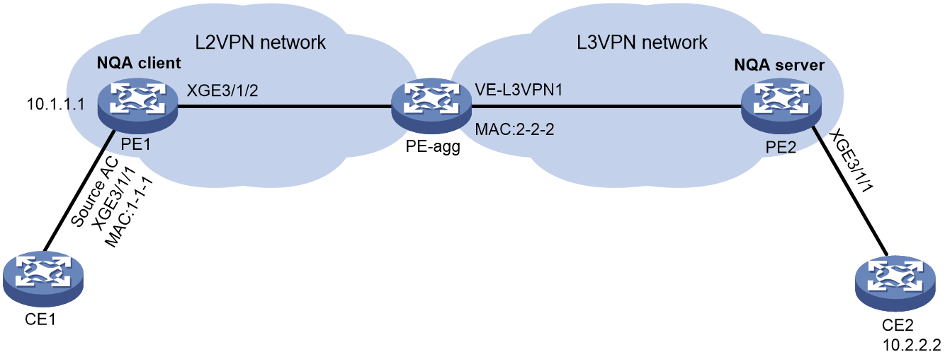
Procedure
1. Configure the L2VPN and L3VPN network. (Details not shown.)
2. Configure PE2.
# Configure an NQA reflector on the NQA server for the Y.1564 operation.
<PE2> system-view
[PE2] nqa reflector 1 interface ten-gigabitethernet 3/1/1 service-instance 100 ip destination 10.2.2.2 source 10.1.1.1 destination-port 20000 source-port 10000
# Enable the NQA server.
[PE2] nqa server enable
3. Configure PE1.
# Create a Y.1564 operation.
<PE1> system-view
[PE1] nqa entry admin test1
[PE1-nqa-admin-test1] type y1564
# Specify 10.1.1.1 as the source IP address for the probe packets.
[PE1-nqa-admin-test1-y1564] source ip 10.1.1.1
# Specify 10.2.2.2 as the destination IP address for the probe packets.
[PE1-nqa-admin-test1-y1564] destination ip 10.2.2.2
# Specify 10000 as the source port number for the probe packets.
[PE1-nqa-admin-test1-y1564] source port 10000
# Specify 20000 as the destination port number for the probe packets.
[PE1-nqa-admin-test1-y1564] destination port 20000
# Specify 1-1-1 as the source MAC address for the probe packets.
[PE1-nqa-admin-test1-y1564] source mac 1-1-1
# Specify the MAC address of the VE-L3VPN1 interface (2-2-2) as the destination MAC address for the probe packets.
[PE1-nqa-admin-test1-y1564] destination mac 2-2-2
# Specify GigabitEthernet 1/0/1 as the source interface for the probe packets.
[PE1-nqa-admin-test1-y1564] source interface ten-gigabitethernet 3/1/1 service-instance 100
# Configure the Y.1564 operation basic parameters.
[PE1-nqa-admin-test1-y1564] bandwidth cir 100 pir 10000
[PE1-nqa-admin-test1-y1564] allowed-jitter 1000
[PE1-nqa-admin-test1-y1564] allowed-frame-loss 1000
[PE1-nqa-admin-test1-y1564] allowed-transfer-delay 1000
# Enable the traffic policing test.
[PE1-nqa-admin-test1-y1564] traffic-policing-test enable
# Start the Y.1564 operation.
[PE1-nqa-admin-test1-y1564] start
[PE1-nqa-admin-test1-y1564] quit
The operation duration relates to the configured test items and the item duration.
Verifying the configuration
# Display the result of the Y.1564 operation.
[PE1] display nqa result
NQA entry (admin admin, tag test1) test results:
Status : In progress
Last test : Traffic policing test
Estimated total time (s) : 909
Actual test time used (s) : 24
Detailed test results:
CIR test (with the step of 1):
Start time : 2018-11-03 15:10:16.1
End time : 2018-11-03 15:10:19.3
Status : Succeeded
Min/Max/Average IR (kbps) : 87/132/105
Min/Max/Average FTD (us) : 31/35/33
Min/Max/Average FDV (us) : 41/45/43
FL count/FLR : 3/0.003%
Packets out of order : 0
Severely Err Secs/AVAIL : 0/100.000%
PIR test (color-blind):
Start time : 2018-11-03 15:10:19.3
End time : 2018-11-03 15:10:22.5
Status : Succeeded
Min/Max/Average IR (kbps) : 10098/10102/10100
Min/Max/Average FTD (us) : 321/384/353
Min/Max/Average FDV (us) : 81/85/83
FL count/FLR : 7/0.007%
Packets out of order : 0
Severely Err Secs/AVAIL : 0/100.000%
Traffic policing test (color-blind):
Start time : 2018-11-03 15:10:22.5
End time : 2018-11-03 15:10:25.7
Status : Succeeded
Min/Max/Average IR (kbps) : 6338/7563/6980
Min/Max/Average FTD (us) : 945/987/960
Min/Max/Average FDV (us) : 58/62/60
FL count/FLR : 10/0.01%
Packets out of order : 0
Severely Err Secs/AVAIL : 0/100.000%
Example: Configuring Y.1564 operation on an L3VPN gateway through an L2VPN
Network configuration
As shown in Figure 25, configure a Y.1564 operation to test the service quality from PE-agg on an L3VPN network to PE1 on an L2VPN network.
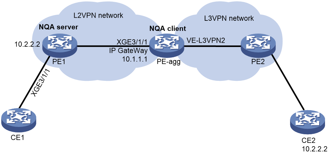
Procedure
1. Configure the L2VPN and L3VPN networks. (Details not shown.)
2. Configure PE1.
# Configure an NQA reflector on the NQA server for the Y.1564 operation.
<PE1> system-view
[PE1] nqa reflector 1 interface ten-gigabitethernet 3/1/1 ip destination 10.2.2.2 source 10.1.1.1 destination-port 20000 source-port 10000
# Enable the NQA server.
[PE1] nqa server enable
3. Configure PE-agg.
# Create a Y.1564 operation.
<PE-agg> system-view
[PE-agg] nqa entry admin test1
[PE-agg-nqa-admin-test1] type y1564
# Specify the gateway IP address (10.1.1.1) as the source IP address for the probe packets.
[PE-agg-nqa-admin-test1-y1564] source ip 10.1.1.1
# Specify 10.2.2.2 as the destination IP address for the probe packets.
[PE-agg-nqa-admin-test1-y1564] destination ip 10.2.2.2
# Specify 10000 as the source port number for the probe packets.
[PE-agg-nqa-admin-test1-y1564] source port 10000
# Specify 20000 as the destination port number for the probe packets.
[PE-agg-nqa-admin-test1-y1564] destination port 20000
# Specify GigabitEthernet 1/0/1 as the source interface for the probe packets.
[PE-agg-nqa-admin-test1-y1564] out interface VE-L3VPN2
# Configure the Y.1564 operation basic parameters.
[PE-agg-nqa-admin-test1-y1564] bandwidth cir 100 pir 10000
[PE-agg-nqa-admin-test1-y1564] allowed-jitter 1000
[PE-agg-nqa-admin-test1-y1564] allowed-frame-loss 1000
[PE-agg-nqa-admin-test1-y1564] allowed-transfer-delay 1000
# Enable the traffic policing test.
[PE-nqa-admin-test1-y1564] traffic-policing-test enable
# Start the Y.1564 operation.
[PE-agg-nqa-admin-test1-y1564] start
[PE-agg-nqa-admin-test1-y1564] quit
The operation duration relates to the configured test items and the item duration.
Verifying the configuration
# Display the result of the Y.1564 operation.
[PE-agg] display nqa result
NQA entry (admin admin, tag test1) test results:
Status : In progress
Last test : Traffic policing test
Estimated total time (s) : 909
Actual test time used (s) : 24
Detailed test results:
CIR test (with the step of 1):
Start time : 2018-11-03 15:44:16.1
End time : 2018-11-03 15:44:19.3
Status : Succeeded
Min/Max/Average IR (kbps) : 58/82/68
Min/Max/Average FTD (us) : 21/25/23
Min/Max/Average FDV (us) : 21/25/23
FL count/FLR : 2/0.002%
Packets out of order : 0
Severely Err Secs/AVAIL : 0/100.000%
PIR test (color-blind):
Start time : 2018-11-03 15:44:19.3
End time : 2018-11-03 15:44:22.5
Status : Succeeded
Min/Max/Average IR (kbps) : 10123/10234/10187
Min/Max/Average FTD (us) : 371/375/373
Min/Max/Average FDV (us) : 71/75/73
FL count/FLR : 7/0.007%
Packets out of order : 0
Severely Err Secs/AVAIL : 0/100.000%
Traffic policing test (color-blind):
Start time : 2018-11-03 15:44:22.5
End time : 2018-11-03 15:44:25.7
Status : Succeeded
Min/Max/Average IR (kbps) : 8328/8769/8654
Min/Max/Average FTD (us) : 738/762/740
Min/Max/Average FDV (us) : 58/62/60
FL count/FLR : 10/0.01%
Packets out of order : 0
Severely Err Secs/AVAIL : 0/100.000%
Example: Configuring NQA collaboration
Network configuration
As shown in Figure 26, configure a static route to Router C with Router B as the next hop on Router A. Associate the static route, a track entry, and an ICMP echo operation to monitor the state of the static route.
Procedure
1. Assign IP addresses to interfaces, as shown in Figure 26. (Details not shown.)
2. On Router A, configure a static route, and associate the static route with track entry 1.
<RouterA> system-view
[RouterA] ip route-static 10.1.1.2 24 10.2.1.1 track 1
3. On Router A, configure an ICMP echo operation:
# Create an NQA operation with administrator name admin and operation tag test1.
[RouterA] nqa entry admin test1
# Set the NQA operation type to ICMP echo.
[RouterA-nqa-admin-test1] type icmp-echo
# Specify 10.2.1.1 as the destination IP address.
[RouterA-nqa-admin-test1-icmp-echo] destination ip 10.2.1.1
# Configure the operation to repeat every 100 milliseconds.
[RouterA-nqa-admin-test1-icmp-echo] frequency 100
# Create reaction entry 1. If the number of consecutive probe failures reaches 5, collaboration is triggered.
[RouterA-nqa-admin-test1-icmp-echo] reaction 1 checked-element probe-fail threshold-type consecutive 5 action-type trigger-only
[RouterA-nqa-admin-test1-icmp-echo] quit
# Start the ICMP echo operation.
[RouterA] nqa schedule admin test1 start-time now lifetime forever
4. On Router A, create track entry 1, and associate it with reaction entry 1 of the NQA operation.
[RouterA] track 1 nqa entry admin test1 reaction 1
Verifying the configuration
# Display information about all the track entries on Router A.
[RouterA] display track all
Track ID: 1
State: Positive
Duration: 0 days 0 hours 0 minutes 0 seconds
Notification delay: Positive 0, Negative 0 (in seconds)
Tracked object:
NQA entry: admin test1
Reaction: 1
# Display brief information about active routes in the routing table on Router A.
[RouterA] display ip routing-table
Destinations : 11 Routes : 11
Destination/Mask Proto Pre Cost NextHop Interface
0.0.0.0/32 Direct 0 0 127.0.0.1 InLoop0
10.1.1.0/24 Static 60 0 10.2.1.1 XGE3/1/1
10.2.1.0/24 Direct 0 0 10.2.1.2 XGE3/1/1
10.2.1.0/32 Direct 0 0 10.2.1.2 XGE3/1/1
10.2.1.2/32 Direct 0 0 127.0.0.1 InLoop0
10.2.1.255/32 Direct 0 0 10.2.1.2 XGE3/1/1
127.0.0.0/8 Direct 0 0 127.0.0.1 InLoop0
127.0.0.0/32 Direct 0 0 127.0.0.1 InLoop0
127.0.0.1/32 Direct 0 0 127.0.0.1 InLoop0
127.255.255.255/32 Direct 0 0 127.0.0.1 InLoop0
255.255.255.255/32 Direct 0 0 127.0.0.1 InLoop0
The output shows that the static route with the next hop 10.2.1.1 is active, and the status of the track entry is positive.
# Remove the IP address of Ten-GigabitEthernet 3/1/1 on Router B.
<RouterB> system-view
[RouterB] interface ten-gigabitethernet 3/1/1
[RouterB-Ten-GigabitEthernet3/1/1] undo ip address
# Display information about all the track entries on Router A.
[RouterA] display track all
Track ID: 1
State: Negative
Duration: 0 days 0 hours 0 minutes 0 seconds
Notification delay: Positive 0, Negative 0 (in seconds)
Tracked object:
NQA entry: admin test1
Reaction: 1
# Display brief information about active routes in the routing table on Router A.
[RouterA] display ip routing-table
Destinations : 10 Routes : 10
Destination/Mask Proto Pre Cost NextHop Interface
0.0.0.0/32 Direct 0 0 127.0.0.1 InLoop0
10.2.1.0/24 Direct 0 0 10.2.1.2 XGE3/1/1
10.2.1.0/32 Direct 0 0 10.2.1.2 XGE3/1/1
10.2.1.2/32 Direct 0 0 127.0.0.1 InLoop0
10.2.1.255/32 Direct 0 0 10.2.1.2 XGE3/1/1
127.0.0.0/8 Direct 0 0 127.0.0.1 InLoop0
127.0.0.0/32 Direct 0 0 127.0.0.1 InLoop0
127.0.0.1/32 Direct 0 0 127.0.0.1 InLoop0
127.255.255.255/32 Direct 0 0 127.0.0.1 InLoop0
255.255.255.255/32 Direct 0 0 127.0.0.1 InLoop0
The output shows that the static route does not exist, and the status of the track entry is negative.
NQA template configuration examples
Example: Configuring the ARP template
Network configuration
As shown in Figure 27, configure an ARP template for a feature to perform the ARP operation to determine the availability of the ARP service on Device B.

Procedure
# Assign IP addresses to interfaces, as shown in Figure 27. (Details not shown.)
# Configure static routes or a routing protocol to make sure the devices can reach each other. (Details not shown.)
# Create ARP template arp.
<DeviceA> system-view
[DeviceA] nqa template arp arp
# Specify 10.1.1.2 as the destination IP address for the probe packets.
[DeviceA-nqatplt-arp-arp] destination ip 10.1.1.2
# Configure the NQA client to notify the feature of the successful operation event if the number of consecutive successful probes reaches 2.
[DeviceA-nqatplt-arp-arp] reaction trigger probe-pass 2
# Configure the NQA client to notify the feature of the operation failure if the number of consecutive failed probes reaches 2.
[DeviceA-nqatplt-arp-arp] reaction trigger probe-fail 2
[DeviceA-nqatplt-arp-arp] quit
Example: Configuring the ICMP template
Network configuration
As shown in Figure 28, configure an ICMP template for a feature to perform the ICMP echo operation from Device A to Device B.

Procedure
# Assign IP addresses to interfaces, as shown in Figure 28. (Details not shown.)
# Configure static routes or a routing protocol to make sure the devices can reach each other. (Details not shown.)
# Create ICMP template icmp.
<DeviceA> system-view
[DeviceA] nqa template icmp icmp
# Specify 10.2.2.2 as the destination IP address of ICMP echo requests.
[DeviceA-nqatplt-icmp-icmp] destination ip 10.2.2.2
# Set the probe timeout time to 500 milliseconds for the ICMP echo operation.
[DeviceA-nqatplt-icmp-icmp] probe timeout 500
# Configure the ICMP echo operation to repeat every 3000 milliseconds.
[DeviceA-nqatplt-icmp-icmp] frequency 3000
# Configure the NQA client to notify the feature of the successful operation event if the number of consecutive successful probes reaches 2.
[DeviceA-nqatplt-icmp-icmp] reaction trigger probe-pass 2
# Configure the NQA client to notify the feature of the operation failure if the number of consecutive failed probes reaches 2.
[DeviceA-nqatplt-icmp-icmp] reaction trigger probe-fail 2
[DeviceA-nqatplt-icmp-icmp] quit
Example: Configuring the IMAP template
Network configuration
As shown in Figure 29, configure an IMAP template for a feature to perform the IMAP operation to determine the availability of the IMAP service on Device B.
In the IMAP operation, the NQA client will try to log in to the mailbox named test by using username admin and password 123456.

Procedure
# Assign IP addresses to interfaces, as shown in Figure 29. (Details not shown.)
# Configure static routes or a routing protocol to make sure the devices can reach each other. (Details not shown.)
# Create IMAP template imap.
<DeviceA> system-view
[DeviceA] nqa template imap imap
# Specify 10.2.2.2 as the destination IP address for the probe packets.
[DeviceA-nqatplt-imap-imap] destination ip 10.2.2.2
# Specify the login username and password.
[DeviceA-nqatplt-imap-imap] username admin
[DeviceA-nqatplt-imap-imap] password simple 123456
# Specify test as the mailbox name used for the IMAP operation.
[DeviceA-nqatplt-imap-imap] mailbox test
# Configure the NQA client to notify the feature of the successful operation event if the number of consecutive successful probes reaches 2.
[DeviceA-nqatplt-imap-imap] reaction trigger probe-pass 2
# Configure the NQA client to notify the feature of the operation failure if the number of consecutive failed probes reaches 2.
[DeviceA-nqatplt-imap-imap] reaction trigger probe-fail 2
[DeviceA-nqatplt-imap-imap] quit
Example: Configuring the DNS template
Network configuration
As shown in Figure 30, configure a DNS template for a feature to perform the DNS operation. The operation tests whether Device A can perform the address resolution through the DNS server.

Procedure
# Assign IP addresses to interfaces, as shown in Figure 30. (Details not shown.)
# Configure static routes or a routing protocol to make sure the devices can reach each other. (Details not shown.)
# Create DNS template dns.
<DeviceA> system-view
[DeviceA] nqa template dns dns
# Specify the IP address of the DNS server (10.2.2.2) as the destination IP address.
[DeviceA-nqatplt-dns-dns] destination ip 10.2.2.2
# Specify host.com as the domain name to be translated.
[DeviceA-nqatplt-dns-dns] resolve-target host.com
# Set the domain name resolution type to type A.
[DeviceA-nqatplt-dns-dns] resolve-type A
# Specify 3.3.3.3 as the expected IP address.
[DeviceA-nqatplt-dns-dns] expect ip 3.3.3.3
# Configure the NQA client to notify the feature of the successful operation event if the number of consecutive successful probes reaches 2.
[DeviceA-nqatplt-dns-dns] reaction trigger probe-pass 2
# Configure the NQA client to notify the feature of the operation failure if the number of consecutive failed probes reaches 2.
[DeviceA-nqatplt-dns-dns] reaction trigger probe-fail 2
[DeviceA-nqatplt-dns-dns] quit
Example: Configuring the POP3 template
Network configuration
As shown in Figure 31, configure a POP3 template for a feature to perform the POP3 operation to determine the availability of the POP3 service on Device B.
In the POP3 operation, the NQA client will try to log in to the POP3 server on Device B by using username admin and password 123456.

Procedure
# Assign IP addresses to interfaces, as shown in Figure 31. (Details not shown.)
# Configure static routes or a routing protocol to make sure the devices can reach each other. (Details not shown.)
# Create POP3 template imap.
<DeviceA> system-view
[DeviceA] nqa template pop3 pop3
# Specify 10.2.2.2 as the destination IP address for the probe packets.
[DeviceA-nqatplt-pop3-pop3] destination ip 10.2.2.2
# Specify the login username and password.
[DeviceA-nqatplt-pop3-pop3] username admin
[DeviceA-nqatplt-pop3-pop3] password simple 123456
# Configure the NQA client to notify the feature of the successful operation event if the number of consecutive successful probes reaches 2.
[DeviceA-nqatplt-pop3-pop3] reaction trigger probe-pass 2
# Configure the NQA client to notify the feature of the operation failure if the number of consecutive failed probes reaches 2.
[DeviceA-nqatplt-pop3-pop3] reaction trigger probe-fail 2
[DeviceA-nqatplt-pop3-pop3] quit
Example: Configuring the SMTP template
Network configuration
As shown in Figure 32, configure an SMTP template for a feature to perform the SMTP operation to test whether the NQA client can log in to the mailbox on the SMTP server.
In the SMTP operation, the NQA client will try to log in to the SMTP server on Device B by using username admin and password 123456.

Procedure
# Assign IP addresses to interfaces, as shown in Figure 32. (Details not shown.)
# Configure static routes or a routing protocol to make sure the devices can reach each other. (Details not shown.)
# Create SMTP template smtp.
<DeviceA>system-view
[DeviceA] nqa template smtp smtp
# Specify 10.2.2.2 as the destination IP address for the probe packets.
[DeviceA-nqatplt-smtp-smtp] destination ip 10.2.2.2
# Configure the NQA client to notify the feature of the successful operation event if the number of consecutive successful probes reaches 2.
[DeviceA-nqatplt-smtp-smtp] reaction trigger probe-pass 2
# Configure the NQA client to notify the feature of the operation failure if the number of consecutive failed probes reaches 2.
[DeviceA-nqatplt-smtp-smtp] reaction trigger probe-fail 2
[DeviceA-nqatplt-smtp-smtp] quit
Example: Configuring the TCP template
Network configuration
As shown in Figure 33, configure a TCP template for a feature to perform the TCP operation. The operation tests whether Device A can establish a TCP connection to Device B.

Procedure
1. Assign IP addresses to interfaces, as shown in Figure 33. (Details not shown.)
2. Configure static routes or a routing protocol to make sure the devices can reach each other. (Details not shown.)
3. Configure Device B:
# Enable the NQA server.
<DeviceB> system-view
[DeviceB] nqa server enable
# Configure a listening service to listen to TCP port 9000 on IP address 10.2.2.2.
[DeviceB] nqa server tcp-connect 10.2.2.2 9000
4. Configure Device A:
# Create TCP template tcp.
<DeviceA> system-view
[DeviceA] nqa template tcp tcp
# Specify 10.2.2.2 as the destination IP address.
[DeviceA-nqatplt-tcp-tcp] destination ip 10.2.2.2
# Set the destination port number to 9000.
[DeviceA-nqatplt-tcp-tcp] destination port 9000
# Configure the NQA client to notify the feature of the successful operation event if the number of consecutive successful probes reaches 2.
[DeviceA-nqatplt-tcp-tcp] reaction trigger probe-pass 2
# Configure the NQA client to notify the feature of the operation failure if the number of consecutive failed probes reaches 2.
[DeviceA-nqatplt-tcp-tcp] reaction trigger probe-fail 2
[DeviceA-nqatplt-tcp-tcp] quit
Example: Configuring the TCP half open template
Network configuration
As shown in Figure 34, configure a TCP half open template for a feature to test whether Device B can provide the TCP service for Device A.

Procedure
# Assign IP addresses to interfaces, as shown in Figure 34. (Details not shown.)
# Configure static routes or a routing protocol to make sure the devices can reach each other. (Details not shown.)
# Create TCP half open template test.
<DeviceA> system-view
[DeviceA] nqa template tcphalfopen test
# Specify 10.2.2.2 as the destination IP address.
[DeviceA-nqatplt-tcphalfopen-test] destination ip 10.2.2.2
# Configure the NQA client to notify the feature of the successful operation event if the number of consecutive successful probes reaches 2.
[DeviceA-nqatplt-tcphalfopen-test] reaction trigger probe-pass 2
# Configure the NQA client to notify the feature of the operation failure if the number of consecutive failed probes reaches 2.
[DeviceA-nqatplt-tcphalfopen-test] reaction trigger probe-fail 2
[DeviceA-nqatplt-tcphalfopen-test] quit
Example: Configuring the UDP template
Network configuration
As shown in Figure 35, configure a UDP template for a feature to perform the UDP operation. The operation tests whether Device A can receive a response from Device B.

Procedure
1. Assign IP addresses to interfaces, as shown in Figure 35. (Details not shown.)
2. Configure static routes or a routing protocol to make sure the devices can reach each other. (Details not shown.)
3. Configure Device B:
# Enable the NQA server.
<DeviceB> system-view
[DeviceB] nqa server enable
# Configure a listening service to listen to UDP port 9000 on IP address 10.2.2.2.
[DeviceB] nqa server udp-echo 10.2.2.2 9000
4. Configure Device A:
# Create UDP template udp.
<DeviceA> system-view
[DeviceA] nqa template udp udp
# Specify 10.2.2.2 as the destination IP address.
[DeviceA-nqatplt-udp-udp] destination ip 10.2.2.2
# Set the destination port number to 9000.
[DeviceA-nqatplt-udp-udp] destination port 9000
# Configure the NQA client to notify the feature of the successful operation event if the number of consecutive successful probes reaches 2.
[DeviceA-nqatplt-udp-udp] reaction trigger probe-pass 2
# Configure the NQA client to notify the feature of the operation failure if the number of consecutive failed probes reaches 2.
[DeviceA-nqatplt-udp-udp] reaction trigger probe-fail 2
[DeviceA-nqatplt-udp-udp] quit
Example: Configuring the HTTP template
Network configuration
As shown in Figure 36, configure an HTTP template for a feature to perform the HTTP operation. The operation tests whether the NQA client can get data from the HTTP server.

Procedure
# Assign IP addresses to interfaces, as shown in Figure 36. (Details not shown.)
# Configure static routes or a routing protocol to make sure the devices can reach each other. (Details not shown.)
# Create HTTP template http.
<DeviceA> system-view
[DeviceA] nqa template http http
# Specify the URL of the HTTP server.
[DeviceA-nqatplt-http-http] url http://10.2.2.2/index.html
# Set the HTTP operation type to get.
[DeviceA-nqatplt-http-http] operation get
# Configure the NQA client to notify the feature of the successful operation event if the number of consecutive successful probes reaches 2.
[DeviceA-nqatplt-http-http] reaction trigger probe-pass 2
# Configure the NQA client to notify the feature of the operation failure if the number of consecutive failed probes reaches 2.
[DeviceA-nqatplt-http-http] reaction trigger probe-fail 2
[DeviceA-nqatplt-http-http] quit
Example: Configuring the HTTPS template
Network configuration
As shown in Figure 37, configure an HTTPS template for a feature to test whether the NQA client can get data from the HTTPS server (Device B).

Procedure
# Assign IP addresses to interfaces, as shown in Figure 37. (Details not shown.)
# Configure static routes or a routing protocol to make sure the devices can reach each other. (Details not shown.)
# Configure an SSL client policy named abc on Device A, and make sure Device A can use the policy to connect to the HTTPS server. (Details not shown.)
# Create HTTPS template test.
<DeviceA> system-view
[DeviceA] nqa template https https
# Specify the URL of the HTTPS server.
[DeviceA-nqatplt-https-https] url https://10.2.2.2/index.html
# Specify SSL client policy abc for the HTTPS template.
[DeviceA-nqatplt-https- https] ssl-client-policy abc
# Set the HTTPS operation type to get (the default HTTPS operation type).
[DeviceA-nqatplt-https-https] operation get
# Set the HTTPS version to 1.0 (the default HTTPS version).
[DeviceA-nqatplt-https-https] version v1.0
# Configure the NQA client to notify the feature of the successful operation event if the number of consecutive successful probes reaches 2.
[DeviceA-nqatplt-https-https] reaction trigger probe-pass 2
# Configure the NQA client to notify the feature of the operation failure if the number of consecutive failed probes reaches 2.
[DeviceA-nqatplt-https-https] reaction trigger probe-fail 2
[DeviceA-nqatplt-https-https] quit
Example: Configuring the FTP template
Network configuration
As shown in Figure 38, configure an FTP template for a feature to perform the FTP operation. The operation tests whether Device A can upload a file to the FTP server. The login username and password are admin and systemtest, respectively. The file to be transferred to the FTP server is config.txt.

Procedure
# Assign IP addresses to interfaces, as shown in Figure 38. (Details not shown.)
# Configure static routes or a routing protocol to make sure the devices can reach each other. (Details not shown.)
# Create FTP template ftp.
<DeviceA> system-view
[DeviceA] nqa template ftp ftp
# Specify the URL of the FTP server.
[DeviceA-nqatplt-ftp-ftp] url ftp://10.2.2.2
# Specify 10.1.1.1 as the source IP address.
[DeviceA-nqatplt-ftp-ftp] source ip 10.1.1.1
# Configure the device to upload file config.txt to the FTP server.
[DeviceA-nqatplt-ftp-ftp] operation put
[DeviceA-nqatplt-ftp-ftp] filename config.txt
# Set the username to admin for the FTP server login.
[DeviceA-nqatplt-ftp-ftp] username admin
# Set the password to systemtest for the FTP server login.
[DeviceA-nqatplt-ftp-ftp] password simple systemtest
# Configure the NQA client to notify the feature of the successful operation event if the number of consecutive successful probes reaches 2.
[DeviceA-nqatplt-ftp-ftp] reaction trigger probe-pass 2
# Configure the NQA client to notify the feature of the operation failure if the number of consecutive failed probes reaches 2.
[DeviceA-nqatplt-ftp-ftp] reaction trigger probe-fail 2
[DeviceA-nqatplt-ftp-ftp] quit
Example: Configuring the RADIUS template
Network configuration
As shown in Figure 39, configure a RADIUS template for a feature to test whether the RADIUS server (Device B) can provide authentication service for Device A. The username and password are admin and systemtest, respectively. The shared key is 123456 for secure RADIUS authentication.

Procedure
# Assign IP addresses to interfaces, as shown in Figure 39. (Details not shown.)
# Configure static routes or a routing protocol to make sure the devices can reach each other. (Details not shown.)
# Configure the RADIUS server. (Details not shown.)
# Create RADIUS template radius.
<DeviceA> system-view
[DeviceA] nqa template radius radius
# Specify 10.2.2.2 as the destination IP address of the operation.
[DeviceA-nqatplt-radius-radius] destination ip 10.2.2.2
# Set the username to admin.
[DeviceA-nqatplt-radius-radius] username admin
# Set the password to systemtest.
[DeviceA-nqatplt-radius-radius] password simple systemtest
# Set the shared key to 123456 in plain text for secure RADIUS authentication.
[DeviceA-nqatplt-radius-radius] key simple 123456
# Configure the NQA client to notify the feature of the successful operation event if the number of consecutive successful probes reaches 2.
[DeviceA-nqatplt-radius-radius] reaction trigger probe-pass 2
# Configure the NQA client to notify the feature of the operation failure if the number of consecutive failed probes reaches 2.
[DeviceA-nqatplt-radius-radius] reaction trigger probe-fail 2
[DeviceA-nqatplt-radius-radius] quit
Example: Configuring the SNMP template
Network configuration
As shown in Figure 40, configure an SNMP template to test the time the NQA client uses to get a response from the SNMP agent.

Procedure
1. Assign IP addresses to interfaces, as shown in Figure 40. (Details not shown.)
2. Configure static routes or a routing protocol to make sure the devices can reach each other. (Details not shown.)
3. Configure the SNMP agent (Device B):
# Set the SNMP version to all.
<DeviceB> system-view
[DeviceB] snmp-agent sys-info version all
# Set the read community to public.
[DeviceB] snmp-agent community read public
# Set the write community to private.
[DeviceB] snmp-agent community write private
4. Configure Device A:
# Create an SNMP template.
<DeviceA> system-view
[DeviceA] nqa template snmp snmp
# Specify the destination IP address and port number for the SNMP operation.
[DeviceA-nqatplt-snmp-snmp] destination ip 10.2.2.2
[DeviceA-nqatplt-snmp-snmp] destination port 161
# Set the read community to public.
[DeviceA-nqatplt-snmp-snmp] community read simple public
# Configure the NQA client to notify the feature of the successful operation event if the number of consecutive successful probes reaches 2.
[DeviceA-nqatplt-snmp-snmp] reaction trigger probe-pass 2
# Configure the NQA client to notify the feature of the operation failure if the number of consecutive failed probes reaches 2.
[DeviceA-nqatplt-snmp-snmp] reaction trigger probe-fail 2
[DeviceA-nqatplt-snmp-snmp] quit
Example: Configuring the SSL template
Network configuration
As shown in Figure 41, configure an SSL template for a feature to test whether Device A can establish an SSL connection to the SSL server on Device B.

Procedure
# Assign IP addresses to interfaces, as shown in Figure 41. (Details not shown.)
# Configure static routes or a routing protocol to make sure the devices can reach each other. (Details not shown.)
# Configure an SSL client policy named abc on Device A, and make sure Device A can use the policy to connect to the SSL server on Device B. (Details not shown.)
# Create SSL template ssl.
<DeviceA> system-view
[DeviceA] nqa template ssl ssl
# Set the destination IP address and port number to 10.2.2.2 and 9000, respectively.
[DeviceA-nqatplt-ssl-ssl] destination ip 10.2.2.2
[DeviceA-nqatplt-ssl-ssl] destination port 9000
# Specify SSL client policy abc for the SSL template.
[DeviceA-nqatplt-ssl-ssl] ssl-client-policy abc
# Configure the NQA client to notify the feature of the successful operation event if the number of consecutive successful probes reaches 2.
[DeviceA-nqatplt-ssl-ssl] reaction trigger probe-pass 2
# Configure the NQA client to notify the feature of the operation failure if the number of consecutive failed probes reaches 2.
[DeviceA-nqatplt-ssl-ssl] reaction trigger probe-fail 2
[DeviceA-nqatplt-ssl-ssl] quit
Configuring TWAMP
About TWAMP
Two-Way Active Measurement Protocol (TWAMP) defines a standard to measure the network performance between network devices on an IP network. It uses UDP packets to measure the two-way delay, jitter and packet loss ratio.
TWAMP architecture
TWAMP uses the client-server model.
On the client, the following roles are configured:
· TWAMP client—Initiates and manages TWAMP control sessions and negotiates the TWAMP test sessions.
· Session sender—Starts and stops TWAMP test sessions, and collect statistics. The TWAMP session sender is the source device of the TWAMP test.
On the server, the following roles are configured:
· TWAMP server—Receives and maintains TWAMP control sessions and negotiates the TWAMP test sessions.
· Session reflector—Reflects the test packet back to the TWAMP client. The TWAMP session reflector is the destination device of the TWAMP test.
The device can function as an IPv4 TWAMP server or IPv6 TWAMP server, not a TWAMP client. You can start multiple IPv4 TWAMP tests and IPv6 TWAMP tests as required.
TWAMP operating mechanism
Figure 42 shows the stages of a TWAMP test.
Establishing control sessions
1. Enable IPv4 TWAMP server or IPv6 TWAMP server on the NQA server to listen the connection requests of the NQA client.
2. After receiving a TCP connection request, the TWAMP server responds to the Server-Greeting message and listens to the TCP connection. The TWAMP server specifies unauthenticated as the mode filed in the message.
3. The TWAMP client sends a Set-Up-Response message to the TWAMP server through the TCP connection.
4. After verifying the unauthenticated mode in the Set-Up-Response message, the TWAMP server sends a Server-Start message containing TWAMP server start time to the TWAMP client.
A control session is established successfully.
Establishing test sessions
1. The TWAMP client sends a Request-TW-Session message to the TWAMP server through the established TCP connection, requesting to negotiate a test session. The Request-TW-Session message contains the sender port number, sender IP address, reflector port number, and reflector IP address.
2. After checking the legitimacy of the message, the TWAMP server sends an Accept-Session message to the TWAMP client. If the accept field in the message uses value OK, the test session negotiation succeeds and the session reflector is enabled in the control session.
Starting TWAMP test sessions
After a test session is established successfully, the TWAMP server waits for a Start-Session message from the TWAMP client to start the TWAMP test sessions.
After receiving the Start-Session message, the TWAMP server starts all test sessions managed by the control session and reflects the TWAMP client packets. If a test session is started successfully, the TWAMP server sends an ACK message to the TWAMP client.
Stopping TWAMP test sessions
After receiving a Stop-Session message, the TWAMP server stops all test sessions managed by the control session.
Figure 42 TWAMP operating mechanism
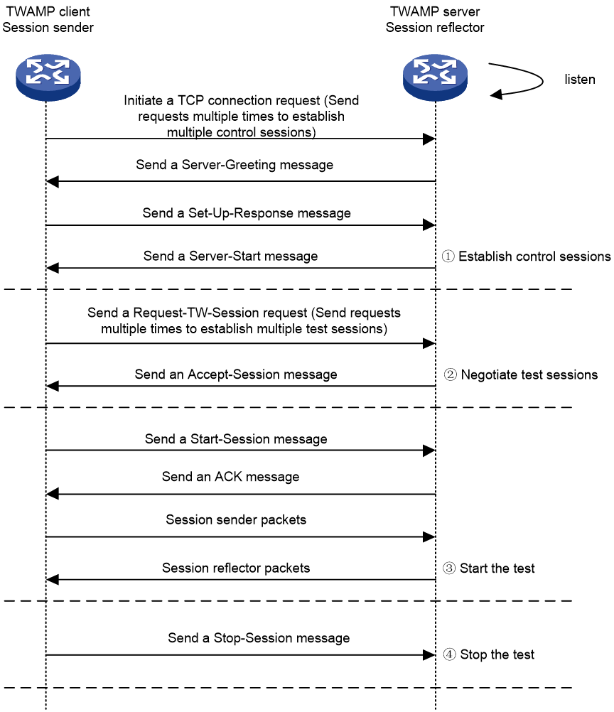
Protocols and standards
· RFC 5357, A Two-Way Active Measurement Protocol (TWAMP)
Restrictions and guidelines: TWAMP configuration
When a TWAMP client initiates multiple TWAMP tests simultaneously to the device, make sure the following conditions are met:
· For consequent tests to succeed after the first test, make sure the combination of the destination address, port number, and VPN instance for a control session is not completely the same as another control session.
· To avoid inaccurate test results caused by invalid service packets, make sure the combination of the destination address, port number, and VPN instance for a test session is not completely the same as another test session.
When performing a TWAMP test and a TWAMP Light test simultaneously on a device, make sure the combination of the destination address, port number, and VPN instance for one test is not completely the same as the other. This can avoid inaccurate test results caused by invalid service packets.
To avoid probe failures, follow these restrictions and guidelines when configuring the listening port on the TWAMP Light server:
· Do not specify a well-known port.
· Make sure the specified port number is not used by any services on the device.
¡ To obtain the IPv4 addresses and the port numbers in use on this device, see the Local Addr:port field in the output from the display tcp and display udp commands.
¡ To obtain the IPv6 addresses and the port numbers in use on this device, see the LAddr->port field in the output from the display ipv6 tcp and display ipv6 udp commands.
Configuring the TWAMP server
1. Enter system view.
system-view
2. Enable the TWAMP server and enter its view.
IPv4:
nqa twamp server
IPv6:
nqa twamp ipv6 server
By default, the TWAMP server is disabled.
3. (Optional.) Specify an ACL to control client access.
client acl { acl-number | name acl-name }
By default, no ACL is specified to control TWAMP client access.
4. Specify a timeout timer for TWAMP server control sessions.
control-session timeout timeout
By default, the timeout timer for TWAMP server control sessions is 900 seconds.
5. Specify a TCP port listened by the TWAMP server.
tcp port port-number [ all | vpn-instance vpn-instance-name ]
By default, the TCP port listened by the TWAMP server is 862.
Configuring the TWAMP reflector
1. Enter system view.
system-view
2. Enable the TWAMP reflector and enter its view.
nqa twamp reflector
By default, the TWAMP reflector is disabled.
3. Specify a timeout timer for TWAMP reflector test sessions.
test-session timeout timeout
By default, the timeout timer for TWAMP reflector test sessions is 900 seconds.
Display and maintenance commands for TWAMP
Execute display commands in any view on the TWAMP server.
|
Task |
Command |
|
Display session information about the TWAMP server. |
display nqa twamp [ipv6] server session [ all | vpn-instance vpn-instance-name [ source source-ip ] ] |
|
Display global information about the TWAMP server. |
display nqa twamp [ipv6] server global-information |
TWAMP configuration examples
Example: Configuring TWAMP test
Network configuration
As shown in Figure 43, configure a TWAMP test to measure the service quality from Device A to Device B.

Procedure
1. Assign IP addresses to interfaces, as shown in Figure 43. (Details not shown.)
2. Configure static routes or a routing protocol to make sure the devices can reach each other. (Details not shown.)
3. Configure the TWAMP Light client on Device A. For detailed configuration, see the related contents in the TWAMP Light test.
4. Configure Device B:
# Enable the NQA server.
<DeviceB> system-view
[DeviceB] nqa server enable
# Create a basic ACL numbered 2000 and configure a rule to permit access from the TWAMP client to the TWAMP server.
[DeviceB] acl basic 2000
[DeviceB-acl-ipv4-basic-2000] rule permit source 3.1.1.1 0.0.255.255
[DeviceB-acl-ipv4-basic-2000] quit
# Enable the TWAMP server and specify ACL 2000 for the TWAMP server.
[DeviceB] nqa twamp server
[DeviceB-nqa-twamp-server] client acl 2000
# Specify 1000 seconds as the timeout timer for TWAMP server control sessions.
[DeviceB-nqa-twamp-server] control-session timeout 1000
# Specify TCP port 862 to be listened by the TWAMP server.
[DeviceB-nqa-twamp-server] tcp port 862
[DeviceB-nqa-twamp-server] quit
# Enable the TWAMP reflector.
[DeviceB] nqa twamp reflector
# Specify 1000 seconds as the timeout timer for TWAMP reflector test sessions.
[DeviceB-nqa-twamp-reflector] test-session timeout 1000
Verifying the configuration
# Display session information about the TWAMP server.
[DeviceB-nqa-twamp-reflector] dislay nqa twamp server session
Connection entry 1:
Client address : 3.1.1.2
Client port : 63181
Server address : 3.1.1.1
Server port : 862
VPN instance : --
Mode : No Authentication
Created at : 2020-07-06 07:10:41.56
Connection state : Active
Test session 1:
Sender address : 3.1.1.2
Sender port : 5450
Reflector address : 3.1.1.1
Reflector port : 5450
DSCP : 0
Padding length : 128
Created at : 2020-06-24 21:05:09.2
Session ID : 3.1.1.1:3803078737-1127519109:1d58edb7
Sent probe packets : 252
Received probe packets: 252
Session state : Active
Configuring TWAMP Light
About TWAMP Light
Two-Way Active Measurement Protocol (TWAMP) defines a standard to measure the network performance between network devices on an IP network. It uses UDP packets to measure the two-way Frame Transfer Delay (FTD), Frame Delay Variation (FDV), and Frame Loss Ratio (FLR). The TWAMP Light provides a simple structure of TWAMP. It simplifies the control protocol for establishing performance measurement sessions and improves test performance.
TWAMP Light architecture
TWAMP Light uses the client-server model.
Figure 44 describes the TWAMP Light roles and the typical network diagram.
On the client, the following roles are configured:
· TWAMP Light client—Configures TWAMP Light test sessions.
· TWAMP Light sender—Starts and stops TWAMP Light test sessions, and collect statistics.
On the server, the TWAMP Light responder, also known as the destination device, is configured. The responder reflects the packets back to the TWAMP Light sender. You must enable the NQA server on the destination device, and create the TWAMP Light responder and test sessions.

TWAMP Light operating mechanism
A TWAMP Light test contains a set of parameters for a test session such as the source IP address and destination IP address.
Each TWAMP Light test session is uniquely identified by the test session ID. You can create and run multiple test sessions on one TWAMP Light client.
The TWAMP Light client and TWAMP Light responder interact as follows:
1. The TWAMP Light client constructs TWAMP Light test packets, and sends them to the TWAMP Light responder.
2. The TWAMP Light responder reflects the test packets to the TWAMP Light client.
3. Upon receiving the reflected packets, the TWAMP Light client calculates the packet loss ratio and round-trip time to determine the service quality from source to destination.
After a TWAMP Light test starts, the TWAMP light client runs the tests permanently or repeats the test at the specified interval. Each test sends one test packet. You can set the test duration and number of test packets to be sent.
Threshold monitoring
Threshold monitoring enables the TWAMP Light client to take a predefined action when the TWAMP Light test performance metrics violate the specified thresholds.
The TWAMP Light test monitors the following metrics:
· Two-way frame delay variation.
· Two-way frame transfer delay.
· Two-way frame loss rate.
In a TWAMP test, the device monitors the test result, and starts the monitoring time when either of the following conditions is met:
· The monitoring result goes beyond the threshold upper limit.
· The monitoring result drops below the threshold lower limit from a monitoring result higher than the lower limit.
If either condition is always true during the monitoring time, a threshold violation occurs and a trap or inform message is generated and sent to the NMS. You set the monitoring time by using the corresponding command.
Protocols and standards
· RFC 5357, A Two-Way Active Measurement Protocol (TWAMP)
Restrictions and guidelines: TWAMP Light configuration
In standard system operating mode, only the following cards support this feature:
CSPEX-1802X, CSPEX-1802XA, CSPEX-1812X-E, CSPEX-2304X-G, CEPC-CQ8L, CEPC-CQ8LA, CEPC-CQ16L1, CSPEX-1502XA, RX-SPE200-E
In SDN-WAN system operating mode, only the following cards support this feature:
CSPEX-1304X, CSPEX-1404X, CSPEX-1502X, CSPEX-1504X, CSPEX-1504XA, CSPEX-1602X, CSPEX-1602XA, CSPEX-1804X, CSPEX-1512X, CSPEX-1612X, CSPEX-1812X, RX-SPE200, CEPC-XP4LX, CEPC-XP24LX, CEPC-XP48RX, CEPC-CP4RX, CEPC-CP4RXA, CEPC-CP4RX-L, CSPEX-1802X, CSPEX-1802XA, CSPEX-1812X-E, CSPEX-2304X-G, CEPC-CQ8L, CEPC-CQ8LA, CEPC-CQ16L1, CSPEX-1502XA, RX-SPE200-E
If the test packet output interface of the TWAMP Light responder is on the following cards, you must configure the qos trust auto override command on the interface to ensure correct packet priority:
CSPEX-1802X, CSPEX-1802XA, CSPEX-1812X-E, CSPEX-2304X-G, CEPC-CQ8L, CEPC-CQ8LA, CEPC-CQ16L1, CSPEX-1502XA, RX-SPE200-E
For information about the qos trust command, see ACL and QoS Command Reference.
As a best practice to measure the two-way delay, configure the same timestamp format (PTP or NTP) for the two ends on the following cards:
CSPEX-1304X, CSPEX-1404X, CSPEX-1502X, CSPEX-1504X, CSPEX-1504XA, CSPEX-1602X, CSPEX-1602XA, CSPEX-1804X, CSPEX-1512X, CSPEX-1612X, CSPEX-1812X, RX-SPE200, CEPC-XP4LX, CEPC-XP24LX, CEPC-XP48RX, CEPC-CP4RX, CEPC-CP4RXA, CEPC-CP4RX-L
When performing a TWAMP test and a TWAMP Light test simultaneously on a device, make sure the combination of the destination address, port number, and VPN instance for one test is not completely the same as the other. This can avoid inaccurate test results caused by invalid service packets.
To avoid probe failures, follow these restrictions and guidelines when configuring the listening port on the TWAMP Light server and TWAMP Light client:
· Do not specify a well-known port.
· Make sure the specified port number is not used by any services on the device.
¡ To obtain the IPv4 addresses and the port numbers in use on this device, see the Local Addr:port field in the output from the display tcp and display udp commands.
¡ To obtain the IPv6 addresses and the port numbers in use on this device, see the LAddr->port field in the output from the display ipv6 tcp and display ipv6 udp commands.
The destination port configured for the operation (with the destination port command) on the TWAMP Light client must be the same as the listening port configured on the server.
TWAMP Light tasks at a glance
To configure TWAMP Light, perform the following tasks:
1. Configuring the TWAMP Light server
2. Configuring the TWAMP Light client
3. Start the test on the TWAMP Light sender
4. (Optional.) Stop the test on the TWAMP Light sender
Configuring the TWAMP Light server
Restrictions and guidelines
Enable checksum field adjustment for test packets in either of following ways:
· Enable the feature globally. The feature will take effect on all sessions to be created in TWAMP Light responder view, and will not affect existing sessions.
· Enable the feature by using the test-session command. The feature will take effect only on the session to start.
This feature applies only to IPv6 packets.
Procedure
1. Enter system view.
system-view
2. Enable the TWAMP Light responder on the NQA server and enter its view.
nqa twamp-light responder
3. Enable checksum field adjustment for test packets globally.
adjust-udp-checksum global enable
By default, checksum field adjustment for test packets is disabled globally.
4. Create a test session on the TWAMP Light responder.
test-session session-id [ interface interface-type interface-number [ service-instance instance-id ] ] [ link-bundle-interface interface-type interface-number ] { destination-mac mac-address source-mac mac-address | { ip | ipv6 } destination address source address destination-port port-number source-port port-number [ vpn-instance vpn-instance-name ] } * [ adjust-udp-checksum | description text | extended-packet | timestamp-format { ntp | ptp } | vlan { vlan-id | s-vid vlan-id c-vid vlan-id } ] *
5. Return to system view.
quit
6. Enable the NQA server.
nqa server enable
By default, the NQA server is disabled.
Configuring the TWAMP Light client
Restrictions and guidelines
In the TWAMP Light test, a test session is identified by the combination of its address and port number. To ensure the test result, you cannot specify the same combination of address and port number for multiple test sessions.
Enable checksum field adjustment for test packets in either of following ways:
· Enable the feature globally. The feature will take effect on all sessions to be created in TWAMP Light responder view, and will not affect existing sessions.
· Enable the feature by using the test-session command. The feature will take effect only on the session to start.
This feature applies only to IPv6 packets.
Enabling the NQA client
1. Enter system view.
system-view
2. Enable the NQA client.
nqa agent enable
By default, the NQA client is enabled.
After the NQA client is enabled, the TWAMP Light test session configuration can takes effect.
Enabling checksum field adjustment for test packets globally
1. Enter system view.
system-view
2. Enter TWAMP Light client view.
nqa twamp-light client
3. Enable checksum field adjustment for test packets globally.
adjust-udp-checksum global enable
By default, checksum field adjustment for test packets is disabled globally.
Creating a test session on the TWAMP Light client
1. Enter system view.
system-view
2. Enter TWAMP Light client view.
nqa twamp-light client
3. Create a test session on the TWAMP Light client and enter the client-session view.
test-session session-id
4. (Optional.) Specify the description for the probe packets.
description text
By default, no description is specified.
Configuring the IP address and port number for the TWAMP Light test session
1. Enter system view.
system-view
2. Enter TWAMP Light client view.
nqa twamp-light client
3. Enter TWAMP Light client test-session view.
test-session session-id
4. Specify the source IP address for the probe packets.
IPv4:
source ip ip-address
By default, no source IPv4 address for the probe packets is specified.
IPv6:
source ipv6 ipv6-address
By default, no source IPv6 address for the probe packets is specified.
5. Specify the destination IP address for the probe packets.
IPv4:
destination ip ipv4-address
By default, no destination IPv4 address for the probe packets is specified.
IPv6:
destination ipv6 ipv6-address
By default, no destination IPv6 address for the probe packets is specified.
6. Specify the source interface for the probe packets.
source interface interface-type interface-number [ service-instance instance-id ]
By default, no source interface for the probe packets is specified.
The specified source interface must be up.
7. Specify the source port number for the probe packets.
source port port-number
By default, no source port number for the probe packets is specified.
For TWAMP Light tests, you must configure this command. For the probe operation to succeed, make sure the specified port number is not used by any services on the device.
8. Specify the destination port number for the probe packets.
destination port port-number
By default, no destination port number for the probe packets is specified.
9. Specify the source MAC address for the probe packets.
source mac mac-address
By default, no source MAC address for the probe packets is specified.
10. Specify the destination MAC address for the probe packets.
destination mac mac-address
By default, no destination MAC address for the probe packets is specified.
11. (Optional.) Specify the VPN instance where the test is performed.
vpn-instance vpn-instance-name
By default, no VPN instance is specified. The test is performed on the public network.
Configuring other parameters for the TWAMP Light probe packets
1. Enter system view.
system-view
2. Enter TWAMP Light client view.
nqa twamp-light client
3. Enter TWAMP Light client test-session view.
test-session session-id
4. Specify the timestamp format for the TWAMP Light test session.
timestamp-format { ntp | ptp }
By default, the timestamp format for the TWAMP Light test is PTP.
5. Specify the payload parameters for the TWAMP Light test.
¡ Set the payload size for each probe packet.
data-size size
The default payload size is 142 bytes.
¡ Specify the payload fill string for each probe packet.
- data-fill string
- hex-data-fill hex
The two commands have the same function. If you execute them multiple times, the most recent configuration takes effect.
The default payload fill string is the hexadecimal string 00010203040506070809.
6. (Optional.) Specify the priority for the probe packets.
¡ Specify the 802.1p priority for the probe packets.
priority 8021p value
By default, the 802.1p priority of the probe packets is 0.
¡ Set the ToS value in the IP header of the probe packets.
tos value
The default setting is 0.
7. (Optional.) Specify the ID of the VLAN to which the probe packets belong.
vlan { vlan-id | s-vid vlan-id c-vid vlan-id }
By default, no VLAN ID is specified.
8. (Optional.) Bind an interface as the output interface for a TWAMP Light test session.
test-session session-id bind interface interface-type interface-number
By default, no interface is specified as the output interface for a TWAMP Light test session.
9. (Optional.) Enable checksum field adjustment for test packets.
adjust-udp-checksum enable
By default, checksum field adjustment for test packets is disabled.
Follow these restrictions when you configure this feature:
¡ The feature does not support mirroring the outgoing TWAMP Light probe packets.
¡ This feature supports only Layer 3 aggregate interfaces and Layer 3 aggregate subinterfaces.
¡ This feature does not support MPLS and SRv6 networks.
Enabling TWAMP Light for all member interfaces of an aggregate interface
About this task
By default, if the output interface for TWAMP Light probe packets is a Layer 3 aggregate interface or Layer 3 aggregate subinterface, the device automatically selects a member interface. The test is performed on the link associated with the member interface, but the test result will be used for measuring the quality of the entire aggregate link. After you configure this feature, the device performs the test on all member interfaces of the aggregate interface to measure the quality of links associated to all member interfaces.
Restrictions and guidelines
Make sure the TWAMP Light enabling state for all member interfaces of the aggregate interface is the same on the TWAMP Light client and TWAMP Light server. Otherwise, the TWAMP Light test might fail or the test result might be inaccurate.
Procedure
1. Enter system view.
system-view
2. Enter TWAMP Light client view.
nqa twamp-light client
3. Enter TWAMP Light client-session view.
test-session session-id
4. Enable TWAMP Light for all member interfaces of an aggregate interface.
link-bundle-interface interface-type interface-number
By default, TWAMP Light is disabled for all member interfaces of an aggregate interface.
Follow these restrictions when you configure this feature:
¡ The feature does not support mirroring the outgoing TWAMP Light probe packets.
¡ This feature supports only Layer 3 aggregate interfaces and Layer 3 aggregate subinterfaces.
¡ This feature does not support MPLS and SRv6 networks.
Enabling one-way delay measurement
About this task
By default, TWAMP Light measures two-way path delay, jitter, and packet loss rate. After you enable one-way delay measurement for a TWAMP Light session and start the session, TWAMP Light also measures delay on the following directions separately:
· From the TWAMP Light client to TWAMP Light server.
· From the TWAMP Light server to TWAMP Light client.
Restrictions and guidelines
You can use one-way delay-measure global enable or one-way delay-measure enable to enable one-way delay measurement for the TWAMP Light session. The one-way delay-measure global enable command applies to all new test sessions on the TWAMP Light client. The one-way delay-measure enable command applies to only the specified test session.
Procedure
1. Enter system view.
system-view
2. Enter TWAMP Light client view.
nqa twamp-light client
3. Enable one-way delay measurement for the TWAMP Light client.
one-way delay-measure global enable
By default, one-way delay measurement is disabled for the TWAMP Light client.
4. Enter TWAMP Light client-session view.
test-session session-id
5. Enable one-way delay measurement for the TWAMP Light session.
one-way delay-measure enable
By default, one-way delay measurement is disabled for a TWAMP Light session.
Configuring threshold monitoring
1. Enter system view.
system-view
2. Enable the TWAMP Light client and enter its view.
nqa twamp-light client
3. Create a test session on the TWAMP Light client and enter the client-session view.
test-session session-id
4. Configure a reaction entry. Choose the following tasks as needed:
¡ Configure a reaction entry for monitoring the two-way delay.
reaction item-number checked-element two-way-delay threshold-value upper-threshold lower-threshold [ action-type { none | trap-only } ]
By default, no reaction entry is configured for monitoring the two-way delay.
¡ Configure a reaction entry for monitoring the two-way packet loss.
reaction item-number checked-element two-way-loss threshold-value upper-threshold lower-threshold [ action-type { none | trap-only } ]
By default, no reaction entry is configured for monitoring the two-way packet loss.
¡ Configure a reaction entry for monitoring the two-way jitter.
reaction item-number checked-element two-way-jitter threshold-value upper-threshold lower-threshold [ action-type { none | trap-only } ]
By default, no reaction entry is configured for monitoring the two-way jitter.
Start the test on the TWAMP Light sender
Restrictions and guidelines
In the TWAMP Light test, a test session is identified by the combination of source IP address, source port number, destination IP address, and destination port number. To ensure the test result, do not specify the same combination for multiple test sessions.
With the data-fill command configured, the packet sending interval cannot be 10 or 100 milliseconds.
Procedure
1. Enter system view.
system-view
2. Enable the TWAMP Light sender and enter its view.
nqa twamp-light sender
3. Start a TWAMP Light test.
start test-session session-id { permanent | duration duration | packet-count count } [ tx-interval { 10 | 100 | 1000 | 10000 | 30000 } ] [ time-out timeout ] [ [ statistics-interval statistics-interval ] monitor-time time ]
Stop the test on the TWAMP Light sender
1. Enter system view.
system-view
2. Enter the TWAMP Light sender view.
nqa twamp-light sender
3. Stop the TWAMP Light test.
stop { all | test-session session-id }
Display and maintenance commands for TWAMP Light
Execute display commands in any view and reset commands in user view on the TWAMP Light client.
|
Task |
Command |
|
Display test session statistics on the TWAMP Light client, including two-way delay, two-way jitter, and two-way packet loss. |
display nqa twamp-light client statistics { two-way-delay | two-way-loss } test-session session-id [ link-bundle-member interface-type interface-number ] |
|
Display the current monitoring results of reaction entries for the TWAMP Light test sessions. |
display nqa twamp-light client test-session reaction counters [ session-id [ item-number ] ] |
|
Display test session information on the TWAMP Light client. |
display nqa twamp-light client [ link-bundle ] [ test-session session-id | verbose ] |
|
Clear statistics of TWAMP Light test sessions. |
reset nqa twamp-light statistics { all | test-session session-id } |
Execute display commands in any view on the TWAMP Light responder.
|
Task |
Command |
|
Display test sessions on the TWAMP Light responder. |
display nqa twamp-light responder [ test-session session-id ] |
TWAMP Light configuration examples
Example: Configuring TWAMP Light test on a common Layer 3 network
Network configuration
As shown in Figure 45, configure a TWAMP Light test to measure the service quality from Device A to Device B.

Procedure
1. Assign IP addresses to interfaces, as shown in Figure 45. (Details not shown.)
2. Configure static routes or a routing protocol to make sure the devices can reach each other. (Details not shown.)
3. Configure Device B:
# Enable the NQA server.
<DeviceB> system-view
[DeviceB] nqa server enable
# Create test session 1 on the TWAMP Light responder with the destination IP address 10.2.2.2, source IP address 10.1.1.1, destination port 20000, and source port 10000.
[DeviceB] nqa twamp-light responder
[DeviceB-twamp-light-responder] test-session 1 ip destination 10.2.2.2 source 10.1.1.1 destination-port 20000 source-port 10000
[DeviceB-twamp-light-responder] quit
4. Configure Device A:
# Create test session 1 on the TWAMP Light client.
<DeviceA> system-view
[DeviceA] nqa twamp-light client
[DeviceA-nqa-twamp-light-client] test-session 1
# Specify 10.1.1.1 as the source IP address for the probe packets.
[DeviceA-nqa-twamp-light-client-session1] source ip 10.1.1.1
# Specify 10.2.2.2 as the destination IP address for the probe packets.
[DeviceA-nqa-twamp-light-client-session1] destination ip 10.2.2.2
# Specify 10000 as the source port number for the probe packets.
[DeviceA-nqa-twamp-light-client-session1] source port 10000
# Specify 20000 as the destination port number for the probe packets.
[DeviceA-nqa-twamp-light-client-session1] destination port 20000
[DeviceA-nqa-twamp-light-client-session1] quit
[DeviceA-nqa-twamp-light-client] quit
# Create a TWAMP Light sender and enter its view.
[DeviceA] nqa twamp-light sender
# Start the TWAMP Light test with the packet sending interval, statistics collection interval, and monitoring time set to 100, 10000, and 20000 in milliseconds, respectively.
[DeviceA-nqa-twamp-light-sender] start test-session 1 permanent tx-interval 100 statistics-interval 10000 monitor-time 20000
[DeviceA-nqa-twamp-light-sender] quit
Verifying the configuration
# Display information about test session 1.
[DeviceA] display nqa twamp-light client
Brief information about all test sessions:
Total sessions: 1
Active sessions: 1
------------------------------------------------------------------------------------
ID Status Source IP/Port Destination IP/Port
1 Active 10.1.1.1/10000 10.2.2.2/20000
# Display test session statistics about two-way packet loss for test session 1.
[DeviceA] display nqa twamp-light client statistics two-way-loss test-session 1
Latest two-way loss statistics:
Index Loss count Loss ratio Error count Error ratio
11006 5 50.0000% 0 0.0000%
11007 3 30.0000% 0 0.0000%
11008 4 40.0000% 0 0.0000%
11009 8 80.0000% 0 0.0000%
--------------------------------------------------------------------
Average loss count : 5 Average loss ratio : 55.3333%
Maximum loss count : 10 Maximum loss ratio : 100.0000%
Minimum loss count : 1 Minimum loss ratio : 10.0000%
Average error count: 0 Average error ratio: 0.0000%
Maximum error count: 0 Maximum error ratio: 0.0000%
Minimum error count: 0 Minimum error ratio: 0.0000%
Example: Configuring TWAMP Light test on an L2VPN network
Network configuration
As shown in Figure 45, create an L2VPN between PE 1 and PE 2 over the backbone to allow communication between CE 1 and CE 2. Configure a TWAMP Light test to measure the service quality from PE 1 to PE 2.
Figure 46 Network diagram
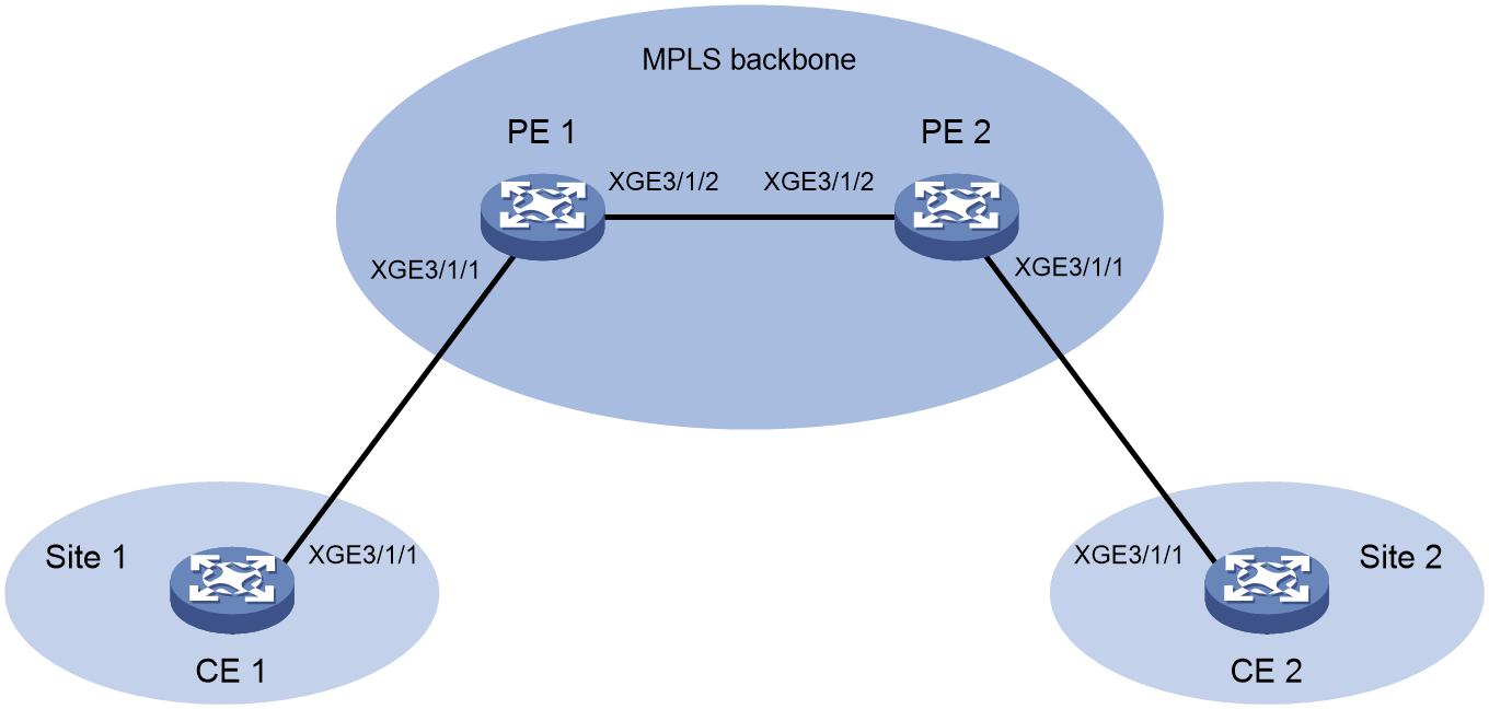
Procedure
1. Assign IP addresses to interfaces. (Details not shown.)
2. Configure static routes or a routing protocol and create an L2VPN to make sure the devices can reach each other. For more information about creating an L2VPN, see MPLS L2VPN in MPLS Configuration Guide.
3. Configure PE 1:
# Specify PE 1 as the TWAMP Light client.
<PE1> system-view
[PE1] nqa twamp-light client
# Specify a destination IP address (any valid IP address except the one on the connected interface of PE 2), destination MAC address (any valid MAC address), and destination port number (any valid port number) for the probe packets.
[PE1-nqa-twamp-light-client] test-session 1
[PE1-nqa-twamp-light-client-session1] destination ip 4.4.4.2
[PE1-nqa-twamp-light-client-session1] destination mac 0001-0001-0002
[PE1-nqa-twamp-light-client-session1] destination port 8888
# Specify Ten-GigabitEthernet3/1/1 as the source interface for the probe packets. Specify a source IP address (any valid IP address except the one on the connected interface of PE 1), source MAC address (any valid MAC address), and source port number (any valid port number) for the probe packets.
[PE1-nqa-twamp-light-client-session1] source interface gigabitethernet 1/0/1
[PE1-nqa-twamp-light-client-session1] source ip 4.4.4.1
[PE1-nqa-twamp-light-client-session1] source mac 0001-0001-0001
[PE1-nqa-twamp-light-client-session1] source port 7777
[PE1-nqa-twamp-light-client-session1] quit
[PE1-nqa-twamp-light-client] quit
4. Configure PE 2 as the TWAMP Light responder:
<PE2> system-view
# Enable the NQA server.
<DeviceB> system-view
[DeviceB] nqa server enable
# Create test session 1 on the TWAMP Light responder with the destination IP address 4.4.4.2, source IP address 4.4.4.1, destination port 8888, and source port 7777.
[PE2] nqa twamp-light responder
[PE2-nqa-twamp-light-responder] test-session 1 interface gigabitethernet 1/0/1 ip destination 4.4.4.2 source 4.4.4.1 destination-port 8888 source-port 7777 destination-mac 1-1-2 source-mac 1-1-1
[PE2-nqa-twamp-light-responder] quit
5. Start the TWAMP Light test on PE 1.
[PE1] nqa twamp-light sender
[PE1-nqa-twamp-light-sender] start test-session 1 permanent
Verifying the configuration
# Display information about test session 1.
[PE1] display nqa twamp-light client
Brief information about all test sessions:
Total sessions: 1
Active sessions: 1
-------------------------------------------------------------------
ID Status Source IP/Port Destination IP/Port
1 Active 4.4.4.1/7777 4.4.4.2/8888
# Display test session statistics about two-way packet loss for test session 1.
[PE1] display nqa twamp-light client statistics two-way-loss test-session 1
Latest two-way loss statistics:
Index Loss count Loss ratio Error count Error ratio
1 0 0.0000% 0 0.0000%
2 0 0.0000% 0 0.0000%
3 0 0.0000% 0 0.0000%
4 0 0.0000% 0 0.0000%
--------------------------------------------------------------------
Average loss count : 0 Average loss ratio : 0.0000%
Maximum loss count : 0 Maximum loss ratio : 0.0000%
Minimum loss count : 0 Minimum loss ratio : 0.0000%
Average error count: 0 Average error ratio: 0.0000%
Maximum error count: 0 Maximum error ratio: 0.0000%
Minimum error count: 0 Minimum error ratio: 0.0000%
# Display test session statistics about two-way delay for test session 1.
[PE1] display nqa twamp-light client statistics two-way-delay test-session 1
Latest two-way delay statistics(us):
Index Delay(Avg) Jitter(Avg) SD-jitter(Avg) DS-jitter(Avg)
1 46 1 2 1
2 46 1 2 1
3 46 0 1 1
4 46 0 1 1
--------------------------------------------------------------------
Average delay : 46 Average jitter : 1
Maximum delay : 46 Maximum jitter : 1
Minimum delay : 46 Minimum jitter : 0
Average SD jitter: 1 Average DS jitter: 1
Maximum SD jitter: 1 Maximum DS jitter: 1
Minimum SD jitter: 0 Minimum DS jitter: 0
Example: Configuring TWAMP Light test on an L3VPN network
Network configuration
As shown in Figure 45, create an L3VPN between PE 1 and PE 2 over the backbone to allow communication between CE 1 and CE 2. Configure a TWAMP Light test to measure the service quality from PE 1 to PE 2.
Figure 47 Network diagram
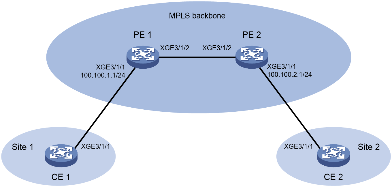
Procedure
1. Assign IP addresses to interfaces. (Details not shown.)
2. Configure static routes or a routing protocol and create an L3VPN to make sure the devices can reach each other. For more information about creating an L3VPN, see MPLS L3VPN in MPLS Configuration Guide.
3. Configure PE 1:
# Specify PE 1 as the TWAMP Light client.
<PE1> system-view
[PE1] nqa twamp-light client
# Specify 100.100.2.1 as the destination IP address and 10000 as the destination port number (use any valid port number) for the probe packets.
[PE1-nqa-twamp-light-client] test-session 1
[PE1-nqa-twamp-light-client-session1] destination ip 100.100.2.1
[PE1-nqa-twamp-light-client-session1] destination port 10000
# Specify 100.100.1.1 as the source IP address and 20000 as the source port number for the probe packets. Specify VPN instance 1 as the VPN instance where the test is performed
[PE1-nqa-twamp-light-client-session1] source ip 100.100.1.1
[PE1-nqa-twamp-light-client-session1] source port 20000
[PE1-nqa-twamp-light-client-session1] vpn-instance 1
[PE1-nqa-twamp-light-client-session1] quit
[PE1-nqa-twamp-light-client] quit
4. Configure PE 2 as the TWAMP Light responder:
# Enable the NQA server.
<DeviceB> system-view
[DeviceB] nqa server enable
# Create test session 1 on the TWAMP Light responder with the destination IP address 100.100.2.1, source IP address 100.100.1.1, destination port 10000, and source port 20000.
<PE2> system-view
[PE2] nqa twamp-light responder
[PE2-nqa-twamp-light-responder] test-session 1 ip destination 100.100.2.1 source 100.100.1.1 destination-port 10000 source-port 20000 vpn-instance 1
[PE2-nqa-twamp-light-responder] quit
5. Start the TWAMP Light test on PE 1.
[PE1] nqa twamp-light sender
[PE1-nqa-twamp-light-sender] start test-session 1 permanent
Verifying the configuration
# Display information about test session 1.
[PE1] display nqa twamp-light client
Brief information about all test sessions:
Total sessions: 1
Active sessions: 1
----------------------------------------------------------------------
ID Status Source IP/Port Destination IP/Port
1 Active 100.100.1.1/20000 100.100.2.1/10000
# Display test session statistics about two-way packet loss for test session 1.
[PE1] display nqa twamp-light client statistics two-way-loss test-session 1
Latest two-way loss statistics:
Index Loss count Loss ratio Error count Error ratio
1 0 0.0000% 0 0.0000%
2 0 0.0000% 0 0.0000%
3 0 0.0000% 0 0.0000%
4 0 0.0000% 0 0.0000%
--------------------------------------------------------------------
Average loss count : 0 Average loss ratio : 0.0000%
Maximum loss count : 0 Maximum loss ratio : 0.0000%
Minimum loss count : 0 Minimum loss ratio : 0.0000%
Average error count: 0 Average error ratio: 0.0000%
Maximum error count: 0 Maximum error ratio: 0.0000%
Minimum error count: 0 Minimum error ratio: 0.0000%
# Display test session statistics about two-way delay for test session 1.
[PE1] display nqa twamp-light client statistics two-way-delay test-session 1
Latest two-way delay statistics(us):
Index Delay(Avg) Jitter(Avg) SD-jitter(Avg) DS-jitter(Avg)
1 46 1 2 1
2 46 1 2 1
3 46 0 1 1
4 46 0 1 1
--------------------------------------------------------------------
Average delay : 46 Average jitter : 1
Maximum delay : 46 Maximum jitter : 1
Minimum delay : 46 Minimum jitter : 0
Average SD jitter: 1 Average DS jitter: 1
Maximum SD jitter: 1 Maximum DS jitter: 1
Minimum SD jitter: 0 Minimum DS jitter: 0
