- Table of Contents
-
- 15-Network Management and Monitoring Configuration Guide
- 00-Preface
- 01-System maintenance and debugging configuration
- 02-NQA configuration
- 03-iNQA configuration
- 04-iFIT configuration
- 05-SRPM configuration
- 06-NTP configuration
- 07-PTP configuration
- 08-Network synchronization configuration
- 09-SNMP configuration
- 10-RMON configuration
- 11-NETCONF configuration
- 12-CWMP configuration
- 13-EAA configuration
- 14-Process monitoring and maintenance configuration
- 15-Sampler configuration
- 16-Mirroring configuration
- 17-NetStream configuration
- 18-IPv6 NetStream configuration
- 19-TCP connection trace configuration
- 20-Performance management configuration
- 21-Fast log output configuration
- 22-Flow log configuration
- 23-Information center configuration
- 24-Packet capture configuration
- 25-Flow monitor configuration
- Related Documents
-
| Title | Size | Download |
|---|---|---|
| 05-SRPM configuration | 129.84 KB |
Restrictions and guidelines: SRPM configuration
Configuring a link-based delay profile
Creating a link-based delay profile
Specifying an encapsulation method for SRPM packets
Specifying UDP port numbers for SRPM packets
Setting the sending interval of SRPM query packets
Specifying a DSCP value for SRPM query packets
Activating a link-based delay profile
Specifying a destination IP address for SRPM packets
Display and maintenance commands for SRPM
Example: Configuring link-based SRPM delay measurement
Configuring SRPM
About SRPM
Segment Routing Performance Measurement (SRPM) is a technology used to dynamically measure the link performance, for example, link delay and jitter, in a segment routing (SR) network.
SRPM is applicable to SRv6 and SR-MPLS. For more information about SRv6 and SR-MPLS, see Segment Routing Configuration Guide.
Basic concepts
SRPM packets
SRPM supports SRPM query packets and SRPM response packets.
SRPM packets support UDP, UDPv6, and MPLS encapsulation.
When MPLS encapsulation is used, the destination MAC address of SRPM packets is multicast MAC address 0100-5e80-000d.
Measurement profiles
A measurement profile is a collection of measurement parameters. To configure different measurement schemes, you can define different measurement profiles.
In the current software version, only profiles for delay measurement (DM) are supported. The profiles are called delay profiles.
A link-based delay profile is used to measure delay on links. In the current software version, only point-to-point links support SRPM delay measurement.
Working mechanism
As shown in Figure 1, SRPM has the following roles:
· Local end—Responsible for starting SRPM measurement, periodically sending SRPM query packets to the remote end, and calculating the measurement result.
· Remote end—Responsible for replying to the SRPM query packets with SRPM response packets.
Figure 1 Two-way SRPM delay measurement
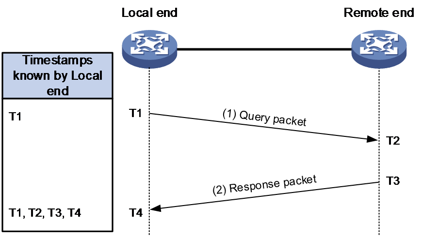
SRPM uses the following process to implement two-way delay measurement:
1. The local end sends an SRPM query packet to the remote end. The query packet contains timestamp T1 (time when the query packet was sent).
2. When the remote end receives the query packet, it records the receiving time as T2. Then, the remote end replies to the local end with an SRPM response packet at time T3. The response packet contains timestamp T1, T2, and T3.
3. When the local end receives the response packet, it records the receiving time as T4. Then, the local end uses the following formula to calculate the two-way delay: two-way delay = (T2 - T1) + (T4 - T3).
|
|
IMPORTANT: The local end can calculate jitter values after it obtains two or more two-way delay values. A jitter value is the absolute value for the difference between the delay values measured in two consecutive rounds. |
Protocols and standards
· RFC 6374, Packet Loss and Delay Measurement for MPLS Networks
· RFC 7213, MPLS Transport Profile (MPLS-TP) Next-Hop Ethernet Addressing
· RFC 7876, UDP Return Path for Packet Loss and Delay Measurement for MPLS Networks
Restrictions and guidelines: SRPM configuration
SRPM is supported only on the following Layer 3 interfaces:
· Layer 3 Ethernet interfaces.
· Layer 3 Ethernet subinterfaces.
· Layer 3 aggregate interfaces.
· Layer 3 aggregate subinterfaces.
· FlexE logical interfaces.
In standard system operating mode, only the following cards support this feature:
CSPEX-1802X, CSPEX-1802XA, CSPEX-1812X-E, CSPEX-2304X-G, CEPC-CQ8L, CEPC-CQ8LA, CEPC-CQ16L1, CSPEX-1502XA, RX-SPE200-E
In SDN-WAN system operating mode, only the following cards support this feature:
CSPEX-1304X, CSPEX-1404X, CSPEX-1502X, CSPEX-1504X, CSPEX-1504XA, CSPEX-1602X, CSPEX-1602XA, CSPEX-1804X, CSPEX-1512X, CSPEX-1612X, CSPEX-1812X, RX-SPE200, CEPC-XP4LX, CEPC-XP24LX, CEPC-XP48RX, CEPC-CP4RX, CEPC-CP4RXA, CEPC-CP4RX-L, CSPEX-1802X, CSPEX-1802XA, CSPEX-1812X-E, CSPEX-2304X-G, CEPC-CQ8L, CEPC-CQ8LA, CEPC-CQ16L1, CSPEX-1502XA, RX-SPE200-E
SRPM tasks at a glance
Configuring the local end
To configure SRPM on the local end, perform the following tasks:
1. Configuring a link-based delay profile
a. Creating a link-based delay profile
b. Specifying an encapsulation method for SRPM packets
c. (Optional. Specifying UDP port numbers for SRPM packets
This task is applicable to UDP or UDPv6 encapsulation.
d. (Optional.) Setting the sending interval of SRPM query packets
e. (Optional.) Specifying a DSCP value for SRPM query packets
f. Activating a link-based delay profile
2. Enabling SRPM on an interface
a. Specifying a destination IP address for SRPM packets
This task is required if UDP or UDPv6 encapsulation is used for SRPM packets.
Configuring the remote end
To configure SRPM on the remote end, perform the following tasks:
1. Configuring a link-based delay profile
a. Creating a link-based delay profile
b. Specifying an encapsulation method for SRPM packets
c. (Optional.) Specifying UDP port numbers for SRPM packets
This task is applicable to UDP or UDPv6 encapsulation.
d. Activating a link-based delay profile
Configuring a link-based delay profile
Creating a link-based delay profile
1. Enter system view.
system-view
2. Enable SRPM and enter SRPM view.
srpm
By default, SRPM is disabled.
3. Create a link-based delay profile and enter link-based delay profile view.
delay-profile link-based profile-name
Specifying an encapsulation method for SRPM packets
About this task
SRPM packets support the following encapsulation methods:
· MPLS encapsulation—MPLS is used to encapsulate SRPM packets.
· UDP encapsulation—UDP is used to encapsulate SRPM packets. The source and destination IP addresses in the IP header are IPv4 addresses.
· UDPv6 encapsulation—UDP is used to encapsulate SRPM packets. The source and destination IP addresses in the IP header are IPv6 addresses.
Restrictions and guidelines
As a best practice, set the encapsulation method to MPLS in an SR-MPLS network and set the encapsulation method to UDPv6 in an SRv6 network.
Procedure
1. Enter system view.
system-view
2. Enter SRPM view.
srpm
3. Enter link-based delay profile view.
delay-profile link-based profile-name
4. Specify an encapsulation method for SRPM packets.
protocol { mpls | udp | udpv6 }
By default, UDP encapsulation is used for SRPM packets.
Specifying UDP port numbers for SRPM packets
About this task
Perform this task to modify the source and destination port numbers of SRPM packets to avoid port number conflicts.
To obtain usage information about UDP port numbers, use the display udp command.
Restrictions and guidelines
The source port number and destination port number on the local end must be the same as the destination port number and source port number on the remote end, respectively.
Procedure
1. Enter system view.
system-view
2. Enter SRPM view.
srpm
3. Enter link-based delay profile view.
delay-profile link-based profile-name
4. Specify a source UDP port number for SRPM packets.
udp source-port port-number
By default, the source UDP port number of SRPM delay packets is 5245.
5. Specify a destination UDP port number for SRPM packets.
udp destination-port port-number
By default, the destination UDP port number of SRPM delay measurement packets is 5245.
Setting the sending interval of SRPM query packets
1. Enter system view.
system-view
2. Enter SRPM view.
srpm
3. Enter link-based delay profile view.
delay-profile link-based profile-name
4. Set the sending interval of SRPM query packets
interval interval-value
By default, SRPM query packets are sent at intervals of 30 seconds.
Specifying a DSCP value for SRPM query packets
About this task
DSCP determines packet transmission priority. The higher the DSCP value, the higher the transmission priority.
Procedure
1. Enter system view.
system-view
2. Enter SRPM view.
srpm
3. Enter link-based delay profile view.
delay-profile link-based profile-name
4. Specify a DSCP value for SRPM query packets.
dscp dscp-value
By default, the DSCP value is 0 for SRPM query packets.
Activating a link-based delay profile
About this task
After creating or modifying a delay profile, you must activate the profile for the new configuration to take effect.
Reactivating a delay profile clears history measurement statistics on SRPM-enabled interfaces that are associated with this delay profile. The interfaces will use the new configuration to start new measurement sessions.
Before modifying parameters in a delay profile or terminating measurement sessions related to that profile, you must use the undo activate profile command to deactivate that profile.
Procedure
1. Enter system view.
system-view
2. Enter SRPM view.
srpm
3. Enter link-based delay profile view.
delay-profile link-based profile-name
4. Activate the profile.
activate profile
By default, a link-based delay profile is not activated.
Enabling SRPM on an interface
Specifying a destination IP address for SRPM packets
Restrictions and guidelines
Perform this task on an interface of the local end to specify the IP address of an interface on the remote end as the destination IP address of SRPM packets.
Procedure
1. Enter system view.
system-view
2. Enter Layer 3 interface view.
interface interface-type interface-number
3. Specify a destination IP address for SRPM packets.
srpm destination { ipv4 ipv4-address | ipv6 ipv6-address }
By default, no destination IP address is specified for SRPM packets.
Enabling SRPM query
About this task
Perform this task on an interface of the local end to enable the interface to send SRPM delay measurement query packets.
Restrictions and guidelines
An interface can be associated only with one delay profile. To change the delay profile associated with an interface, you must first use the undo srpm delay-profile link-based query enable command to disable this feature.
Prerequisites
Create the delay profile that will be specified in the srpm delay-profile link-based query enable command and activate the profile by using the activate profile command. This configuration ensures that this feature can take effect.
Procedure
1. Enter system view.
system-view
2. Enable Layer 3 interface view.
interface interface-type interface-number
3. Enable link-based SRPM delay measurement query on the interface and associate a delay profile with the interface.
srpm delay-profile link-based profile-name query enable
By default, link-based SRPM delay measurement query is disabled on an interface.
Enabling SRPM response
About this task
Perform this task on an interface of the remote end to enable the interface to reply to the local end with SRPM delay measurement response packets.
Restrictions and guidelines
An interface can be associated only with one delay profile. To change the delay profile associated with an interface, you must first use the undo srpm delay-profile link-based response enable command to disable this feature.
Prerequisites
Create the delay profile that will be specified in the srpm delay-profile link-based response enable command and activate the profile by using the activate profile command. This configuration ensures that this feature can take effect.
Procedure
1. Enter system view.
system-view
2. Enable Layer 3 interface view.
interface interface-type interface-number
3. Enable link-based SRPM delay measurement response on the interface and associate a delay profile with the interface.
srpm delay-profile link-based profile-name response enable
By default, link-based SRPM delay measurement response is disabled on an interface.
Display and maintenance commands for SRPM
Execute display commands in any view and reset commands in user view.
|
Task |
Command |
|
Display information about SRPM link-based delay profiles. |
display srpm delay-profile { brief | link-based [ profile-name ] } |
|
Display statistics about SRPM delay measurement. |
display srpm delay-statistics [ interface interface-type interface-number ] [ number number ] |
|
Display interface-specific SRPM information. |
display srpm interface interface-type interface-number display srpm interface [ interface-type interface-number ] brief |
|
Clear statistics about SRPM delay measurement. |
reset srpm delay-statistics interface interface-type interface-number |
SRPM configuration examples
Example: Configuring link-based SRPM delay measurement
Network configuration
As shown in Figure 2, the devices are in an SRv6 network. Use SRPM to measure two-way delay for the links between Device A and Device B and between Device B and Device C. Device B is the remote end to Device A and Device C is the remote end to Device B.

Restrictions and guidelines
The delay measurement configuration is the same in an SRv6 network and an SR-MPLS network except for the following settings:
· In an SRv6 network, you must use the srpm destination command to specify a destination IP address for SRPM packets. This configuration is not required in an SR-MPLS network.
· In an SRv6 network, set the encapsulation method to UDPv6 for SRPM packets. In an SR-MPLS network, set the encapsulation method to MPLS for SRPM packets.
Prerequisites
1. Assign IP addresses to interfaces.
2. Configure static routing or dynamic routing to make sure the devices can reach each other.
Procedure
1. Configure Device A:
# Enable SRPM and enter SRPM view.
<DeviceA> system-view
[DeviceA] srpm
# Create a link-based delay profile named test1, set the encapsulation method to UDPv6 for SRPM packets, and activate the profile.
[DeviceA-srpm] delay-profile link-based test1
[DeviceA-srpm-delay-profile-link-based-test1] protocol udpv6
[DeviceA-srpm-delay-profile-link-based-test1] activate profile
[DeviceA-srpm-delay-profile-link-based-test1] quit
[DeviceA-srpm] quit
# On interface Ten-GigabitEthernet 3/1/1, specify the IP address of Ten-GigabitEthernet 3/1/2 on Device B as the destination IP address of SRPM packets.
[DeviceA] interface ten-gigabitethernet 3/1/1
[DeviceA-Ten-GigabitEthernet3/1/1] srpm destination ipv6 1::2
# Enable link-based SRPM delay measurement query and associate delay profile test1 with the interface.
[DeviceA-Ten-GigabitEthernet3/1/1] srpm delay-profile link-based test1 query enable
[DeviceA-Ten-GigabitEthernet3/1/1] quit
2. Configure Device B:
# Enable SRPM and enter SRPM view.
<DeviceB> system-view
[DeviceB] srpm
# Create a link-based delay profile named test1, set the encapsulation method to UDPv6 for SRPM packets, and activate the profile.
[DeviceB-srpm] delay-profile link-based test1
[DeviceB-srpm-delay-profile-link-based-test1] protocol udpv6
[DeviceB-srpm-delay-profile-link-based-test1] activate profile
[DeviceB-srpm-delay-profile-link-based-test1] quit
[DeviceB-srpm] quit
# On interface Ten-GigabitEthernet 3/1/2, enable link-based SRPM delay measurement response and associate the interface with profile test1.
[DeviceB] interface ten-gigabitethernet 3/1/2
[DeviceB-Ten-GigabitEthernet3/1/2] srpm delay-profile link-based test1 response enable
[DeviceB-Ten-GigabitEthernet3/1/2] quit
# On interface Ten-GigabitEthernet 3/1/1, specify the IP address of Ten-GigabitEthernet 3/1/2 on Device C as the destination IP address of SRPM packets.
[DeviceB] interface ten-gigabitethernet 3/1/1
[DeviceB-Ten-GigabitEthernet3/1/1] srpm destination ipv6 2::2
# Enable link-based SRPM delay measurement query and associate delay profile test1 with the interface.
[DeviceB-Ten-GigabitEthernet3/1/1] srpm delay-profile link-based test1 query enable
[DeviceB-Ten-GigabitEthernet3/1/1] quit
3. Configure Device C:
# Enable SRPM and enter SRPM view.
<DeviceC> system-view
[DeviceC] srpm
# Create a link-based delay profile named test1, set the encapsulation method to UDPv6 for SRPM packets, and activate the profile.
[DeviceC-srpm] delay-profile link-based test1
[DeviceC-srpm-delay-profile-link-based-test1] protocol udpv6
[DeviceC-srpm-delay-profile-link-based-test1] activate profile
[DeviceC-srpm-delay-profile-link-based-test1] quit
[DeviceC-srpm] quit
# On interface Ten-GigabitEthernet 3/1/2, enable link-based SRPM delay measurement response and associate delay profile test1 with the interface.
[DeviceC] interface ten-gigabitethernet 3/1/2
[DeviceC-Ten-GigabitEthernet3/1/2] srpm delay-profile link-based test1 response enable
[DeviceC-Ten-GigabitEthernet3/1/2] quit
Verifying the configuration
1. Display two-way delay between Device A and Device B.
On Device A, display the most recent five SRPM delay measurement statistics on interface Ten-GigabitEthernet 3/1/1.
[DeviceA] display srpm delay-statistics interface ten-gigabitethernet 3/1/1
Latest two-way delay statistics (us) for Ten-GigabitEthernet3/1/1:
Index Delay Jitter
11 9 -
12 7 2
13 11 4
14 10 1
15 8 2
Average delay: 9 Average jitter: 2
Maximum delay: 11 Maximum jitter: 4
Minimum delay: 7 Minimum jitter: 1
2. Display two-way delay between Device B and Device C.
On Device B, display the most recent five SRPM delay measurement statistics on interface Ten-GigabitEthernet 3/1/1.
[DeviceB] display srpm delay-statistics interface ten-gigabitethernet 3/1/1
...
