- Table of Contents
-
- 04-Layer 2—LAN Switching Configuration Guide
- 00-Preface
- 01-MAC address table configuration
- 02-Ethernet link aggregation configuration
- 03-Port isolation configuration
- 04-VLAN configuration
- 05-QinQ configuration
- 06-VLAN termination configuration
- 07-Loop detection configuration
- 08-Spanning tree configuration
- 09-LLDP configuration
- 10-Layer 2 forwarding configuration
- Related Documents
-
| Title | Size | Download |
|---|---|---|
| 03-Port isolation configuration | 75.11 KB |
Contents
Assigning a port to the isolation group
Display and maintenance commands for port isolation
Port isolation configuration examples
Example: Configuring port isolation
Example: Configuring port isolation (for single-isolation group devices)
Configuring port isolation
About port isolation
The port isolation feature isolates Layer 2 traffic for data privacy and security without using VLANs.
Ports in an isolation group cannot communicate with each other. However, they can communicate with ports outside the isolation group.
Assigning a port to the isolation group
About this task
The device supports only one isolation group that is automatically created as isolation group 1. You cannot remove the isolation group or create other isolation groups on the device. The number of ports assigned to the isolation group is not limited.
Restrictions and guidelines
· The configuration in Layer 2 Ethernet interface view applies only to the interface.
· The configuration in Layer 2 aggregate interface view applies to the Layer 2 aggregate interface and its aggregation member ports. If the device fails to apply the configuration to the aggregate interface, it does not assign any aggregation member port to the isolation group. If the failure occurs on an aggregation member port, the device skips the port and continues to assign other aggregation member ports to the isolation group.
Procedure
1. Enter system view.
system-view
2. Enter interface view.
¡ Enter Layer 2 Ethernet interface view.
interface interface-type interface-number
¡ Enter Layer 2 aggregate interface view.
interface bridge-aggregation interface-number
3. Assign the port to the isolation group.
port-isolate enable
By default, the port is not in the isolation group.
Display and maintenance commands for port isolation
Execute display commands in any view.
|
Task |
Command |
|
Display port isolation group information. |
display port-isolate group |
Port isolation configuration examples
Example: Configuring port isolation
Network configuration
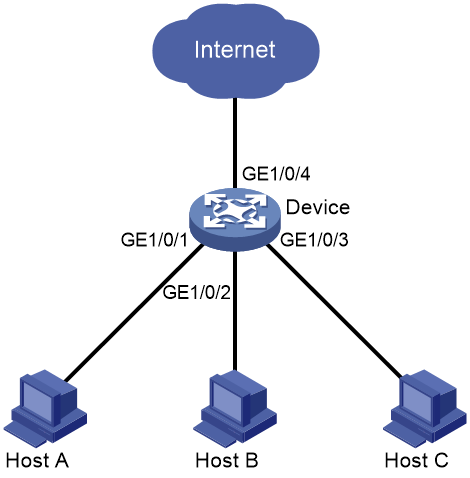
As shown in Figure 1:
· LAN users Host A, Host B, and Host C are connected to GigabitEthernet 2/0/1, GigabitEthernet 2/0/2, and GigabitEthernet 2/0/3 on the device, respectively.
· The device connects to the Internet through GigabitEthernet 2/0/4.
Configure the device to provide Internet access for all the hosts, and isolate them from one another.
Procedure
# Assign GigabitEthernet2/0/1, GigabitEthernet2/0/2, and GigabitEthernet2/0/3 to the isolation group.
<Device> system-view
[Device] interface gigabitethernet 2/0/1
[Device-GigabitEthernet2/0/1] port-isolate enable
[Device-GigabitEthernet2/0/1] quit
[Device] interface gigabitethernet 2/0/2
[Device-GigabitEthernet2/0/2] port-isolate enable
[Device-GigabitEthernet2/0/2] quit
[Device] interface gigabitethernet 2/0/3
[Device-GigabitEthernet2/0/3] port-isolate enable
[Device-GigabitEthernet2/0/3] quit
Verifying the configuration
# Display information about the isolation group.
[Device] display port-isolate group
Port isolation group information:
Group ID: 1
Group members:
GigabitEthernet2/0/1 GigabitEthernet2/0/2 GigabitEthernet2/0/3
Community VLAN ID: None
The output shows that GigabitEthernet 2/0/1, GigabitEthernet 2/0/2, and GigabitEthernet 2/0/3 are assigned to the isolation group. As a result, Host A, Host B, and Host C are isolated from one another at Layer 2.
Example: Configuring port isolation (for single-isolation group devices)
This example applies to devices that support only one isolation group.
Network requirements
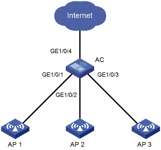
As shown in Figure 2, AP 1, AP 2, and AP 3 are connected to GigabitEthernet 1/0/1, GigabitEthernet 1/0/2, and GigabitEthernet 1/0/3 on the AC, respectively. The AC connects to the Internet through GigabitEthernet 1/0/4.
Configure the AC to provide Internet access for the APs, and isolate APs from one another.
Configuration procedure
# Assign ports GigabitEthernet 1/0/1, GigabitEthernet 1/0/2, and GigabitEthernet 1/0/3 to the isolation group.
<AC> system-view
[AC] interface gigabitethernet 1/0/1
[AC-GigabitEthernet1/0/1] port-isolate enable
[AC-GigabitEthernet1/0/1] quit
[AC] interface gigabitethernet 1/0/2
[AC-GigabitEthernet1/0/2] port-isolate enable
[AC-GigabitEthernet1/0/2] quit
[AC] interface gigabitethernet 1/0/3
[AC-GigabitEthernet1/0/3] port-isolate enable
[AC-GigabitEthernet1/0/3] quit
Verifying the configuration
# Display information about the isolation group.
[AC] display port-isolate group
Port isolation group information:
Group ID: 1
Group members:
GigabitEthernet1/0/1 GigabitEthernet1/0/2 GigabitEthernet1/0/3
The output shows that ports GigabitEthernet 1/0/1, GigabitEthernet 1/0/2, and GigabitEthernet 1/0/3 are assigned to the isolation group. As a result, the APs are isolated from one another at Layer 2.
