- Table of Contents
- Related Documents
-
| Title | Size | Download |
|---|---|---|
| 02-Installing the router | 2.19 MB |
Contents
Mounting the router on a workbench
Installing the router in a rack
Attaching the ring terminal to the grounding cable
Grounding the router with a grounding strip
Grounding the router through the rack
Connecting the console cable and setting terminal parameters
Accessing the router for the first time
Installing the router
|
WARNING! To avoid injury, do not touch bare wires, terminals, or parts with high-voltage hazard signs. |
|
|
IMPORTANT: · The barcode on the router chassis contains product information that must be provided to local sales agent when you return a faulty router for service. · Keep the tamper-proof seal on a mounting screw on the chassis cover intact, and if you want to open the chassis, contact H3C for permission. Otherwise, H3C shall not be liable for any consequence. |
Installation prerequisites
· You have read "Preparing for installation" carefully.
· All requirements in "Preparing for installation" are met.
Installation flow
You can install the router on a workbench or in a rack. Select an installation method according to the installation environment, and follow the installation flowchart shown in Figure 1.

Installing the router
Mounting the router on a workbench
|
|
IMPORTANT: · Ensure good ventilation and 100 mm (3.94 in) of clearance around the chassis for heat dissipation. · Do not place heavy objects on the router. |
To mount the router on a workbench:
1. Make sure the workbench is clean, stable, and correctly grounded.
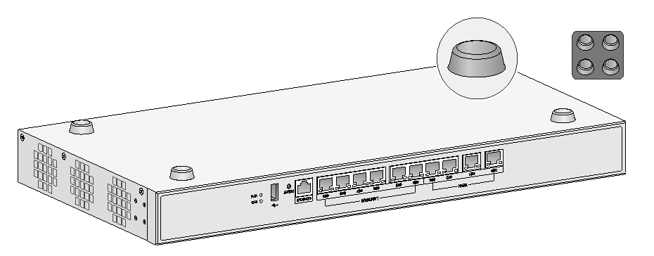
2. Place the router upside down on the workbench and attach the rubber feet to the four round holes in the chassis bottom.
Figure 2 Attaching the rubber feet
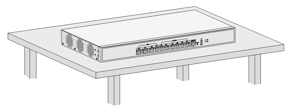
3. Place the router on the workbench with the upside up.
Figure 3 Mounting the router on a workbench
Installing the router in a rack
|
|
WARNING! The mounting brackets can only support the weight of the router. To avoid damage to the router, do not place any objects on the router. |
To install the router in a rack:
1. Use a mounting bracket to mark the positions of cage nuts on the front rack posts. Make sure the cage nut installation holes on the front rack posts are on a horizontal line.
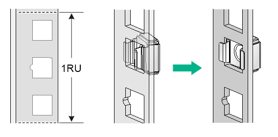
2. Install cage nuts, as shown in Figure 4.
a. Insert one ear of a cage nut into the marked installation hole.
b. Use a flathead screwdriver to push the other ear into the same hole.
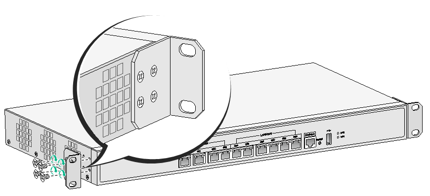
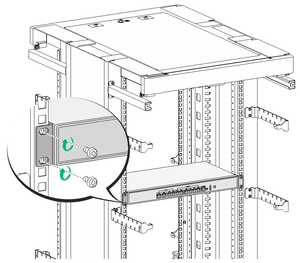
3. Attach mounting brackets to both sides of the router, as shown in Figure 5.
Figure 5 Attaching the mounting bracket to the router
4. Use M6 screws to attach the mounting brackets on the router to the front rack posts, as shown in Figure 6.
Figure 6 Securing the router to the rack
Grounding the router
|
|
WARNING! Correctly connecting the router grounding cable is crucial to lightning protection and EMI protection. |
|
|
IMPORTANT: The resistance reading must be smaller than 5 ohms between the chassis and the ground. |
Attaching the ring terminal to the grounding cable
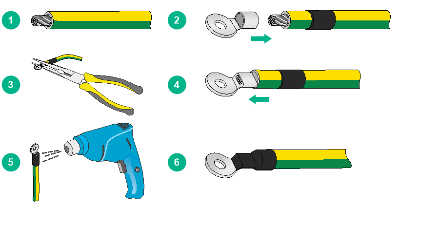
The router comes with a ring terminal. No grounding cable is provided with the router. Purchase a grounding cable yourself. Before grounding the router, attach the provided ring terminal to the grounding cable.
To attach the ring terminal to the grounding cable:
1. Cut the grounding cable to the desired length. Use the wire-stripping pliers to peel 5 mm (0.20 in) of insulation sheath from one end of the grounding cable.
2. Add a heat-shrink tubing onto the cable, and insert the bare metal part of the grounding cable into the ring terminal.
3. Use the needle-nose pliers to secure the metal part of the cable in the ring terminal.
4. Cover the joint with the heat-shrink tubing, and use a heat gun to shrink the tubing around the cable.
Figure 7 Attaching the ring terminal to the grounding cable
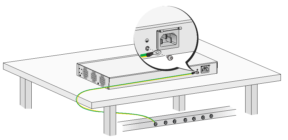
Grounding the router with a grounding strip
1. Remove the grounding screw from the grounding hole on the rear panel of the chassis.
2. Use the grounding screw to attach the ring terminal of the grounding cable to the grounding hole.
3. Use a screwdriver to fasten the grounding screw.
4. Remove the hex nut from a grounding post on the grounding strip.
5. Use the removed hex nut to attach the other end of the grounding cable to the grounding post.
Figure 8 Connecting the router with a grounding strip
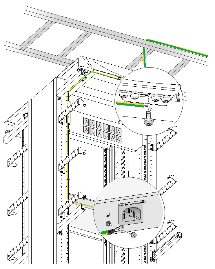
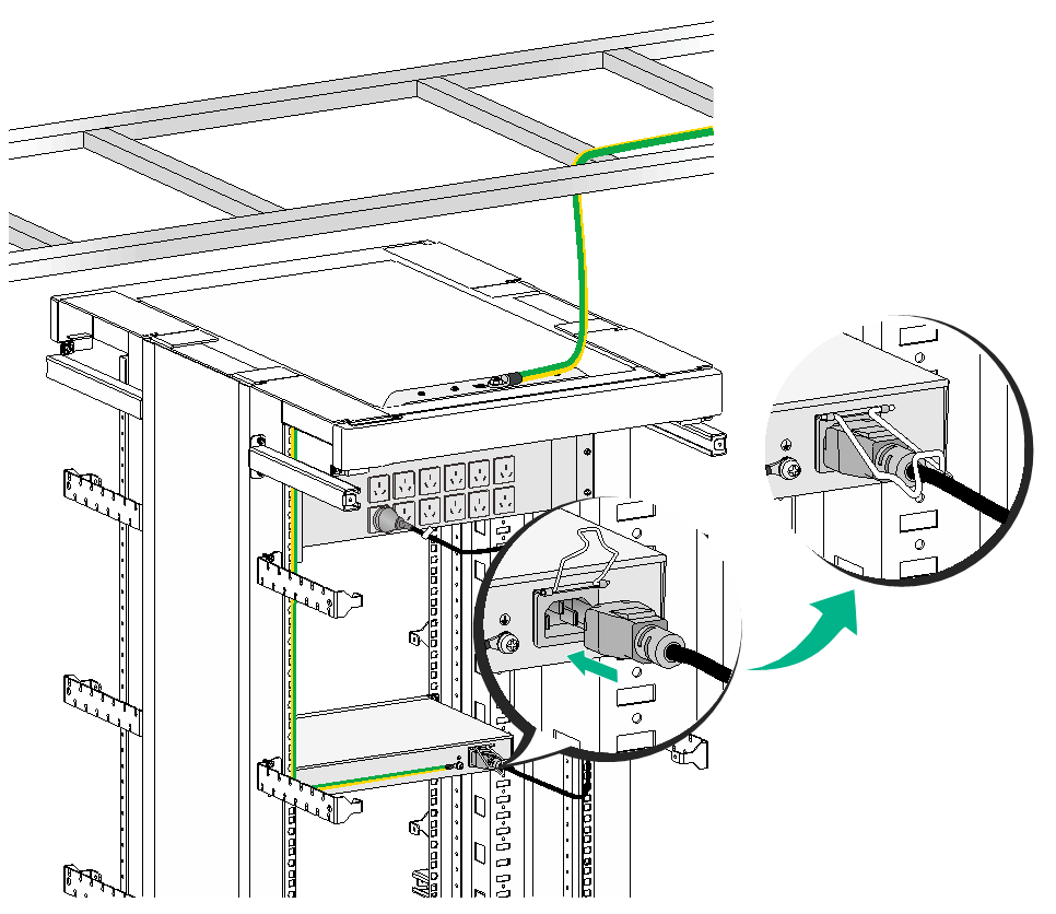
Grounding the router through the rack
|
|
IMPORTANT: Make sure the rack is correctly grounded before grounding the router through the rack. |
To connect the grounding cable through the rack:
1. Remove the grounding screw from the grounding hole on the rear panel of the chassis.
2. Use the grounding screw to attach the ring terminal of the grounding cable to the grounding hole.
3. Use a screwdriver to fasten the grounding screw.
4. Remove the nut from the grounding post of the grounding point on the rack.
5. Use the needle-nose pliers to bend a hook at the other end of the grounding cable, and use the removed nut to attach the hook to the grounding post.
Figure 9 Grounding the router through the rack
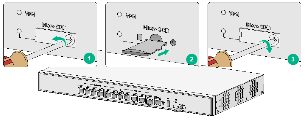
Installing a Micro SD card
|
|
CAUTION: To avoid damaging the Micro SD card slot, do not use excessive force when you install a Micro SD card. |
Only the MSR830-6HI-GL and MSR830-10HI-GL routers support Micro SD cards.
To install a Micro SD card:
1. Remove the screw on cover over the Micro SD card slot and remove the cover.
2. Insert the Micro SD card into the slot along the slide rails.
If you encounter any resistance, re-orient the card and try to insert it again.
3. Reinstall the cover and fasten the screw on the cover.
Figure 10 Installing a Micro SD card
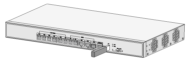
Connecting a USB drive
Connect a USB drive to the USB port of the router as shown in Figure 11.
Figure 11 Connecting a USB drive
Connecting interface cables
Connecting an AC power cord
1. Make sure the router is correctly grounded.
2. Attach the bail latch to the router.
3. Connect one end of the AC power cord to the AC receptacle on the router, and the other end to the AC power source.
4. Use the bail latch to secure the power cord.
Figure 12 Connecting an AC power cord
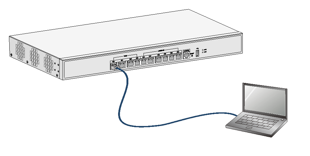
Connecting an Ethernet cable
1. Connect one end of the cable to an Ethernet port on the router and the other end to an Ethernet port on the peer device.
2. Examine the port LED on the router. For more information about the LEDs, see "LED description."
Figure 13 Connecting the Ethernet cable
Connecting an optical fiber
|
|
WARNING! Do not stare into any fiber port when you connect an optical fiber. The laser light emitted from the optical fiber might hurt your eyes. |
|
|
CAUTION: · To connect a fiber port by using an optical fiber, first install a transceiver module in the port and then connect the optical fiber to the transceiver module. · Install a dust cap on any open optical fiber connector and insert a dust plug into any open fiber port or transceiver module port to protect them from contamination and ESD damage. · Never bend an optical fiber excessively. The bend radius of an optical fiber must be not less than 100 mm (3.94 in). · Keep the fiber end clean. · Make sure the Tx and Rx ports on a transceiver module are connected to the Rx and Tx ports on the peer end, respectively. |
Only the MSR830-6HI-GL and MSR830-10HI-GL routers support transceiver modules.
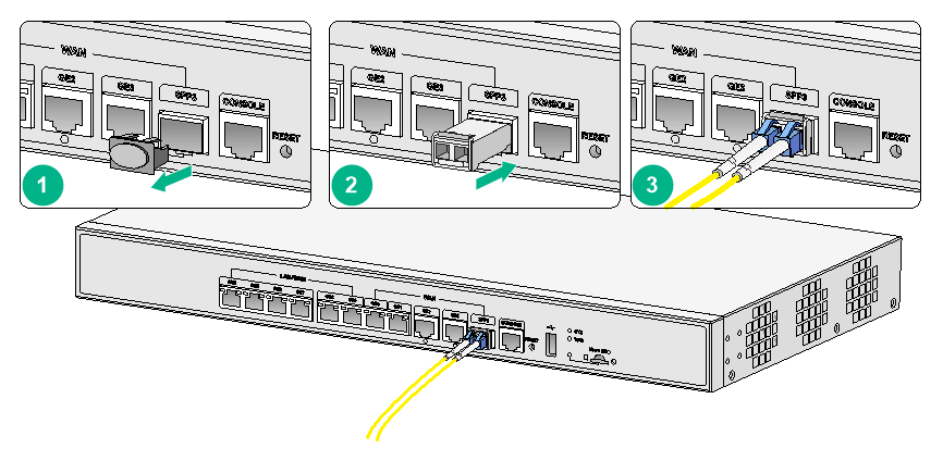
To connect an optical fiber:
1. Remove the dust plug from a fiber port of the router.
2. Remove the dust plug from the transceiver module, and plug the end without a pull latch into the fiber port.
3. Remove the dust cap from the fiber connector.
4. Identify the Rx and Tx ports. Plug the LC connector at one end of one fiber cable into the Rx port of the router and the LC connector at the other end into the Tx port of the peer device. Plug the LC connector at one end of another fiber cable into the Tx port of the router and the LC connector at the other end to the Rx port of the peer device.
5. Examine the fiber port LED. For more information, see "Appendix B LEDs."
Figure 14 Connecting an optical fiber
Connecting the console cable and setting terminal parameters
To access the router at the first time, you can only use a console cable to connect the console port on the router to a configuration terminal.
Connecting the console cable
|
|
IMPORTANT: · When you connect a PC to a powered-on router, first connect the DB-9 connector of the console cable to the PC, and then connect the RJ-45 connector to the router. · If the PC does not have a DB-9 port, prepare a DB-9-to-RJ-45 adapter. |
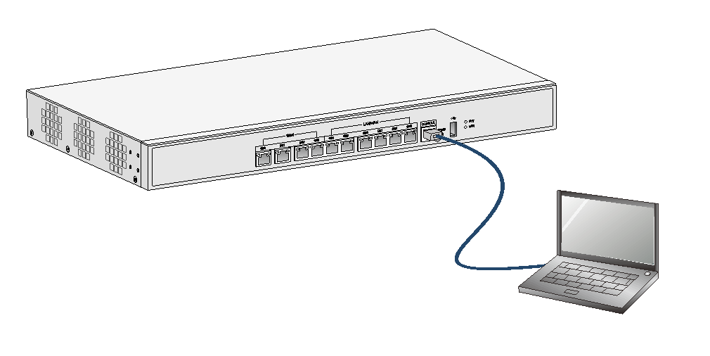
To connect the console cable:
1. Select a configuration terminal, which can be an ASCII terminal with an RS-232 serial port or a PC. (A PC is more commonly used.)
2. Connect the DB-9 connector (female) of the console cable to the RS-232 serial port on the configuration terminal and the RJ-45 connector to the console port of the router.
Figure 15 Connecting the console cable
Setting terminal parameters
To access the device through the console port, you must run a terminal emulator program (HyperTerminal, PuTTY, or Tera Term) on the configuration terminal. For information about using a terminal emulator program, see the program's user guide.
The following are the required terminal settings:
· Baud rate—9600.
· Data bits—8.
· Stop bits—1.
· Parity—none.
· Flow control—none.
Verifying the installation
After you complete the installation, verify the following information:
· There is enough space for heat dissipation around the router, and the rack or workbench is stable.
· The USB device, if any, is correctly installed.
· The router and the power source are correctly grounded.
· The correct power source is used.
· The router is connected correctly to the console terminal and other devices.
Accessing the router for the first time
|
WARNING! Before powering on the router, locate the switch for the power source so that you can cut off power promptly in case of an emergency. |
For a router starting with empty configuration, you must press Ctrl+D to access the CLI.
To access the router for the first time:
1. Verify that the installation and configuration environment is as described in "Verifying the installation."
2. Power on the router.
3. During the booting process, verify the following items:
¡ The system LED (SYS) on the front panel is flashing green at 1 Hz. For more information about LEDs, see "Appendix B LEDs."
¡ The configuration terminal displays information correctly.
The router first initializes its memory at startup and then runs BootWare.
System is starting...
Press Ctrl+D to access BASIC-BOOTWARE MENU
Booting Normal Extended BootWare
****************************************************************************
* *
* H3C MSR830 BootWare, Version 1.12 *
* *
****************************************************************************
Copyright (c) 2004-2017 New H3C Technologies Co., Ltd.
Compiled Date : Jun 20 2017
CPU ID : 0xc
CPU L1 Cache : 32KB
CPU L2 Cache : 1024KB
Memory Type : DDR3 SDRAM
Memory Size : 1024MB
Flash Size : 256MB
PCB Version : 1.0
BootWare Validating...
Press Ctrl+B to access EXTENDED-BOOTWARE MENU...
Loading the main image files...
Loading file flash:/msr830hi-cmw710-system-e0707p02.bin.....................
.........................................Done.
Loading file flash:/msr830hi-cmw710-security-e0707p02.bin....Done.
Loading file flash:/msr830hi-cmw710-voice-e0707p02.bin....Done.
Loading file flash:/msr830hi-cmw710-data-e0707p02.bin......Done.
Loading file flash:/msr830hi-cmw710-boot-e0707p02.bin.........Done.
Image file flash:/msr830hi-cmw710-boot-e0707p02.bin is self-decompressing...
............................................................................
............................................................................
............................................................................
............................................................................
............................................................................
............................................................................
............................................................................
.................Done.
System image is starting...
Cryptographic algorithms tests passed.
Line con0 is available.
Press ENTER to get started.
4. Press Enter. The router is ready to configure when you see the following prompt:
<H3C>
5. Configure basic settings for the router. For more information, see the relevant documents.
