- Table of Contents
- Related Documents
-
| Title | Size | Download |
|---|---|---|
| 01-Preparing for installation | 360.01 KB |
Preparing for installation
Figure 1 This document applies to the following device models:
|
Model |
Product code |
|
MSR830-6EI-GL |
RT-MSR830-6EI-GL |
|
MSR830-6HI-GL |
RT-MSR830-6HI-GL |
|
MSR830-10HI-GL |
RT-MSR830-10HI-GL |
|
MSR830-10EI-GL |
RT-MSR830-10EI-GL |
Safety recommendations
Safety symbols
When reading this document, note the following symbols:
![]() WARNING means an alert that calls attention to important information that if
not understood or followed can result in personal injury.
WARNING means an alert that calls attention to important information that if
not understood or followed can result in personal injury.
![]() CAUTION means an alert that calls attention to important information that if
not understood or followed can result in data loss, data corruption, or damage
to hardware or software.
CAUTION means an alert that calls attention to important information that if
not understood or followed can result in data loss, data corruption, or damage
to hardware or software.
General safety recommendations
· Keep the chassis and installation tools away from walk areas.
· Make sure the ground is dry and flat and anti-slip measures are in place.
· Unplug all the external cables (including power cords) before moving the chassis.
Electricity safety
· Locate the emergency power-off switch in the room before installation. Shut the power off at once in case accident occurs. Disconnect the power cord of the router if necessary.
· Make sure the router is correctly grounded.
· Do not open or close the chassis cover when the router is powered on.
· Correctly connect the interface cables of the router.
· Use an uninterrupted power supply (UPS).
· Do not work alone when the router has power.
· Always make sure the power has been disconnected during the installation and replacement procedures.
Examining the installation site
The router can only be used indoors. To make sure the router operates correctly and to prolong its service lifetime, the installation site must meet the following requirements.
Temperature and humidity
Maintain temperature and humidity in the equipment room at acceptable levels.
· Lasting high relative humidity tends to cause poor insulation, electricity leakage, mechanical property change of materials, and corrosion of metal parts.
· Lasting low relative humidity is likely to result in loose screws due to washer contraction, and even ESD, which causes the circuits to fail.
· A high temperature is the most undesirable condition, because it accelerates the aging of insulation materials and significantly lowers reliability and service life of the router.
For the temperature and humidity requirements of the router, see Table 1.
Table 1 Temperature and humidity requirements
|
Temperature |
Humidity |
|
0°C to 45°C (32°F to 113°F) |
5% to 90% (noncondensing) |
Cleanliness
Dust buildup on the chassis might result in electrostatic adsorption, which causes poor contact of metal components and contact points, especially when indoor relative humidity is low. In the worst case, electrostatic adsorption can cause communication failure.
Table 2 Dust concentration limit in the equipment room
|
Substance |
Concentration limit (particles/m3) |
|
Dust particles |
≤ 3 x 10⁴ (No visible dust on desk in three days) |
|
NOTE: Dust particle diameter ≥ 5 µm |
|
The equipment room must also meet limits on salts, acids, and sulfides to eliminate corrosion and premature aging of components, as shown in Table 3.
Table 3 Harmful gas limits in the equipment room
|
Gas |
Max. (mg/m3) |
|
SO2 |
0.2 |
|
H2S |
0.006 |
|
NH3 |
0.05 |
|
Cl2 |
0.01 |
|
NO2 |
0.04 |
|
Cl2 |
0.01 |
Cooling system
To ensure good ventilation, the following requirements must be met:
· The air inlet and outlet vents are not blocked, and leave at least 100 mm (3.94 in) of clearance.
· The installation site has a good cooling system.
ESD prevention
|
|
CAUTION: Check the resistance of the ESD wrist strap for safety. The resistance reading must be in the range of 1 to 10 megohm (Mohm) between human body and the ground. |
To prevent electrostatic discharge (ESD), follow these guidelines:
· Make sure the router and the floor are correctly grounded.
· Take dust-proof measures for the equipment room.
· Maintain the humidity and temperature at acceptable levels.
· Always wear an ESD wrist strap and ESD clothing when touching a circuit board or transceiver module.
The router does not supply an ESD wrist strap. Prepare an ESD wrist strap yourself.
To attach an ESD wrist strap:
1. Wear the wrist strap on your wrist.
2. Lock the wrist strap tight around your wrist to keep good contact with the skin.
3. Secure the wrist strap lock and the alligator clip lock together.
4. Attach the alligator clip to the rack grounding terminal.
5. Make sure the rack is correctly grounded.
EMI
Electromagnetic interference (EMI) might be coupled from the source to the router through the following coupling mechanisms:
· Capacitive coupling
· Inductive coupling
· Radiative coupling
· Common impedance coupling
· Conductive coupling
To prevent EMI, take the following actions:
· Take measures against interference from the power grid.
· Do not use the router together with the grounding equipment or lightning-prevention equipment of power equipment, and keep the router far away from them.
· Keep the router far away from high-power radio launchers, radars, and equipment with high frequency or high current.
· Use electromagnetic shielding when necessary.
Lightning protection
To better protect the router from lightning, do as follows:
· Make sure the grounding cable of the chassis is correctly grounded.
· Make sure the grounding terminal of the AC power receptacle is correctly grounded.
· Install a lightning arrester at the input end of the power supply to enhance the lightning protection capability of the power supply.
Rack-mounting
Before mounting the router in a standard 19-inch rack, adhere to the following requirements:
· The rack is equipped with a good ventilation system.
· The rack is sturdy enough to support the router and its accessories.
· For heat dissipation and device maintenance, make sure the front and rear of the rack are at least 0.8 m (2.62 ft) away from walls or other devices, and the headroom in the equipment room is no less than 3 m (9.84 ft).
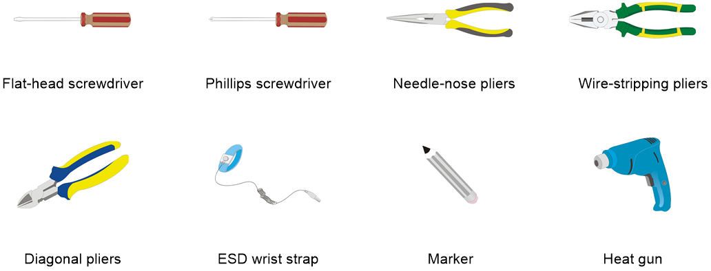
Installation tools
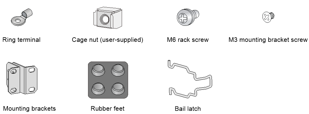
Installation accessories
Pre-installation checklist
Table 4 Pre-installation checklist
|
Item |
Requirements |
Result |
|
|
Installation site |
Ventilation |
· There is a minimum clearance of 100 mm (3.94 in) around the inlet and outlet vents for heat dissipation of the router chassis. · A good ventilation system is available at the installation site. |
|
|
Temperature |
0°C to 45°C (32°F to 113°F). |
|
|
|
Humidity |
5% RH to 90% RH (noncondensing). |
|
|
|
Cleanliness |
· Dust concentration ≤ 3 × 10⁴ particles/m3. · No visible dust on desk within three days. |
|
|
|
ESD prevention |
· The equipment and floor are correctly grounded. · The equipment room is dust-proof. · The humidity and temperature are at acceptable levels, respectively. · Wear an ESD wrist strap and uniform when touching a circuit board. |
|
|
|
EMI prevention |
· Take effective measures to protect the power system from the power grid system. · Separate the protection ground of the router from the grounding device or lightning protection grounding device as far as possible. · Keep the router far away from radio stations, radar and high-frequency devices working in high current. · Use electromagnetic shielding when necessary. |
|
|
|
Lightning protection |
· The grounding cable of the chassis is correctly grounded. · The grounding terminal of the AC power receptacle is correctly grounded. · A port lightning arrester is installed. (Optional.) · A power lightning arrester is installed. (Optional.) · A signal lightning arrester is installed at the input end of an external signal cable. (Optional.) |
|
|
|
Electricity safety |
· Equip an UPS. · The power-off switch in the equipment room is identified and accessible so that the power can be immediately shut off when an accident occurs. |
|
|
|
Workbench |
· The workbench is stable enough. · The workbench is correctly grounded. |
|
|
|
Safety precautions |
· The router is far away from any moist area and heat source. · The emergency power switch in the equipment room is located. |
|
|
|
Tools |
· Installation accessories supplied with the router. · User supplied tools. |
|
|
|
Reference |
· Documents shipped with the router. · Online documents. |
|
|
