- Table of Contents
-
- 04-Layer 3 Configuration Guide
- 00-Preface
- 01-Basic IP Routing Configuration
- 02-Static Routing Configuration
- 03-IPv6 Static Routing Configuration
- 04-IP Addressing Configuration
- 05-IPv6 Basics Configuration
- 06-DHCP Configuration
- 07-DHCPv6 Configuration
- 08-DNS Configuration
- 09-IPv6 DNS Configuration
- 10-IP Performance Optimization Configuration
- 11-ARP Configuration
- 12-IP Forwarding Basics Configuration
- 13-NAT Configuration
- Related Documents
-
| Title | Size | Download |
|---|---|---|
| 04-IP Addressing Configuration | 116.09 KB |
Assigning an IP address to an interface
IP address configuration example
Displaying and maintaining IP addressing
This chapter describes IP addressing basic and manual IP address assignment for interfaces. Dynamic IP address assignment (DHCP) and PPP address negotiation are beyond the scope of this chapter.
Overview
This section describes the IP addressing basics.
IP addressing uses a 32-bit address to identify each host on a network. To make addresses easier to read, they are written in dotted decimal notation, each address being four octets in length. For example, address 00001010000000010000000100000001 in binary is written as 10.1.1.1.
IP address classes
Each IP address breaks down into the following parts:
· Net ID—Identifies a network. The first several bits of a net ID, known as the class field or class bits, identify the class of the IP address.
· Host ID—Identifies a host on a network.
IP addresses are divided into five classes, as shown in Figure 1. The shaded areas represent the address class. The first three classes are widely used.
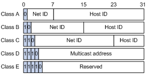
Table 1 IP address classes and ranges
|
Class |
Address range |
Remarks |
|
A |
0.0.0.0 to 127.255.255.255 |
The IP address 0.0.0.0 is used by a host at startup for temporary communication. This address is never a valid destination address. Addresses starting with 127 are reserved for loopback test. Packets destined to these addresses are processed locally as input packets rather than sent to the link. |
|
B |
128.0.0.0 to 191.255.255.255 |
N/A |
|
C |
192.0.0.0 to 223.255.255.255 |
N/A |
|
D |
224.0.0.0 to 239.255.255.255 |
Multicast addresses. |
|
E |
240.0.0.0 to 255.255.255.255 |
Reserved for future use except for the broadcast address 255.255.255.255. |
Special IP addresses
The following IP addresses are for special use and cannot be used as host IP addresses.
· IP address with an all-zero net ID—Identifies a host on the local network. For example, IP address 0.0.0.16 indicates the host with a host ID of 16 on the local network.
· IP address with an all-zero host ID—Identifies a network.
· IP address with an all-one host ID—Identifies a directed broadcast address. For example, a packet with the destination address of 192.168.1.255 is broadcast to all the hosts on the network 192.168.1.0.
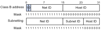
Subnetting and masking
Subnetting divides a network into smaller networks called subnets by using some bits of the host ID to create a subnet ID.
Masking identifies the boundary between the host ID and the combination of net ID and subnet ID. (When subnetting is not adopted, a mask identifies the boundary between the net ID and the host ID.)
Each subnet mask is made up of 32 bits, which correspond to the bits in an IP address. In a subnet mask, consecutive ones represent the net ID and subnet ID, and consecutive zeros represent the host ID.
Before being subnetted, Class A, B, and C networks use default masks (also called natural masks) 255.0.0.0, 255.255.0.0, and 255.255.255.0, respectively.
Figure 2 shows how a Class B network is subnetted.
Figure 2 Subnetting a Class B network
Subnetting increases the number of addresses that cannot be assigned to hosts. After being subnetted, a network can accommodate fewer hosts.
For example, a Class B network without subnetting can accommodate 1022 more hosts than the same network subnetted into 512 subnets.
· Without subnetting—65534 hosts (216 – 2). (The two deducted addresses are the broadcast address, which has an all-one host ID, and the network address, which has an all-zero host ID.)
· With subnetting—Using the first 9 bits of the host-id for subnetting provides 512 (29) subnets. However, only 7 bits remain available for the host ID. This allows 126 (27 – 2) hosts in each subnet, a total of 64512 hosts (512 × 126).
Assigning an IP address to an interface
You can assign an interface one primary address and multiple secondary addresses.
Generally, you only need to assign the primary address to an interface. In some cases, you must assign secondary IP addresses to the interface. For example, if the interface connects to two subnets, to enable the device to communicate with all hosts on the LAN, assign a primary IP address and a secondary IP address to the interface.
Configuration guidelines
Follow these guidelines when you assign an IP address to an interface:
· Each interface has only one primary IP address. A newly configured primary IP address overwrites the previous one.
· You cannot assign secondary IP addresses to an interface that obtains an IP address through DHCP or PPP address negotiation.
· The primary and secondary IP addresses you assign to the interface can be located on the same subnet, but different interfaces on your device must reside on different subnets.
· You can manually assign an IP address to an interface or configure the interface to obtain an IP address through DHCP or PPP address negotiation. If you change the way an interface obtains an IP address, the new IP address overwrites the previous one.
Configuration procedure
To assign an IP address to an interface:
|
Step |
Command |
Remarks |
|
1. Enter system view. |
system-view |
N/A |
|
2. Enter interface view. |
interface interface-type interface-number |
N/A |
|
3. Assign an IP address to the interface. |
ip address ip-address { mask-length | mask } [ sub ] |
By default, no IP address is assigned to any interface. |
IP address configuration example
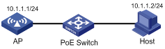
Network requirements
As shown in Figure 3, the IP address of VLAN-interface 1 on the AP is 10.1.1.1/24. The IP address of the host is 10.1.1.2/24. The AP and host are connected to the PoE switch.
On the host, telnet to the PoE-powered AP to manage the AP remotely.
Configuration procedure
# Assign an IP address to VLAN-interface 1.
<AP> system-view
[AP] interface vlan-interface 1
[AP-Vlan-interface1] ip address 10.1.1.1 24
[AP-Vlan-interface1] quit
# Configure Telnet.
# Set the authentication mode to password.
[AP] user-interface vty 0 4
[AP-ui-vty0-4] authentication-mode password
# Set the authentication password to admin in plain text.
[AP-ui-vty0-4] set authentication password simple admin
# Set the user level to 3.
[AP-ui-vty0-4] user privilege level 3
[AP-ui-vty0-4] quit
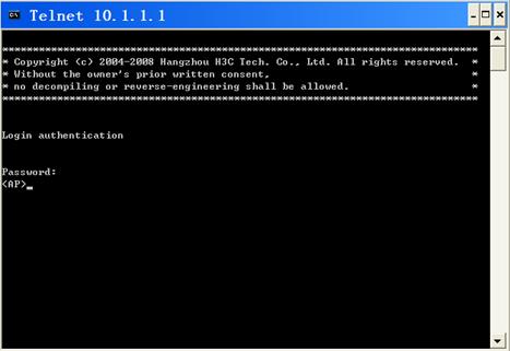
# Telnet to the AP from the host.
Displaying and maintaining IP addressing
|
Task |
Command |
Remarks |
|
Display IP configuration information for a specific Layer 3 interface or all Layer 3 interfaces. |
display ip interface [ interface-type interface-number ] [ | { begin | exclude | include } regular-expression ] |
Available in any view. |
|
Display brief IP configuration information for a specific Layer 3 interface or all Layer 3 interfaces. |
display ip interface [ interface-type [ interface-number ] ] brief [ | { begin | exclude | include } regular-expression ] |
Available in any view. |