- Table of Contents
-
- 04-Layer 3 Configuration Guide
- 00-Preface
- 01-Basic IP Routing Configuration
- 02-Static Routing Configuration
- 03-IPv6 Static Routing Configuration
- 04-IP Addressing Configuration
- 05-IPv6 Basics Configuration
- 06-DHCP Configuration
- 07-DHCPv6 Configuration
- 08-DNS Configuration
- 09-IPv6 DNS Configuration
- 10-IP Performance Optimization Configuration
- 11-ARP Configuration
- 12-IP Forwarding Basics Configuration
- 13-NAT Configuration
- Related Documents
-
| Title | Size | Download |
|---|---|---|
| 05-IPv6 Basics Configuration | 341.27 KB |
IPv6 neighbor discovery protocol
IPv6 basics configuration task list
Configuring basic IPv6 functions
Configuring an IPv6 global unicast address
Configuring an IPv6 link-local address
Configure an IPv6 anycast address
Configuring a static neighbor entry
Configuring the maximum number of neighbors dynamically learned
Setting the age timer for ND entries in stale state
Configuring parameters related to RA messages
Configuring the maximum number of attempts to send an NS message for DAD
Configuring path MTU discovery
Configuring a static path MTU for a specified IPv6 address
Configuring the aging time for dynamic path MTUs
Configuring IPv6 TCP properties
Configuring IPv6 FIB load sharing
Configuring ICMPv6 packet sending
Configuring the maximum ICMPv6 error packets sent in an interval
Enabling replying to multicast echo requests
Enabling sending of ICMPv6 time exceeded messages
Enabling sending of ICMPv6 destination unreachable messages
Enabling sending of ICMPv6 redirect messages
Displaying and maintaining IPv6 basics configuration
IPv6 basics configuration example
Troubleshooting IPv6 basics configuration
The term "router" in this document refers to both routers and access points.
Overview
IPv6, also called IP next generation (IPng), was designed by the IETF as the successor to IPv4. The significant difference between IPv6 and IPv4 is that IPv6 increases the IP address size from 32 bits to 128 bits.
IPv6 features
Simplified header format
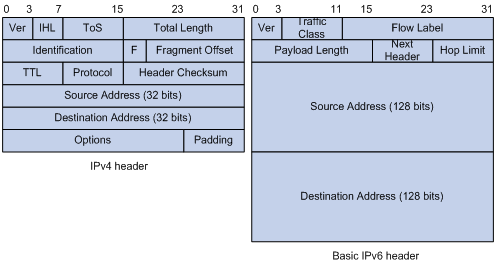
IPv6 removes several IPv4 header fields or moves them to the IPv6 extension headers to reduce the length of the basic IPv6 packet header. The basic IPv6 packet header has a fixed length of 40 bytes to simplify IPv6 packet handling and to improve forwarding efficiency. Although IPv6 address size is four times the IPv4 address size, the basic IPv6 packet header size is only twice the size of the option-less IPv4 packet header.
Figure 1 IPv4 packet header format and basic IPv6 packet header format
Larger address space
The source and destination IPv6 addresses are 128 bits (16 bytes) long. IPv6 can provide 3.4 x 1038 addresses to meet the requirements of hierarchical address division and the allocation of public and private addresses.
Hierarchical address structure
IPv6 uses the hierarchical address structure to speed up route lookups and reduce the IPv6 routing table size through route aggregation.
Address autoconfiguration
To simplify host configuration, IPv6 supports stateful and stateless address autoconfiguration:
· Stateful address autoconfiguration enables a host to acquire an IPv6 address and other configuration information from a server (for example, a DHCP server).
· Stateless address autoconfiguration enables a host to automatically generate an IPv6 address and other configuration information by using its link-layer address and the prefix information advertised by a router.
To communicate with other hosts on the same link, a host automatically generates a link-local address based on its link-layer address and the link-local address prefix (FE80::/10).
Built-in security
IPv6 defines extension headers to support IPsec. IPsec provides end-to-end security for network security solutions and enhances interoperability among different IPv6 applications.
QoS support
The Flow Label field in the IPv6 header allows the device to label the packets and facilitates the special handling of a flow.
Enhanced neighbor discovery mechanism
The IPv6 neighbor discovery protocol is implemented through a group of Internet Control Message Protocol version 6 (ICMPv6) messages to manage the information exchange among neighboring nodes on the same link. The group of ICMPv6 messages replaces Address Resolution Protocol (ARP) messages, Internet Control Message Protocol version 4 (ICMPv4) Router Discovery messages, and ICMPv4 Redirect messages and provides a series of other functions.
Flexible extension headers
IPv6 eliminates the Options field in the header and introduces optional extension headers to provide scalability and improve efficiency. The Options field in the IPv4 packet header contains up to 40 bytes, whereas the IPv6 extension headers are restricted to the maximum size of IPv6 packets.
IPv6 addresses
IPv6 address format
An IPv6 address is represented as a set of 16-bit hexadecimals separated by colons. An IPv6 address is divided into eight groups, and each 16-bit group is represented by four hexadecimal numbers, for example, 2001:0000:130F:0000:0000:09C0:876A:130B.
To simplify the representation of IPv6 addresses, you can handle zeros in IPv6 addresses by using the following methods:
· The leading zeros in each group can be removed. For example, the above address can be represented in a shorter format as 2001:0:130F:0:0:9C0:876A:130B.
· If an IPv6 address contains two or more consecutive groups of zeros, they can be replaced by a double colon (::). For example, the above address can be represented in the shortest format as 2001:0:130F::9C0:876A:130B.
|
|
CAUTION: A double colon may appear once or not at all in an IPv6 address. This limit allows the device to determine how many zeros the double colon represents, and correctly convert it to zeros to restore a 128-bit IPv6 address. |
An IPv6 address consists of an address prefix and an interface ID, which are equivalent to the network ID and the host ID of an IPv4 address respectively.
An IPv6 address prefix is written in IPv6-address/prefix-length notation, where the IPv6-address is represented in any of the formats previously mentioned and the prefix-length is a decimal number indicating how many leftmost bits of the IPv6 address comprises the address prefix.
IPv6 address types
IPv6 addresses fall into the following types:
· Unicast address—An identifier for a single interface, similar to an IPv4 unicast address. A packet sent to a unicast address is delivered to the interface identified by that address.
· Multicast address—An identifier for a set of interfaces (typically belonging to different nodes), similar to an IPv4 multicast address. A packet sent to a multicast address is delivered to all interfaces identified by that address.
There are no broadcast addresses in IPv6. Their function is replaced by multicast addresses.
· Anycast address—An identifier for a set of interfaces (typically belonging to different nodes). A packet sent to an anycast address is delivered to the nearest one of the interfaces identified by that address. The nearest interface is chosen according to the routing protocols' measure of distance.
The type of an IPv6 address is designated by the first several bits, called the format prefix. Table 1 lists the mappings between address types and format prefixes.
Table 1 Mappings between address types and format prefixes
|
Type |
Format prefix (binary) |
IPv6 prefix ID |
|
|
Unicast address |
Unspecified address |
00...0 (128 bits) |
::/128 |
|
Loopback address |
00...1 (128 bits) |
::1/128 |
|
|
Link-local address |
1111111010 |
FE80::/10 |
|
|
Site-local address |
1111111011 |
FEC0::/10 |
|
|
Global unicast address |
Other forms |
N/A |
|
|
Multicast address |
11111111 |
FF00::/8 |
|
|
Anycast address |
Anycast addresses use the unicast address space and have the identical structure of unicast addresses. |
||
Unicast addresses
Unicast addresses include global unicast addresses, link-local unicast addresses, site-local unicast addresses, the loopback address, and the unspecified address:
· Global unicast addresses, equivalent to public IPv4 addresses, are provided for network service providers. This type of address allows efficient prefix aggregation to restrict the number of global routing entries.
· Link-local addresses are used for communication among link-local nodes for neighbor discovery and stateless autoconfiguration. Packets with link-local source or destination addresses are not forwarded to other links.
· Site-local unicast addresses are similar to private IPv4 addresses. Packets with site-local source or destination addresses are not forwarded out of the local site (or a private network).
· A loopback address is 0:0:0:0:0:0:0:1 (or ::1). It cannot be assigned to any physical interface and can be used by a node to send an IPv6 packet to itself in the same way as the loopback address in IPv4.
· An unspecified address is 0:0:0:0:0:0:0:0 (or ::). It cannot be assigned to any node. Before acquiring a valid IPv6 address, a node fills this address in the source address field of IPv6 packets. The unspecified address cannot be used as a destination IPv6 address.
Multicast addresses
IPv6 multicast addresses listed in Table 2 are reserved for special purposes.
Table 2 Reserved IPv6 multicast addresses
|
Address |
Application |
|
FF01::1 |
Node-local scope all-nodes multicast address |
|
FF02::1 |
Link-local scope all-nodes multicast address |
|
FF01::2 |
Node-local scope all-routers multicast address |
|
FF02::2 |
Link-local scope all-routers multicast address |
|
FF05::2 |
Site-local scope all-routers multicast address |
Multicast addresses also include solicited-node addresses. A node uses a solicited-node multicast address to acquire the link-layer address of a neighboring node on the same link and to detect duplicate addresses. Each IPv6 unicast or anycast address has a corresponding solicited-node address. The format of a solicited-node multicast address is FF02:0:0:0:0:1:FFXX:XXXX. FF02:0:0:0:0:1:FF is fixed and consists of 104 bits, and XX:XXXX is the last 24 bits of an IPv6 unicast address or anycast address.
EUI-64 address-based interface identifiers
An interface identifier is 64 bits and uniquely identifies an interface on a link.
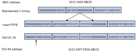
On an IEEE 802 interface (such as an Ethernet interface and a VLAN interface), the interface identifier is derived from the link-layer address (typically a MAC address) of the interface. The MAC address is 48-bit long. To obtain an EUI-64 address-based interface identifier, insert the hexadecimal number FFFE (16 bits of 1111111111111110) into the MAC address (behind the 24th high-order bit), and invert the universal/local (U/L) bit (which is the seventh high-order bit). This operation makes the interface identifier have the same local or global significance as the MAC address.
Figure 2 shows how an EUI-64 address-based interface identifier is generated from a MAC address.
Figure 2 Converting a MAC address into an EUI-64 address-based interface identifier
IPv6 neighbor discovery protocol
The IPv6 Neighbor Discovery (ND) protocol uses the following types of ICMPv6 messages to implement the following functions:
· Neighbor reachability detection
· Router/prefix discovery and address autoconfiguration
Table 3 lists the types and functions of ICMPv6 messages used by the ND protocol.
Table 3 ICMPv6 messages used by ND
|
ICMPv6 message |
Type |
Function |
|
Neighbor Solicitation (NS) message |
135 |
Acquires the link-layer address of a neighbor. |
|
Verifies whether a neighbor is reachable. |
||
|
Detects duplicate addresses. |
||
|
Neighbor Advertisement (NA) message |
136 |
Responds to an NS message. |
|
Notifies the neighboring nodes of link layer changes. |
||
|
Router Solicitation (RS) message |
133 |
Requests an address prefix and other configuration information for autoconfiguration after startup. |
|
Router Advertisement (RA) message |
134 |
Responds to an RS message. |
|
Advertises information, such as the Prefix Information options and flag bits. |
||
|
Redirect message |
137 |
Informs the source host of a better next hop on the path to a particular destination when certain conditions are satisfied. |
Address resolution
This function is similar to the ARP function in IPv4. An IPv6 node acquires the link-layer addresses of neighboring nodes on the same link through NS and NA message exchanges. Figure 3 shows how Host A acquires the link-layer address of Host B on a single link.
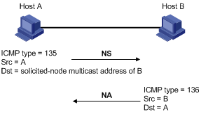
The address resolution operates as follows:
1. Host A multicasts an NS message. The source address of the NS message is the IPv6 address of the sending interface of Host A and the destination address is the solicited-node multicast address of Host B. The NS message contains the link-layer address of Host A.
2. After receiving the NS message, Host B determines whether the destination address of the packet is its solicited-node multicast address. If yes, Host B learns the link-layer address of Host A, and then unicasts an NA message containing its link-layer address.
3. Host A acquires the link-layer address of Host B from the NA message.
Neighbor reachability detection
After Host A acquires the link-layer address of its neighbor Host B, Host A can use NS and NA messages to check whether Host B is reachable.
1. Host A sends an NS message whose destination address is the IPv6 address of Host B.
2. If Host A receives an NA message from Host B, Host A decides that Host B is reachable. Otherwise, Host B is unreachable.
Duplicate address detection
After Host A acquires an IPv6 address, it performs Duplicate Address Detection (DAD) to check whether the address is being used by any other node (similar to the gratuitous ARP function in IPv4). DAD is accomplished through NS and NA message exchanges. Figure 4 shows the DAD process.
Figure 4 Duplicate address detection
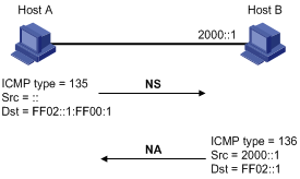
1. Host A sends an NS message whose source address is the unspecified address and whose destination address is the corresponding solicited-node multicast address of the IPv6 address to be detected. The NS message contains the IPv6 address.
2. If Host B uses this IPv6 address, Host B returns an NA message. The NA message contains the IPv6 address of Host B.
3. Host A learns that the IPv6 address is being used by Host B after receiving the NA message from Host B. If receiving no NA message, Host A decides that the IPv6 address is not in use and uses this address.
Router/prefix discovery and address autoconfiguration
Router/prefix discovery enables a node to locate the neighboring routers and to learn from the received RA message configuration parameters such as the prefix of the network where the node is located.
Stateless address autoconfiguration enables a node to generate an IPv6 address automatically according to the information obtained through router/prefix discovery.
Router/prefix discovery is implemented through RS and RA messages as follows:
1. At startup, a node sends an RS message to request the address prefix and other configuration information for autoconfiguration.
2. A router returns an RA message containing information such as Prefix Information options. (The router also periodically sends an RA message.)
In addition to an address prefix, the Prefix Information option also contains the preferred lifetime and valid lifetime of the address prefix. Nodes update the preferred lifetime and valid lifetime accordingly through periodic RA messages.
An automatically generated address is applicable within the valid lifetime and is removed when the valid lifetime expires.
Redirection
A newly started host may contain only a default route to the gateway in its routing table. When certain conditions are satisfied, the gateway sends an ICMPv6 Redirect message to the source host, so the host can select a better next hop to forward packets (similar to the ICMP redirection function in IPv4).
The gateway sends an ICMPv6 Redirect message when the following conditions are satisfied:
· The receiving interface is the forwarding interface.
· The selected route itself is not created or modified by an ICMPv6 Redirect message.
· The selected route is not the default route.
IPv6 path MTU discovery
The links that a packet passes from a source to a destination may have different MTUs. In IPv6, when the packet size exceeds the path MTU of a link, the packet is fragmented at the source end of the link to reduce the processing pressure on intermediate devices and to use network resources effectively.
The path MTU discovery mechanism is designed to find the minimum MTU of all links in the path between a source and a destination. Figure 5 shows how a source host discovers the path MTU to a destination host.
Figure 5 Path MTU discovery process
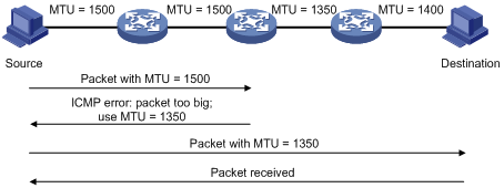
1. The source host compares its MTU with the packet to be sent, performs necessary fragmentation, and sends the resulting packet to the destination host.
2. If the MTU supported by a forwarding interface is smaller than the packet, the device discards the packet and returns an ICMPv6 error packet containing the interface MTU to the source host.
3. After receiving the ICMPv6 error packet, the source host uses the returned MTU to limit the packet size, performs fragmentation, and sends the resulting packet to the destination host.
4. Step 2 and step 3 are repeated until the destination host receives the packet. In this way, the source host decides the minimum MTU of all links in the path to the destination host.
IPv6 transition technologies
Before IPv6 dominates the Internet, highly efficient and seamless IPv6 transition technologies are needed to enable communication between IPv4 and IPv6 networks.
Dual stack is the most direct transition approach. A network node that supports both IPv4 and IPv6 is a dual stack node. A dual stack node configured with an IPv4 address and an IPv6 address can forward both IPv4 and IPv6 packets. For an upper layer application that supports both IPv4 and IPv6, either TCP or UDP can be selected at the transport layer, whereas the IPv6 stack is preferred at the network layer. Dual stack is suitable for communication between IPv4 nodes or between IPv6 nodes. It is the basis of all transition technologies. However, it does not solve the IPv4 address depletion issue because each dual stack node must have a globally unique IP address.
Protocols and standards
Protocols and standards related to IPv6 include:
· RFC 1881, IPv6 Address Allocation Management
· RFC 1887, An Architecture for IPv6 Unicast Address Allocation
· RFC 1981, Path MTU Discovery for IP version 6
· RFC 2375, IPv6 Multicast Address Assignments
· RFC 2460, Internet Protocol, Version 6 (IPv6) Specification
· RFC 2464, Transmission of IPv6 Packets over Ethernet Networks
· RFC 2526, Reserved IPv6 Subnet Anycast Addresses
· RFC 2894, Router Renumbering for IPv6
· RFC 3307, Allocation Guidelines for IPv6 Multicast Addresses
· RFC 3513, Internet Protocol Version 6 (IPv6) Addressing Architecture
· RFC 4191, Default Router Preferences and More-Specific Routes
· RFC 4443, Internet Control Message Protocol (ICMPv6) for the Internet Protocol Version 6 (IPv6) Specification
· RFC 4861, Neighbor Discovery for IP Version 6 (IPv6)
· RFC 4862, IPv6 Stateless Address Autoconfiguration
IPv6 basics configuration task list
|
Task |
Remarks |
|
|
Required |
||
|
Required to configure one |
||
|
Optional |
||
|
Configuring the maximum number of neighbors dynamically learned |
Optional |
|
|
Optional |
||
|
Optional |
||
|
Configuring the maximum number of attempts to send an NS message for DAD |
Optional |
|
|
Optional |
||
|
Optional |
||
|
Optional |
||
|
Optional |
||
|
Optional |
||
|
Configuring the maximum ICMPv6 error packets sent in an interval |
Optional |
|
|
Optional |
||
|
Optional |
||
|
Optional |
||
|
Optional |
||
Configuring basic IPv6 functions
Enabling IPv6
Enable IPv6 before you perform any IPv6-related configuration. Without IPv6 enabled, an interface cannot forward IPv6 packets even if it has an IPv6 address configured.
To enable IPv6:
|
Step |
Command |
Remarks |
|
1. Enter system view. |
system-view |
N/A |
|
2. Enable IPv6. |
ipv6 |
Disabled by default. |
Configuring an IPv6 global unicast address
Configure an IPv6 global unicast address by using the following options:
· EUI-64 IPv6 addressing—The IPv6 address prefix of an interface is manually configured, and the interface identifier is generated automatically by the interface.
· Manual configuration—The IPv6 global unicast address is configured manually.
· Stateless address autoconfiguration—The IPv6 global unicast address is generated automatically based on the address prefix information contained in the RA message.
· Prefix-generated address—The IPv6 global unicast address is generated automatically based on the applied IPv6 prefix, specified sub-prefix bit, and host bit information.
You can configure multiple IPv6 global unicast addresses with different prefixes on an interface.
A manually configured global unicast address takes precedence over an automatically generated one. If a global unicast address has been automatically generated on an interface when you manually configure another one with the same address prefix, the latter overwrites the previous. The overwritten automatic global unicast address is not restored even if the manual one is removed. Instead, a new global unicast address is automatically generated based on the address prefix information in the RA message that the interface receives at the next time.
EUI-64 IPv6 addressing
To configure an interface to generate an EUI-64 IPv6 address:
|
Step |
Command |
Remarks |
|
1. Enter system view. |
system-view |
N/A |
|
2. Enter interface view. |
interface interface-type interface-number |
N/A |
|
3. Configure the interface to generate an EUI-64 IPv6 address. |
ipv6 address ipv6-address/prefix-length eui-64 |
By default, no IPv6 global unicast address is configured on an interface. |
Manual configuration
To specify an IPv6 address manually for an interface:
|
Step |
Command |
Remarks |
|
1. Enter system view. |
system-view |
N/A |
|
2. Enter interface view. |
interface interface-type interface-number |
N/A |
|
3. Configure an IPv6 address manually. |
ipv6 address { ipv6-address prefix-length | ipv6-address/prefix-length } |
By default, no IPv6 global unicast address is configured on an interface. |
Stateless address autoconfiguration
To configure an interface to generate an IPv6 address by using stateless address autoconfiguration:
|
Step |
Command |
Remarks |
|
1. Enter system view. |
system-view |
N/A |
|
2. Enter interface view. |
interface interface-type interface-number |
N/A |
|
3. Configure an IPv6 address to be generated through stateless address autoconfiguration. |
ipv6 address auto |
By default, no IPv6 global unicast address is configured on an interface. Using the undo ipv6 address auto command on an interface removes all IPv6 global unicast addresses automatically generated on the interface. |
Applying a prefix to generate an IPv6 address
Before you apply a prefix to an interface to generate an IPv6 address, create an IPv6 prefix with one of the following methods:
· Use the ipv6 prefix command to create a static IPv6 prefix.
· Configure the device to use DHCPv6 for prefix acquisition. The client generates an IPv6 prefix with a specific ID based on the prefix obtained from the DHCPv6 server. For more information, see the ipv6 dhcp client pd command in Layer 3 Command Reference.
To apply an IPv6 prefix to an interface to generate an IPv6 address:
|
Step |
Command |
Remarks |
|
1. Enter system view. |
system-view |
N/A |
|
2. Create an IPv6 prefix. |
·
(Approach 1) Specify a static IPv6
prefix: ·
(Approach 2) Configure the device to
obtain an IPv6 prefix from the DHCPv6 server, and generate an IPv6 prefix
with a specific ID: |
Use either approach. By default, no IPv6 prefix is configured on the device. |
|
3. Enter interface view. |
interface interface-type interface-number |
N/A |
|
4. Apply a prefix to generate an IPv6 address. |
ipv6 address prefix-number sub-prefix/prefix-length |
By default, no prefix is applied for IPv6 address generation on an interface. |
Configuring an IPv6 link-local address
IPv6 link-local addresses can be configured in either of the following ways:
· Automatic generation—The device automatically generates a link-local address for an interface according to the link-local address prefix (FE80::/10) and the link-layer address of the interface.
· Manual assignment—IPv6 link-local addresses can be assigned manually.
An interface can have only one link-local address. To avoid link-local address conflicts, use the automatic generation method.
Manual assignment takes precedence over automatic generation.
· If you first use automatic generation and then manual assignment, the manually assigned link-local address overwrites the automatically generated one.
· If you first use manual assignment and then automatic generation, the automatically generated link-local address does not take effect and the link-local address is still the manually assigned one. If you delete the manually assigned address, the automatically generated link-local address is validated.
To configure automatic generation of an IPv6 link-local address for an interface:
|
Step |
Command |
Remarks |
|
1. Enter system view. |
system-view |
N/A |
|
2. Enter interface view. |
interface interface-type interface-number |
N/A |
|
3. Configure the interface to automatically generate an IPv6 link-local address. |
ipv6 address auto link-local |
Optional. By default, no link-local address is configured on an interface. After an IPv6 global unicast address is configured on the interface, a link-local address is generated automatically. |
To manually configure an IPv6 link-local address:
|
Step |
Command |
Remarks |
|
1. Enter system view. |
system-view |
N/A |
|
2. Enter interface view. |
interface interface-type interface-number |
N/A |
|
3. Configure an IPv6 link-local address manually. |
ipv6 address ipv6-address link-local |
Optional. By default, no link-local address is configured on an interface. After an IPv6 global unicast address is configured on the interface, a link-local address is generated automatically. |
After an IPv6 global unicast address is configured for an interface, a link-local address is generated automatically. The automatically generated link-local address is the same as the one generated by using the ipv6 address auto link-local command. If a link-local address is manually assigned to an interface, this manual link-local address takes effect. If the manually assigned link-local address is removed, the automatically generated link-local address takes effect.
The undo ipv6 address auto link-local command only removes the link-local addresses generated through the ipv6 address auto link-local command. However, if an IPv6 global unicast address is already configured for an interface, the interface still has a link-local address because the system automatically generates one for the interface. If no IPv6 global unicast address is configured, the interface has no link-local address.
Configure an IPv6 anycast address
|
Step |
Command |
Remarks |
|
1. Enter system view. |
system-view |
N/A |
|
2. Enter interface view. |
interface interface-type interface-number |
N/A |
|
3. Configure an IPv6 anycast address. |
ipv6 address ipv6-address/prefix-length anycast |
Optional. By default, no IPv6 anycast address is configured on an interface. |
Configuring IPv6 ND
Configuring a static neighbor entry
The IPv6 address of a neighboring node can be resolved into a link-layer address dynamically through NS and NA messages or through a manually configured static neighbor entry.
The device uniquely identifies a static neighbor entry by the neighbor's IPv6 address and the local Layer 3 interface number. You can configure a static neighbor entry by associating a neighbor IPv6 address and link-layer address with a port in a VLAN containing the local node. Make sure the corresponding VLAN interface exists and that the Layer 2 port specified by port-type port-number belongs to the VLAN specified by vlan-id. The device associates the VLAN interface with the neighbor IPv6 address to identify the static neighbor entry.
To configure a static neighbor entry:
|
Step |
Command |
Remarks |
|
1. Enter system view. |
system-view |
N/A |
|
2. Configure a static neighbor entry. |
ipv6 neighbor ipv6-address mac-address { vlan-id port-type port-number | interface interface-type interface-number } |
By default, no static neighbor entry exists on the device. |
Configuring the maximum number of neighbors dynamically learned
The device can dynamically acquire the link-layer address of a neighboring node through NS and NA messages and add it into the neighbor table. A large table may reduce the forwarding performance of the device. You can restrict the size of the neighbor table by setting the maximum number of neighbors that an interface can dynamically learn. When the number of dynamically learned neighbors reaches the threshold, the interface stops learning neighbor information.
To configure the maximum number of neighbors dynamically learned:
|
Step |
Command |
Remarks |
|
1. Enter system view. |
system-view |
N/A |
|
2. Enter interface view. |
interface interface-type interface-number |
N/A |
|
3. Configure the maximum number of neighbors which can be dynamically learned by an interface. |
ipv6 neighbors max-learning-num number |
Optional. By default, a Layer 2 interface does not limit the number of neighbors dynamically learned. A Layer 3 interface can dynamically learn a maximum of 256 neighbors. |
Setting the age timer for ND entries in stale state
ND entries in stale state have an age timer. If an ND entry in stale state is not refreshed before the timer expires, it transits to the delay state. If it is still not refreshed in five seconds, the ND entry transits to the probe state, and the device sends an NS message for detection. If no response is received, the device removes the ND entry.
To set the age timer for ND entries in stale state:
|
Step |
Command |
Remarks |
|
1. Enter system view. |
system-view |
N/A |
|
2. Set the age timer for ND entries in stale state. |
ipv6 neighbor stale-aging aging-time |
Optional. Four hours by default. |
Configuring parameters related to RA messages
You can enable an interface to send RA messages, and configure the interval for sending RA messages and parameters in RA messages. After receiving an RA message, a host can use these parameters to perform corresponding operations. Table 4 lists and describes the configurable parameters in an RA message.
Table 4 Parameters in an RA message and their descriptions
|
Parameters |
Description |
|
Cur Hop Limit |
When sending an IPv6 packet, a host uses the value to fill the Hop Limit field in IPv6 headers. The value is also filled into the Hop Limit field in the response packet of a device. |
|
Prefix Information options |
After receiving the prefix information, the hosts on the same link can perform stateless autoconfiguration. |
|
MTU |
Guarantees that all nodes on a link use the same MTU value. |
|
M flag |
Determines whether hosts use the stateful autoconfiguration to acquire IPv6 addresses. If the M flag is set to 1, hosts use the stateful autoconfiguration (for example, through a DHCP server) to acquire IPv6 addresses. Otherwise, hosts use the stateless autoconfiguration to acquire IPv6 addresses and generate IPv6 addresses according to their own link-layer addresses and the obtained prefix information. |
|
O flag |
Determines whether hosts use stateful autoconfiguration to acquire other configuration information. If the O flag is set to 1, hosts use stateful autoconfiguration (for example, through a DHCP server) to acquire other configuration information. Otherwise, hosts use stateless autoconfiguration to acquire other configuration information. |
|
Router Lifetime |
This field tells the receiving hosts how long the advertising device can live. |
|
Retrans Timer |
If the device fails to receive a response message within the specified time after sending an NS message, it retransmits the NS message. |
|
Reachable Time |
If the neighbor reachability detection shows that a neighbor is reachable, the device considers the neighbor reachable within the specified reachable time. If the device must send a packet to the neighbor after the specified reachable time expires, the device reconfirms whether the neighbor is reachable. |
The maximum interval for sending RA messages should be less than (or equal to) the router lifetime in RA messages, so the router can be updated through an RA message before expiration.
The values of the NS retransmission timer and the reachable time configured for an interface are sent to hosts through RA messages. Furthermore, this interface sends NS messages at the interval of the NS retransmission timer and considers a neighbor reachable within the reachable time.
Enabling sending of RA messages
|
Step |
Command |
Remarks |
|
1. Enter system view. |
system-view |
N/A |
|
2. Enter interface view. |
interface interface-type interface-number |
N/A |
|
3. Disable RA message suppression. |
undo ipv6 nd ra halt |
By default, RA messages are suppressed. |
|
4. Configure the maximum and minimum intervals for sending RA messages. |
ipv6 nd ra interval max-interval-value min-interval-value |
Optional. By default, the maximum interval for sending RA messages is 600 seconds, and the minimum interval is 200 seconds. The device sends RA messages at random intervals between the maximum interval and the minimum interval. The minimum interval should be less than or equal to 0.75 times the maximum interval. |
Configuring parameters related to RA messages
|
Step |
Command |
Remarks |
|
1. Enter system view. |
system-view |
N/A |
|
2. Configure the hop limit. |
ipv6 nd hop-limit value |
Optional. 64 by default. |
|
3. Enter interface view. |
interface interface-type interface-number |
N/A |
|
4. Configure the prefix information in RA messages. |
ipv6 nd ra prefix { ipv6-prefix prefix-length | ipv6-prefix/prefix-length } valid-lifetime preferred-lifetime [ no-autoconfig | off-link ] * |
Optional. By default, no prefix information is configured for RA messages, and the IPv6 address of the interface sending RA messages is used as the prefix information with valid lifetime 2592000 seconds (30 days) and preferred lifetime 604800 seconds (seven days). |
|
5. Turn off the MTU option in RA messages. |
ipv6 nd ra no-advlinkmtu |
Optional. By default, RA messages contain the MTU option. |
|
6. Set the M flag bit to 1. |
ipv6 nd autoconfig managed-address-flag |
Optional. By default, the M flag bit is set to 0 and hosts acquire IPv6 addresses through stateless autoconfiguration. |
|
7. Set the O flag bit to 1. |
ipv6 nd autoconfig other-flag |
Optional. By default, the O flag bit is set to 0 and hosts acquire other configuration information through stateless autoconfiguration. |
|
8. Configure the router lifetime in RA messages. |
ipv6 nd ra router-lifetime value |
Optional. The default setting is 1800 seconds. |
|
9. Set the NS retransmission timer. |
ipv6 nd ns retrans-timer value |
Optional. By default, the local interface sends NS messages at 1000 millisecond intervals, and the value of the Retrans Timer field in RA messages sent by the local interface is 0. The interval for retransmitting an NS message is determined by the receiving device. |
|
10. Set the reachable time. |
ipv6 nd nud reachable-time value |
Optional. By default, the neighbor reachable time on the local interface is 30000 milliseconds, and the value of the Reachable Time field in the RA messages sent by the local interface is 0. The neighbor reachable time is determined by the receiving device. |
Configuring the maximum number of attempts to send an NS message for DAD
An interface sends an NS message for DAD after acquiring an IPv6 address. If the interface does not receive a response within a specified time (determined by the ipv6 nd ns retrans-timer command), it continues to send an NS message. If the interface still does not receive a response after the number of sent attempts reaches the threshold (specified with the ipv6 nd dad attempts command), the acquired address is considered usable.
To configure the attempts to send an NS message for DAD:
|
Step |
Command |
Remarks |
|
1. Enter system view. |
system-view |
N/A |
|
2. Enter interface view. |
interface interface-type interface-number |
N/A |
|
3. Configure the number of attempts to send an NS message for DAD. |
ipv6 nd dad attempts value |
Optional. 1 by default. When the value argument is set to 0, DAD is disabled. |
Enabling local ND proxy
Local ND proxy supports the NS and NA messages only.
About local ND proxy
If a host sends an NS message requesting the hardware address of another host that is isolated from the sending host at Layer 2, the device in between must be able to forward the NS message to allow Layer 3 communication between the two hosts. This is achieved by ND proxy. ND proxy varies with application scenarios. In the following case, local ND proxy is applied.
As shown in Figure 6, both Host A and Host B belong to VLAN 2, but they connect to Ethernet 1/3 and Ethernet 1/1 respectively, which are isolated at Layer 2.
Figure 6 Application environment of local ND proxy
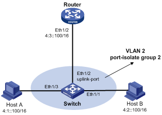
Because Host A's IPv6 address is on the same subnet as Host B's, Host A directly sends an NS message to obtain Host B's MAC address. However, Host B cannot receive the NS message because they are isolated at Layer 2.
To solve this problem, enable local ND proxy on Ethernet 1/2 of the router so that the router can forward messages between Host A and Host B.
Local ND proxy implements Layer 3 communication for two hosts in the following cases:
· The two hosts must connect to different isolated Layer 2 ports of a VLAN.
· If super VLAN is used, the two hosts must belong to different sub VLANs.
· If isolate-user-VLAN is used, the two hosts must belong to different secondary VLANs.
Configuration procedure
You can enable local ND proxy only in VLAN interface view.
To enable local ND proxy:
|
Step |
Command |
Remarks |
|
1. Enter system view. |
system-view |
N/A |
|
2. Enter interface view. |
interface interface-type interface-number |
N/A |
|
3. Enable local ND proxy. |
local-proxy-nd enable |
Disabled by default. |
Configuring path MTU discovery
This section describes how to configure path MTU discovery.
Configuring a static path MTU for a specified IPv6 address
You can configure a static path MTU for a specified destination IPv6 address. When a source host sends a packet through an interface, it compares the interface MTU with the static path MTU of the specified destination IPv6 address. If the packet size is larger than the smaller one of the two values, the host fragments the packet according to the smaller value.
To configure a static path MTU for a specified IPv6 address:
|
Step |
Command |
Remarks |
|
1. Enter system view. |
system-view |
N/A |
|
2. Configure a static path MTU for a specified IPv6 address. |
ipv6 pathmtu ipv6-address [ value ] |
Not configured by default. |
Configuring the aging time for dynamic path MTUs
After the path MTU from a source host to a destination host is dynamically determined (see "Configuring path MTU discovery"), the source host sends subsequent packets to the destination host based on this MTU. After the aging time expires, the dynamic path MTU is removed and the source host re-determines a dynamic path MTU through the path MTU mechanism.
The aging time is invalid for a static path MTU.
To configure the aging time for dynamic path MTUs:
|
Step |
Command |
Remarks |
|
1. Enter system view. |
system-view |
N/A |
|
2. Configure the aging time for dynamic path MTUs. |
ipv6 pathmtu age age-time |
Optional. 10 minutes by default. |
Configuring IPv6 TCP properties
You can configure the following IPv6 TCP properties:
· synwait timer—When a SYN packet is sent, the synwait timer is triggered. If no response packet is received before the synwait timer expires, the IPv6 TCP connection establishment fails.
· finwait timer—When the IPv6 TCP connection status is FIN_WAIT_2, the finwait timer is triggered. If no packet is received before the finwait timer expires, the IPv6 TCP connection is terminated. If a FIN packet is received, the IPv6 TCP connection status becomes TIME_WAIT. If non-FIN packets are received, the finwait timer is reset upon receipt of the last non-FIN packet and the connection is terminated after the finwait timer expires.
· Size of the IPv6 TCP sending/receiving buffer.
To configure IPv6 TCP properties:
|
Step |
Command |
Remarks |
|
1. Enter system view. |
system-view |
N/A |
|
2. Set the synwait timer. |
tcp ipv6 timer syn-timeout wait-time |
Optional. 75 seconds by default. |
|
3. Set the finwait timer. |
tcp ipv6 timer fin-timeout wait-time |
Optional. 675 seconds by default. |
|
4. Set the size of the IPv6 TCP sending/receiving buffer. |
tcp ipv6 window size |
Optional. 8 KB by default. |
Configuring IPv6 FIB load sharing
In the IPv6 FIB load sharing mode, the device can decide how to select equal cost multi-paths (ECMP) to forward packets. The device supports the following load sharing modes:
· Load sharing based on the HASH algorithm—An algorithm based on the source IPv6 address and destination IPv6 address is adopted to select an ECMP route to forward packets.
· Load sharing based on polling—Each ECMP route is used in turn to forward packets.
To configure the IPv6 FIB load sharing:
|
Step |
Command |
Remarks |
|
1. Enter system view. |
system-view |
N/A |
|
2. Configure the IPv6 FIB load sharing mode. |
·
Configure load sharing based on the
hash algorithm: ·
Configure load sharing based on polling: |
Optional. By default, load sharing based on polling is adopted and ECMP routes are used in turn to forward packets. |
Configuring ICMPv6 packet sending
This section describes how to configure ICMPv6 packet sending.
Configuring the maximum ICMPv6 error packets sent in an interval
If too many ICMPv6 error packets are sent within a short period of time in a network, network congestion may occur. To avoid network congestion, you can control the maximum number of ICMPv6 error packets sent within a specified time by adopting the token bucket algorithm.
You can set the capacity of a token bucket to determine the number of tokens in the bucket. In addition, you can set the update interval of the token bucket, that is, the interval for restoring the configured capacity. One token allows one ICMPv6 error packet to be sent. Each time an ICMPv6 error packet is sent, the number of tokens in a token bucket decreases by one. If the number of ICMPv6 error packets successively sent exceeds the capacity of the token bucket, the additional ICMPv6 error packets cannot be sent out until the capacity of the token bucket is restored.
To configure the capacity and update interval of the token bucket:
|
Step |
Command |
Remarks |
|
1. Enter system view. |
system-view |
N/A |
|
2. Configure the capacity and update interval of the token bucket. |
ipv6 icmp-error { bucket bucket-size | ratelimit interval } * |
Optional. By default, the capacity of a token bucket is 10 and the update interval is 100 milliseconds. A maximum of 10 ICMPv6 error packets can be sent within 100 milliseconds. The update interval "0" indicates that the number of ICMPv6 error packets sent is not restricted. |
Enabling replying to multicast echo requests
If hosts are configured to answer multicast echo requests, an attacker may use this mechanism to attack a host. For example, if Host A (an attacker) sends an echo request with the source being Host B to a multicast address, all the hosts in the multicast group send echo replies to Host B. To prevent such an attack, disable a device from answering multicast echo requests by default. In some application scenarios, however, you need to enable the device to answer multicast echo requests.
To enable replying to multicast echo requests:
|
Step |
Command |
Remarks |
|
1. Enter system view. |
system-view |
N/A |
|
2. Enable replying to multicast echo requests. |
ipv6 icmpv6 multicast-echo-reply enable |
The device is disabled from replying to multicast echo requests. |
Enabling sending of ICMPv6 time exceeded messages
A device sends out an ICMPv6 Time Exceeded message in the following cases:
· If a received IPv6 packet's destination IP address is not a local address and its hop limit is 1, the device sends an ICMPv6 Hop Limit Exceeded message to the source.
· Upon receiving the first fragment of an IPv6 datagram with the destination IP address being the local address, the device starts a timer. If the timer expires before all the fragments arrive, an ICMPv6 Fragment Reassembly Timeout message is sent to the source.
If large quantities of malicious packets are received, the performance of a device degrades greatly because it must send back ICMP Time Exceeded messages. You can disable sending of ICMPv6 Time Exceeded messages.
To enable sending of ICMPv6 time exceeded messages:
|
Step |
Command |
Remarks |
|
1. Enter system view. |
system-view |
N/A |
|
2. Enable sending of ICMPv6 Time Exceeded messages. |
ipv6 hoplimit-expires enable |
Optional. Enabled by default. |
Enabling sending of ICMPv6 destination unreachable messages
If the device fails to forward a received IPv6 packet because of one of the following reasons, it drops the packet and sends a corresponding ICMPv6 Destination Unreachable error message to the source.
· If no route is available for forwarding the packet, the device sends a "no route to destination" ICMPv6 error message to the source.
· If the device fails to forward the packet because of an administrative prohibition (such as a firewall filter or an ACL), the device sends the source a "destination network administratively prohibited" ICMPv6 error message.
· If the device fails to deliver the packet because the destination is beyond the scope of the source IPv6 address (for example, the source IPv6 address of the packet is a link-local address whereas the destination IPv6 address of the packet is a global unicast address), the device sends the source a "beyond scope of source address" ICMPv6 error message.
· If the device fails to resolve the corresponding link layer address of the destination IPv6 address, the device sends the source an "address unreachable" ICMPv6 error message.
· If the packet with the destination being local and transport layer protocol being UDP and the packet's destination port number does not match the running process, the device sends the source a "port unreachable" ICMPv6 error message.
If an attacker sends abnormal traffic that causes the device to generate ICMPv6 destination unreachable messages, end users may be affected. To prevent such attacks, you can disable the device from sending ICMPv6 destination unreachable messages.
To enable sending of ICMPv6 destination unreachable messages:
|
Step |
Command |
Remarks |
|
1. Enter system view. |
system-view |
N/A |
|
2. Enable sending of ICMPv6 destination unreachable messages. |
ipv6 unreachables enable |
Disabled by default. |
Enabling sending of ICMPv6 redirect messages
When a device receives a large number of attack packets that require the device to send ICMPv6 redirect packets, the device's performance is degraded for processing these packets. To protect the device from such attacks, you can use the undo form of the following command to disable sending of ICMPV6 redirect packets.
To enable sending of ICMPv6 redirect messages:
|
Step |
Command |
Remarks |
|
1. Enter system view |
system-view |
N/A |
|
2. Enable sending of ICMPv6 redirect messages |
ipv6 redirects enable |
Optional. By default, this function is disabled. |
Displaying and maintaining IPv6 basics configuration
|
Task |
Command |
Remarks |
|
Display IPv6 FIB entries. |
display ipv6 fib [ acl6 acl6-number | ipv6-prefix ipv6-prefix-name ] [ | { begin | exclude | include } regular-expression ] |
Available in any view. |
|
Display the IPv6 FIB entry of a specified destination IPv6 address. |
display ipv6 fib ipv6-address [ prefix-length ] [ | { begin | exclude | include } regular-expression ] |
Available in any view. |
|
Display the IPv6 information of an interface. |
display ipv6 interface [ interface-type [ interface-number ] ] [ brief ] [ | { begin | exclude | include } regular-expression ] |
Available in any view. |
|
Display IPv6 prefixes information. |
display ipv6 prefix [ prefix-number ] [ | { begin | exclude | include } regular-expression ] |
Available in any view. |
|
Display neighbor information. |
display ipv6 neighbors { ipv6-address | all | dynamic | interface interface-type interface-number | static | vlan vlan-id } [ verbose ] [ | { begin | exclude | include } regular-expression ] |
Available in any view. |
|
Display the total number of neighbor entries satisfying the specified conditions. |
display ipv6 neighbors { all | dynamic | interface interface-type interface-number | static | vlan vlan-id } count [ | { begin | exclude | include } regular-expression ] |
Available in any view. |
|
Display the IPv6 path MTU information. |
display ipv6 pathmtu { ipv6-address | all | dynamic | static } [ | { begin | exclude | include } regular-expression ] |
Available in any view. |
|
Display socket information. |
display ipv6 socket [ socktype socket-type ] [ task-id socket-id ] [ | { begin | exclude | include } regular-expression ] |
Available in any view. |
|
Display the statistics of IPv6 packets and ICMPv6 packets. |
display ipv6 statistics [ | { begin | exclude | include } regular-expression ] |
Available in any view. |
|
Display IPv6 TCP connection statistics. |
display tcp ipv6 statistics [ | { begin | exclude | include } regular-expression ] |
Available in any view. |
|
Display IPv6 TCP connection status information. |
display tcp ipv6 status [ | { begin | exclude | include } regular-expression ] |
Available in any view. |
|
Display the statistics of IPv6 UDP packets. |
display udp ipv6 statistics [ | { begin | exclude | include } regular-expression ] |
Available in any view. |
|
Clear IPv6 neighbor information. |
reset ipv6 neighbors { all | dynamic | interface interface-type interface-number | static } |
Available in user view. |
|
Clear the path MTU values. |
reset ipv6 pathmtu { all | static | dynamic} |
Available in user view. |
|
Clear the statistics of IPv6 and ICMPv6 packets. |
reset ipv6 statistics |
Available in user view. |
|
Clear all IPv6 TCP connection statistics. |
reset tcp ipv6 statistics |
Available in user view. |
|
Clear the statistics of all IPv6 UDP packets. |
reset udp ipv6 statistics |
Available in user view. |
IPv6 basics configuration example
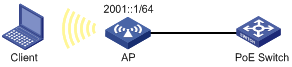
Network requirements
As shown in Figure 7, the client and AP are connected to the PoE switch through Ethernet ports. The global unicast address of VLAN-interface 1 on the AP is 2001::1/64.
Enable IPv6 on the client to automatically generate an IPv6 address through IPv6 ND protocol.
Configuration procedure
1. Configure the AP:
# Enable the IPv6 packet forwarding function.
<AP> system-view
[AP] ipv6
# Configure a global unicast address for VLAN-interface 1 and allow it to advertise RA messages.
[AP] interface vlan-interface 1
[AP-Vlan-interface1] ipv6 address 2001::1/64
[AP-Vlan-interface1] undo ipv6 nd ra halt
2. Configure the client:
Enable IPv6 for the client to automatically generate an IPv6 address through IPv6 NDP. (Details not shown.)
Verifying the configuration
# Ping the AP from the client to verify the connectivity.
C:\Documents and Settings\Administrator>ping6 2001::1
Pinging 2001::1
from 2001::9b1:f2a6:2d45:d77d with 32 bytes of data:
Reply from 2001::1: bytes=32 time=1ms
Reply from 2001::1: bytes=32 time<1ms
Reply from 2001::1: bytes=32 time<1ms
Reply from 2001::1: bytes=32 time<1ms
Ping statistics for 2001::1:
Packets: Sent = 4, Received = 4, Lost = 0 (0% loss),
Approximate round trip times in milli-seconds:
Minimum = 0ms, Maximum = 1ms, Average = 0ms
Troubleshooting IPv6 basics configuration
Symptom
The peer IPv6 address cannot be pinged.
Solution
1. Use the display current-configuration command in any view or the display this command in system view to verify that IPv6 is enabled. For more information about the display current-configuration command, see Fundamentals Configuration Guide.
2. Use the display ipv6 interface command in any view to verify that the IPv6 address of the interface is correct and the interface is up.
3. Use the debugging ipv6 packet command in user view to enable the debugging for IPv6 packets to help locate the cause.