- Table of Contents
-
- 04-Layer 3 Configuration Guide
- 00-Preface
- 01-Basic IP Routing Configuration
- 02-Static Routing Configuration
- 03-IPv6 Static Routing Configuration
- 04-IP Addressing Configuration
- 05-IPv6 Basics Configuration
- 06-DHCP Configuration
- 07-DHCPv6 Configuration
- 08-DNS Configuration
- 09-IPv6 DNS Configuration
- 10-IP Performance Optimization Configuration
- 11-ARP Configuration
- 12-IP Forwarding Basics Configuration
- 13-NAT Configuration
- Related Documents
-
| Title | Size | Download |
|---|---|---|
| 06-DHCP Configuration | 396.04 KB |
Dynamic IP address allocation process
IP address allocation sequence
DHCP server configuration task list
Configuring an address pool on the DHCP server
Configuring address allocation mode for a common address pool
Configuring dynamic address allocation for an extended address pool
Configuring a domain name suffix for the client
Configuring DNS servers for the client
Configuring WINS servers and NetBIOS node type for the client
Configuring BIMS server information for the client
Configuring gateways for the client
Configuring Option 184 parameters for the client with voice service
Configuring the TFTP server and bootfile name for the client
Specifying a server's IP address for the DHCP client
Configuring self-defined DHCP options
Enabling the DHCP server on an interface
Applying an extended address pool on an interface
Configuring the DHCP server security functions
Enabling unauthorized DHCP server detection
Configuring IP address conflict detection
Enabling client offline detection
Enabling handling of Option 82
Specifying the threshold for sending trap messages
Displaying and maintaining the DHCP server
DHCP server configuration examples
Static IP address assignment configuration example
Dynamic IP address assignment configuration example
Self-defined option configuration example
Troubleshooting DHCP server configuration
Enabling the DHCP client on an interface
Displaying and maintaining the DHCP client
DHCP client configuration example
The Dynamic Host Configuration Protocol (DHCP) provides a framework to assign configuration information to network devices.
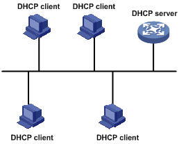
Figure 1 shows a typical DHCP application scenario where the DHCP clients and the DHCP server reside on the same subnet.
Figure 1 A typical DHCP application
DHCP address allocation
Allocation mechanisms
DHCP supports the following mechanisms for IP address allocation:
· Static allocation—The network administrator assigns an IP address to a client (for example, a WWW server), and DHCP conveys the assigned address to the client.
· Automatic allocation—DHCP assigns a permanent IP address to a client.
· Dynamic allocation—DHCP assigns an IP address to a client for a limited period of time, which is called a lease. Most DHCP clients obtain their addresses in this way.
Dynamic IP address allocation process
Figure 2 Dynamic IP address allocation process
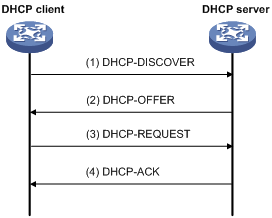
1. The client broadcasts a DHCP-DISCOVER message to locate a DHCP server.
2. Each DHCP server offers configuration parameters such as an IP address to the client in a DHCP-OFFER message. The sending mode of the DHCP-OFFER is determined by the flag field in the DHCP-DISCOVER message. For related information, see "DHCP message format."
3. If several DHCP servers send offers to the client, the client accepts the first received offer, and broadcasts it in a DHCP-REQUEST message to formally request the IP address.
4. All DHCP servers receive the DHCP-REQUEST message, but only the server selected by the client returns a DHCP-ACK message to confirm that the IP address has been allocated to the client, or a DHCP-NAK message to deny the IP address allocation.
¡ After the client receives the DHCP-ACK message, it broadcasts a gratuitous ARP packet to verify whether the IP address assigned by the server is already in use.
¡ If the client receives no response within the specified time, the client uses the assigned IP address. Otherwise, the client sends a DHCP-DECLINE message to the server to request an IP address again.
IP addresses offered by other DHCP servers can be assigned to other clients.
IP address lease extension
A dynamically assigned IP address has a lease. When the lease expires, the IP address is reclaimed by the DHCP server. To continue using the IP address, the client must extend the lease duration.
When 1/2 lease duration elapses, the DHCP client unicasts a DHCP-REQUEST to the DHCP server to extend the lease. Depending on the availability of the IP address, the DHCP server returns either a DHCP-ACK unicast confirming that the client's lease duration has been extended, or a DHCP-NAK unicast denying the request.
If the client receives no reply, it broadcasts another DHCP-REQUEST message for lease extension after 7/8 of the lease duration elapses. Again, depending on the availability of the IP address, the DHCP server returns either a DHCP-ACK unicast confirming that the client's lease duration has been extended, or a DHCP-NAK unicast denying the request.
DHCP message format
Figure 3 shows the DHCP message format, which is based on the BOOTP message format although DHCP uses some of the fields in significantly different ways. The numbers in parentheses indicate the size of each field in bytes.
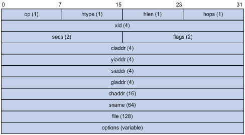
· op—Message type defined in option field. 1 = REQUEST, 2 = REPLY
· htype, hlen—Hardware address type and length of the DHCP client.
· hops—Number of relay agents a request message traveled.
· xid—Transaction ID, a random number chosen by the client to identify an IP address allocation.
· secs—Filled in by the client, the number of seconds elapsed since the client began address acquisition or renewal process. This field is reserved and set to 0.
· flags—The leftmost bit is defined as the BROADCAST (B) flag. If this flag is set to 0, the DHCP server sent a reply back by unicast. If this flag is set to 1, the DHCP server sent a reply back by broadcast. The remaining bits of the flags field are reserved for future use.
· ciaddr—Client IP address if the client has an IP address that is valid and usable. Otherwise, it is set to zero. (The client does not use this field to request a specific IP address to lease.)
· yiaddr—"Your" (client) IP address, assigned by the server.
· siaddr—Server IP address, from which the client obtained configuration parameters.
· giaddr—(Gateway) IP address of the first relay agent a request message traveled.
· chaddr—Client hardware address.
· sname—Server host name, from which the client obtained configuration parameters.
· file—Bootfile name and path information, defined by the server to the client.
· options—Optional parameters field that is variable in length, which includes the message type, lease duration, subnet mask, domain name server IP address, and WINS IP address.
DHCP options
DHCP uses the same message format as BOOTP, but DHCP uses the Option field to carry information for dynamic address allocation and to provide additional configuration information to clients.
Common DHCP options
The following are common DHCP options:
· Option 3—Router option. It specifies the gateway address.
· Option 6—DNS server option. It specifies the DNS server's IP address.
· Option 33—Static route option. It specifies a list of classful static routes (the destination addresses in these static routes are classful) that a client should add into its routing table. If both Option 33 and Option 121 exist, Option 33 is ignored.
· Option 51—IP address lease option.
· Option 53—DHCP message type option. It identifies the type of the DHCP message.
· Option 55—Parameter request list option. It is used by a DHCP client to request specified configuration parameters. The option contains values that correspond to the parameters requested by the client.
· Option 60—Vendor class identifier option. It is used by a DHCP client to identify its vendor, and by a DHCP server to distinguish DHCP clients by vendor class and assign specific IP addresses to the DHCP clients.
· Option 66—TFTP server name option. It specifies a TFTP server to be assigned to the client.
· Option 67—Bootfile name option. It specifies the bootfile name to be assigned to the client.
· Option 121—Classless route option. It specifies a list of classless static routes (the destination addresses in these static routes are classless) that the requesting client should add to its routing table. If both Option 33 and Option 121 exist, Option 33 is ignored.
· Option 150—TFTP server IP address option. It specifies the TFTP server IP address to be assigned to the client.
For more information about DHCP options, see RFC 2132 and RFC 3442.
Custom options
Some options, such as Option 43, Option 82, and Option 184, have no standard definitions in RFC 2132.
Vendor-specific option (Option 43)
DHCP servers and clients use Option 43 to exchange vendor-specific configuration information.
The DHCP client can obtain the following information through Option 43:
· Auto-Configuration Server (ACS) parameters, including the ACS URL, username, and password.
· Service provider identifier, which is acquired by the Customer Premises Equipment (CPE) from the DHCP server and sent to the ACS for selecting vender-specific configurations and parameters. For more information about CPE and ACS, see Network Management and Monitoring Configuration Guide.
· Access controller (AC) address, which is used by an AP to obtain the boot file or other control information from the AC.
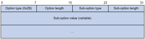
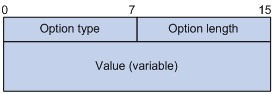
Network configuration parameters are carried in different sub-options of Option 43 as shown in Figure 5.
¡ Sub-option type—The field value can be 0x01 (an ACS parameter sub-option), 0x02 (a service provider identifier sub-option), or 0x80 (a PXE server address sub-option).
¡ Sub-option length—Excludes the sub-option type and sub-option length fields.
¡ Sub-option value—The value format varies with sub-options.
2. Sub-option value field formats:
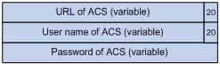
¡ ACS parameter sub-option value field—Contains variable ACS URL, username, and password separated by spaces (0x20) as shown in Figure 6.
Figure 6 ACS parameter sub-option value field
¡ Service provider identifier sub-option value field—Contains the service provider identifier.
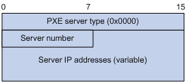
¡ PXE server address sub-option value field—Contains the PXE server type that can only be 0, the server number that indicates the number of PXE servers contained in the sub-option, and server IP addresses, as shown in Figure 7.
Figure 7 PXE server address sub-option value field
Relay agent option (Option 82)
Option 82 is the relay agent option in the option field of the DHCP message. It records the location information of the DHCP client. When a DHCP relay agent or DHCP snooping device receives a client's request, it adds Option 82 to the request message and sends it to the server.
The administrator can use Option 82 to locate the DHCP client and further implement security control and accounting. The DHCP server can use Option 82 to provide individual configuration policies for the clients.
Option 82 can contain up to 255 sub-options and must have at least one sub-option. The relay agent option 82 supports two sub-options: sub-option 1 (Circuit ID) and sub-option 2 (Remote ID). The DHCP snooping option 82 supports three sub-options: sub-option 1 (Circuit ID), sub-option 2 (Remote ID), and sub-option 9 (private padding format).
Option 82 has no standard definition. Its padding formats vary with vendors.
There are two methods for configuring Option 82:
· User-defined method—Manually specify the content of Option 82.
· Non-user-defined method—Pad Option 82 in the default normal format, verbose format, private format, or standard format.
|
|
NOTE: Only the DHCP snooping device supports sub-option 9, padded in either private or standard format. |
If you choose normal format or verbose format, you can specify the code type for the sub-options as ASCII or HEX.
· Normal padding format:
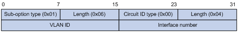
¡ Sub-option 1—Contains the VLAN ID and interface number of the interface that received the client's request. The value of the sub-option type is 1, and that of the circuit ID type is 0.
Figure 8 Sub-option 1 in normal padding format
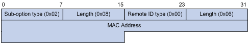
¡ Sub-option 2—Contains the MAC address of the DHCP relay agent interface or the MAC address of the DHCP snooping device that received the client's request. The value of the sub-option type is 2, and that of the remote ID type is 0.
Figure 9 Sub-option 2 in normal padding format
· Verbose padding format:
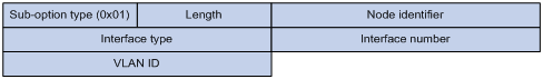
¡ Sub-option 1—Contains the user-specified access node identifier (ID of the device that adds Option 82 in DHCP messages), and the type, number, and VLAN ID of the interface that received the client's request. The VLAN ID field has a fixed length of 2 bytes. All the other padding contents of sub-option 1 are length variable. See Figure 10.
Figure 10 Sub-option 1 in verbose padding format
¡ Sub-option 2—Contains the MAC address of the DHCP relay agent interface or the MAC address of the DHCP snooping device that received the client's request. It has the same format as that in normal padding format. See Figure 9.
· Private padding format:
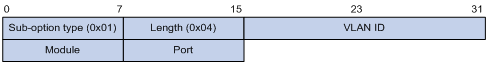
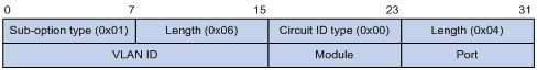
¡ Sub-option 1—Contains the VLAN ID of the interface that received the client's request, module, and port (number of the receiving port). The value of the sub-option type is 1.
Figure 11 Sub-option 1 in private padding format
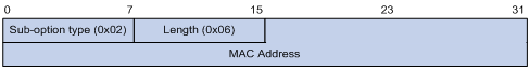
¡ Sub-option 2—Contains the MAC address of the DHCP snooping device that received the client's request. The value of the sub-option type is 2.
Figure 12 Sub-option 2 in private padding format
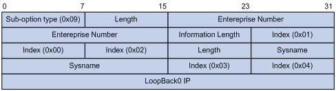
¡ Sub-option 9—Contains the sysname and the primary IP address of the Loopback0 interface. The value of the sub-option type is 9.
Figure 13 Sub-option 9 in private padding format
· Standard padding format:
¡ Sub-option 1—Contains the VLAN ID of the interface that received the client's request, module, and port (number of the receiving port). The value of the sub-option type is 1, and the value of the circuit ID type is 0.
Figure 14 Sub-option 1 in standard padding format
¡ Sub-option 2—Contains the MAC address of the DHCP snooping device that received the client's request. The value of the sub-option type is 2, and that of the remote ID type is 0. It has the same format as sub-option 2 in normal padding format. See Figure 9.
Option 184
Option 184 is a reserved option. You can define the parameters in the option as needed. The device supports Option 184 carrying voice related parameters, so a DHCP client with voice functions can get voice parameters from the DHCP server.
Option 184 has the following sub-options:
· Sub-option 1—Specifies the IP address of the primary network calling processor, which serves as the network calling control source and provides program download services.
· Sub-option 2—Specifies the IP address of the backup network calling processor. DHCP clients contact the backup processor when the primary one is unreachable.
· Sub-option 3—Specifies the voice VLAN ID and the result whether or not the DHCP clients takes this ID as the voice VLAN.
· Sub-option 4—Specifies the failover route that includes the IP address and the number of the target user. A Session Initiation Protocol (SIP) user uses this IP address and number to directly establish a connection to the target SIP user when both the primary and backup calling processors are unreachable.
For Option 184, you must define sub-option 1 to make other sub-options take effect.
Protocols and standards
· RFC 2131, Dynamic Host Configuration Protocol
· RFC 2132, DHCP Options and BOOTP Vendor Extensions
· RFC 1542, Clarifications and Extensions for the Bootstrap Protocol
· RFC 3046, DHCP Relay Agent Information Option
· RFC 3442, The Classless Static Route Option for Dynamic Host Configuration Protocol (DHCP) version 4
Overview
The DHCP server is well suited to networks where:
· Manual configuration and centralized management are difficult to implement.
· IP addresses are limited. For example, an ISP limits the number of concurrent online users, and most users must acquire IP addresses dynamically.
· Most hosts do not need fixed IP addresses.
DHCP address pool
DHCP address pools include common and extended address pools:
· Common address pool—Supports both static binding and dynamic allocation.
· Extended address pool—Supports only dynamic allocation.
Common address pool structure
The organization of the common address pool database can be compared to a tree. The root of the tree is the address pool for natural networks, branches are address pools for subnets, and leaves are addresses statically bound to clients. For the same level address pools, a previously configured pool has a higher selection priority than a new one.
At the very beginning, subnets inherit network parameters and clients inherit subnet parameters. Therefore, common parameters (for example, a DNS server address) should be configured at the highest (network or subnet) level of the tree.
The new configuration at the higher level (parent) of the tree is:
· Inherited if the lower level (child) has no such configuration.
IP address lease durations are not inherited.
· Overridden if the lower level (child) has such configuration.
|
|
NOTE: The extended address pools on a DHCP server are independent of each other, and no inheritance relationship exists among them. |
Principles for selecting an address pool
The DHCP server observes the following principles to select an address pool when assigning an IP address to a client:
1. If there is an address pool where an IP address is statically bound to the MAC address or ID of the client, the DHCP server selects this address pool and assigns the statically bound IP address to the client. For the configuration of this address pool, see "Configuring static address allocation."
2. If the receiving interface has an extended address pool referenced, the DHCP server assigns an IP address from this address pool. If no IP address is available in the address pool, the DHCP server fails to assign an address to the client. For the configuration of such an address pool, see "Configuring dynamic address allocation for an extended address pool."
3. Otherwise, the DHCP server selects the smallest common address pool that contains the IP address of the receiving interface (if the client and the server reside on the same subnet), or the smallest common address pool that contains the IP address specified in the giaddr field of the client's request (if a DHCP relay agent is in-between). If no IP address is available in the address pool, the DHCP server fails to assign an address to the client because it cannot assign an IP address from the parent address pool to the client. For the configuration of such an address pool, see "Configuring dynamic address allocation."
For example, two common address pools, 1.1.1.0/24 and 1.1.1.0/25, are configured on the DHCP server. If the IP address of the interface receiving DHCP requests is 1.1.1.1/25, the DHCP server selects IP addresses for clients from address pool 1.1.1.0/25. If no IP address is available in the address pool, the DHCP server fails to assign addresses to clients. If the IP address of the interface receiving DHCP requests is 1.1.1.130/25, the DHCP server selects IP addresses for clients from the 1.1.1.0/24 address pool.
|
|
NOTE: To avoid wrong IP address allocation, keep the IP addresses for dynamic allocation within the subnet where the interface of the DHCP server or DHCP relay agent resides. |
IP address allocation sequence
A DHCP server assigns an IP address to a client in the following sequence:
1. IP address statically bound to the client's MAC address or ID.
2. IP address that was ever assigned to the client.
3. IP address designated by the Option 50 field in a DHCP-DISCOVER message.
Option 50 is the requested IP address field in DHCP-DISCOVER messages. It is padded by the client to specify the IP address that the client wants to obtain. The contents to be padded depend on the client.
4. First assignable IP address found in an extended or common address pool.
5. IP address that was a conflict or passed its lease duration.
If no IP address is assignable, the server does not respond.
DHCP server configuration task list
|
Remarks |
|
|
Required. |
|
|
Required. |
|
|
Required. |
|
|
Required by the extended address pool configuration. When configuring a common address pool, ignore this task. |
|
|
Optional. |
|
|
Optional. |
|
|
Optional. |
|
|
Optional. |
Configuring an address pool on the DHCP server
Configuration task list
|
Task |
Remarks |
|
|
Required. |
||
|
Configuring address allocation mode for a common address pool |
Required to configure either of the two for the common address pool configuration. |
|
|
Configuring dynamic address allocation for an extended address pool |
Required for the extended address pool configuration. |
|
|
Optional. |
||
|
Configuring WINS servers and NetBIOS node type for the client |
||
|
Configuring Option 184 parameters for the client with voice service |
||
|
Configuring the TFTP server and bootfile name for the client |
||
Creating a DHCP address pool
When you create a DHCP address pool, specify it as a common address pool or an extended address pool.
To create a DHCP address pool:
|
Step |
Command |
Remarks |
|
1. Enter system view. |
system-view |
N/A |
|
2. Create a DHCP address pool and enter its view. |
dhcp server ip-pool pool-name [ extended ] |
No DHCP address pool is created by default. |
A common address pool and an extended address pool are different in address allocation mode configuration. Configurations of other parameters (such as the domain name suffix and DNS server address) for them are the same.
Configuring address allocation mode for a common address pool
|
|
CAUTION: You can configure either a static binding or dynamic address allocation for a common address pool, but not both. |
You need to specify a subnet for dynamic address allocation. A static binding is a special address pool containing only one IP address.
Configuring static address allocation
Some DHCP clients, such as a WWW server, need fixed IP addresses. To provide a fixed IP address for such a client, you can statically bind the MAC address or ID of the client to an IP address in a DHCP address pool. When the client requests an IP address, the DHCP server assigns the IP address in the static binding to the client.
Follow these guidelines when you configure static address allocation:
· Use the static-bind ip-address command together with static-bind mac-address or static-bind client-identifier to accomplish a static binding configuration.
· In a DHCP address pool, if you execute the static-bind mac-address command before the static-bind client-identifier command, the latter overwrites the former and vice versa.
· If you use the static-bind ip-address, static-bind mac-address, or static-bind client-identifier command repeatedly in the DHCP address pool, the new configuration overwrites the previous one.
· The IP address of the static binding cannot be an interface address of the DHCP server. Otherwise, an IP address conflict may occur, making the bound client unable to obtain an IP address correctly.
· The ID of the static binding must be identical to the ID displayed by using the display dhcp client verbose command on the client. Otherwise, the client cannot obtain an IP address.
· The specified lease duration takes effect but the lease duration displayed by the display dhcp server ip-in-use all command is still Unlimited.
· When the device serves as a DHCP client or BOOTP client, you must bind the DHCP client's ID to an IP address, or bind the BOOTP client's MAC address to an IP address on the DHCP server. Otherwise, the DHCP or BOOTP client cannot obtain a static IP address.
· If the interfaces on a DHCP client share the same MAC address, specify the client ID, rather than MAC address, in a static binding to identify the requesting interface. If you do not do this, the client may fail to obtain an IP address.
To configure a static binding in a common address pool:
|
Step |
Command |
Remarks |
|
1. Enter system view. |
system-view |
N/A |
|
2. Enter common address pool view. |
dhcp server ip-pool pool-name |
N/A |
|
3. Specify the IP address. |
static-bind ip-address ip-address [ mask-length | mask mask ] |
No IP addresses are statically bound by default. |
|
4. Specify the MAC address or client ID. |
·
Specify the MAC address: ·
Specify the client ID: |
Use either of the commands. Neither is bound statically by default. |
|
5. Specify the lease duration for the IP address. |
expired { day day [ hour hour [ minute minute [ second second ] ] ] | unlimited } |
Optional. By default, the lease duration of the IP address is unlimited. |
Configuring dynamic address allocation
For dynamic address allocation, you must configure a DHCP address pool, specify one and only one address range for the pool, and specify the lease duration. A DHCP address pool can have only one lease duration.
To avoid address conflicts, configure the DHCP server to exclude IP addresses used by the gateway or FTP server from dynamic allocation.
Follow these guidelines when you configure dynamic address allocation:
· In common address pool view, using the network or network ip range command repeatedly overwrites the previous configuration.
· After you exclude IP addresses from automatic allocation by using the dhcp server forbidden-ip command, neither a common address pool nor an extended address pool can assign these IP addresses through dynamic address allocation.
· Using the dhcp server forbidden-ip command repeatedly can exclude multiple IP address ranges from allocation.
To configure dynamic address allocation for a common address pool:
|
Step |
Command |
Remarks |
|
1. Enter system view. |
system-view |
N/A |
|
2. Enter common address pool view. |
dhcp server ip-pool pool-name |
N/A |
|
3. Specify a subnet. |
network network-address [ mask-length | mask mask ] |
Not specified by default. |
|
4. Specify the IP address range on the subnet for dynamic allocation. |
network ip range min-address max-address |
Optional. Not specified by default. |
|
5. Specify the address lease duration. |
expired { day day [ hour hour [ minute minute ] [ second second ] ] | unlimited } |
Optional. One day by default. |
|
6. Return to system view. |
quit |
N/A |
|
7. Exclude IP addresses from automatic allocation. |
dhcp server forbidden-ip low-ip-address [ high-ip-address ] |
Optional. Except IP addresses of the DHCP server interfaces, all addresses in the DHCP address pool are assignable by default. |
Configuring dynamic address allocation for an extended address pool
Extended address pools support dynamic address allocation only.
When configuring an extended address pool, you must specify:
· Assignable IP address range
· Mask
After the assignable IP address range and the mask are specified, the address pool becomes valid.
To configure dynamic address allocation for an extended address pool:
|
Step |
Command |
Remarks |
|
1. Enter system view. |
system-view |
N/A |
|
2. Enter extended address pool view. |
dhcp server ip-pool pool-name extended |
N/A |
|
3. Specify the IP address range. |
network ip range min-address max-address |
Not specified by default. |
|
4. Specify the IP address mask. |
network mask mask |
Not specified by default. |
|
5. Specify the IP address range for the DHCP clients of a specified vendor. |
vendor-class-identifier hex-string&<1-255> ip range min-address max-address |
Optional. Not configured by default. |
|
6. Specify the address lease duration. |
expired { day day [ hour hour [ minute minute [ second second ] ] ] | unlimited } |
Optional. One day by default. |
|
7. Exclude IP addresses from dynamic allocation. |
forbidden-ip ip-address&<1-8> |
Optional. Except IP addresses of the DHCP server interfaces, all addresses in the DHCP address pool are assignable by default. |
Excluded IP addresses specified with the forbidden-ip command in DHCP address pool view are not assignable in the current extended address pool, but are assignable in other address pools.
Configuring a domain name suffix for the client
You can specify a domain name suffix in each DHCP address pool on the DHCP server to provide the clients with the domain name suffix. With this suffix assigned, the client only needs to input part of a domain name, and the system adds the domain name suffix for name resolution. For more information about DNS, see "Configuring IPv4 DNS."
To configure a domain name suffix in the DHCP address pool:
|
Step |
Command |
Remarks |
|
1. Enter system view. |
system-view |
N/A |
|
2. Enter DHCP address pool view. |
dhcp server ip-pool pool-name [ extended ] |
N/A |
|
3. Specify a domain name suffix. |
domain-name domain-name |
Not specified by default. |
Configuring DNS servers for the client
To access hosts on the Internet through domain names, a DHCP client must contact a DNS server to resolve names. You can specify up to eight DNS servers in a DHCP address pool.
To configure DNS servers in a DHCP address pool:
|
Step |
Command |
Remarks |
|
1. Enter system view. |
system-view |
N/A |
|
2. Enter DHCP address pool view. |
dhcp server ip-pool pool-name [ extended ] |
N/A |
|
3. Specify DNS servers. |
dns-list ip-address&<1-8> |
No DNS server is specified by default. |
Configuring WINS servers and NetBIOS node type for the client
A Microsoft DHCP client using NetBIOS protocol must contact a Windows Internet Naming Service (WINS) server for name resolution. You can specify up to eight WINS servers for such clients in a DHCP address pool.
Specify a NetBIOS node type for the clients to approach name resolution. There are four NetBIOS node types:
· b (broadcast)-node—A b-node client sends the destination name in a broadcast message. The destination returns its IP address to the client after receiving the message.
· p (peer-to-peer)-node—A p-node client sends the destination name in a unicast message to the WINS server, and the WINS server returns the destination IP address.
· m (mixed)-node—An m-node client broadcasts the destination name. If it receives no response, it unicasts the destination name to the WINS server to get the destination IP address.
· h (hybrid)-node—An h-node client unicasts the destination name to the WINS server. If it receives no response, it broadcasts the destination name to get the destination IP address.
To configure WINS servers and NetBIOS node type in a DHCP address pool:
|
Step |
Command |
Remarks |
|
1. Enter system view. |
system-view |
N/A |
|
2. Enter DHCP address pool view. |
dhcp server ip-pool pool-name [ extended ] |
N/A |
|
3. Specify WINS servers. |
nbns-list ip-address&<1-8> |
Optional for b-node. No WINS server is specified by default. |
|
4. Specify the NetBIOS node type. |
netbios-type { b-node | h-node | m-node | p-node } |
Not specified by default. |
Configuring BIMS server information for the client
Perform this task to provide the Branch Intelligent Management System (BIMS) server IP address, port number, and shared key for the clients. The DHCP clients contact the BIMS server to get configuration files and perform software update and backup.
To configure the BIMS server IP address, port number, and shared key in the DHCP address pool:
|
Step |
Command |
Remarks |
|
1. Enter system view. |
system-view |
N/A |
|
2. Enter DHCP address pool view. |
dhcp server ip-pool pool-name [ extended ] |
N/A |
|
3. Specify the BIMS server IP address, port number, and shared key. |
bims-server ip ip-address [ port port-number ] sharekey [ cipher | simple ] key |
No BIMS server information is specified by default. |
Configuring gateways for the client
|
Step |
Command |
Remarks |
|
1. Enter system view. |
system-view |
N/A |
|
2. Enter DHCP address pool view. |
dhcp server ip-pool pool-name [ extended ] |
N/A |
|
3. Specify gateways. |
gateway-list ip-address&<1-8> |
No gateway is specified by default. You can specify up to eight gateways in a DHCP address pool. |
Configuring Option 184 parameters for the client with voice service
To assign calling parameters to DHCP clients with voice service, you must configure Option 184 on the DHCP server. For more information about Option 184, see "DHCP overview."
To configure option 184 parameters in a DHCP address pool:
|
Step |
Command |
Remarks |
|
1. Enter system view. |
system-view |
N/A |
|
2. Enter DHCP address pool view. |
dhcp server ip-pool pool-name [ extended ] |
N/A |
|
3. Specify the IP address of the network calling processor. |
voice-config ncp-ip ip-address |
No network calling processor is specified by default. Specify an IP address for the network calling processor before performing other configurations. |
|
4. Specify the IP address of the backup network calling processor. |
voice-config as-ip ip-address |
Optional. No backup network calling processor is specified by default. |
|
5. Configure the voice VLAN. |
voice-config voice-vlan vlan-id { disable | enable } |
Optional. No voice VLAN is configured by default. |
|
6. Specify the failover IP address and dialer string. |
voice-config fail-over ip-address dialer-string |
Optional. No failover IP address or dialer string is specified by default. |
Configuring the TFTP server and bootfile name for the client
For the DHCP server to support client auto-configuration, specify the IP address or name of a TFTP server and the bootfile name in the DHCP address pool. You do not need to perform any configuration on the DHCP client.
The DHCP client obtains these parameters from the DHCP server, and uses them to contact the TFTP server to request the configuration file used for system initialization.
1. When a router starts up without loading any configuration file, the system sets an active interface (such as the interface of the default VLAN or a Layer 3 Ethernet interface) as the DHCP client to request from the DHCP server for parameters, such as an IP address and name of a TFTP server, and the bootfile name.
2. After receiving related parameters, the DHCP client sends a TFTP request to obtain the configuration file from the specified TFTP server for system initialization. If the client cannot get such parameters, it performs system initialization without loading any configuration file.
To configure the IP address and name of the TFTP server and the bootfile name in the DHCP address pool:
|
Step |
Command |
Remarks |
|
1. Enter system view. |
system-view |
N/A |
|
2. Enter DHCP address pool view. |
dhcp server ip-pool pool-name [ extended ] |
N/A |
|
3. Specify the IP address or the name of the TFTP server. |
·
Specify the TFTP server: ·
Specify the name of the TFTP server: |
Use either command. Not specified by default. |
|
4. Specify the bootfile name. |
bootfile-name bootfile-name |
Not specified by default. |
Specifying a server's IP address for the DHCP client
Some DHCP clients need to obtain configuration information from a server, such as a TFTP server. You can specify the IP address of that server in each address pool of the DHCP server. The DHCP server sends the server's IP address to DHCP clients along with other configuration information.
To specify the IP address of a server:
|
Step |
Command |
Remarks |
|
1. Enter system view. |
system-view |
N/A |
|
2. Enter DHCP address pool view. |
dhcp server ip-pool pool-name [ extended ] |
N/A |
|
3. Specify the IP address of a server. |
next-server ip-address |
Not specified by default. |
Configuring self-defined DHCP options
|
|
CAUTION: Be careful when configuring self-defined DHCP options because such configuration may affect DHCP operation. |
By configuring self-defined DHCP options, you can
· Define new DHCP options. New configuration options come out with DHCP development. To support these new options, you can add them into the attribute list of the DHCP server.
· Define existing DHCP options. Vendors use Option 43 to define options that have no unified definitions in RFC 2132. The self-defined DHCP option enables DHCP clients to obtain vendor-specific information.
· Extend existing DHCP options. When the current DHCP options cannot meet the customers' requirements (for example, you cannot use the dns-list command to configure more than eight DNS server addresses), you can configure a self-defined option for extension.
To configure a self-defined DHCP option in a DHCP address pool:
|
Step |
Command |
Remarks |
|
1. Enter system view. |
system-view |
N/A |
|
2. Enter DHCP address pool view. |
dhcp server ip-pool pool-name [ extended ] |
N/A |
|
3. Configure a self-defined DHCP option. |
option code { ascii ascii-string | hex hex-string&<1-16> | ip-address ip-address&<1-8> } |
No self-defined DHCP option is configured by default. |
See Table 1 for a description of common options and corresponding commands.
|
Option |
Option name |
Corresponding command |
Command parameter |
|
3 |
Router Option |
gateway-list |
ip-address |
|
6 |
Domain Name Server Option |
dns-list |
ip-address |
|
15 |
Domain Name |
domain-name |
ascii |
|
44 |
NetBIOS over TCP/IP Name Server Option |
nbns-list |
ip-address |
|
46 |
NetBIOS over TCP/IP Node Type Option |
netbios-type |
hex |
|
66 |
TFTP server name |
tftp-server |
ascii |
|
67 |
Bootfile name |
bootfile-name |
ascii |
|
43 |
Vendor Specific Information |
N/A |
hex |
Enabling DHCP
Enable DHCP to validate other DHCP configurations.
To enable DHCP:
|
Step |
Command |
Remarks |
|
1. Enter system view. |
system-view |
N/A |
|
2. Enable DHCP. |
dhcp enable |
The default setting is disabled by default. |
Enabling the DHCP server on an interface
Perform this task to enable the DHCP server on an interface. Upon receiving a DHCP request on the interface, the DHCP server assigns an IP address and other configuration parameters from the DHCP address pool to the DHCP client.
Configuration guidelines
Follow these guidelines when you enable the DHCP server on an interface:
· If a DHCP relay agent exists between the DHCP server and client, the DHCP server, regardless of whether the subaddress keyword is used, selects an IP address from the address pool containing the primary IP address of the DHCP relay agent's interface (connected to the client) for a requesting client.
· When the DHCP server and client are on the same subnet:
¡ With the keyword subaddress specified, the DHCP server preferably assigns an IP address from an address pool that resides on the same subnet as the primary IP address of the server interface (connecting to the client). If the address pool contains no assignable IP address, the server assigns an IP address from an address pool that resides on the same subnet as the secondary IP addresses of the server interface. If the interface has multiple secondary IP addresses, each address pool is tried in turn for address allocation.
¡ Without the keyword subaddress specified, the DHCP server can only assign an IP address from the address pool that resides on the same subnet as the primary IP address of the server interface.
Configuration procedure
To enable the DHCP server on an interface:
|
Step |
Command |
Remarks |
|
1. Enter system view. |
system-view |
N/A |
|
2. Enter interface view. |
interface interface-type interface-number |
N/A |
|
3. Enable the DHCP server on the interface. |
dhcp select server global-pool [ subaddress ] |
Optional. The default setting is enabled by default. |
Applying an extended address pool on an interface
After you create an extended address pool and apply it on an interface, a DHCP server, upon receiving a client's request on the interface, attempts to assign the client the statically bound IP address first and then an IP address from the specified address pool. If no IP address is available in this address pool, address allocation fails, and the DHCP server does not assign the client any IP address from other address pools.
Only an extended address pool can be applied on the interface. The address pool to be referenced must already exist.
To apply an extended address pool on an interface:
|
Step |
Command |
Remarks |
|
1. Enter system view. |
system-view |
N/A |
|
2. Enter interface view. |
interface interface-type interface-number |
N/A |
|
3. Apply an extended address pool on the interface. |
dhcp server apply ip-pool pool-name |
Optional. By default, the DHCP server has no extended address pool applied on its interface, and assigns an IP address from a common address pool to a requesting client. |
Configuring the DHCP server security functions
Configuration prerequisites
Before you perform this configuration, complete the following configurations on the DHCP server:
1. Enable DHCP.
2. Configure the DHCP address pool.
Enabling unauthorized DHCP server detection
Unauthorized DHCP servers on a network may assign wrong IP addresses to DHCP clients.
With unauthorized DHCP server detection enabled, the DHCP server checks whether a DHCP request contains Option 54 (Server Identifier Option). If yes, the DHCP server records in the option the IP address of the DHCP server that assigned an IP address to a requesting DHCP client and records the receiving interface. The administrator can use this information to check for unauthorized DHCP servers.
To enable unauthorized DHCP server detection:
|
Step |
Command |
Remarks |
|
1. Enter system view. |
system-view |
N/A |
|
2. Enable unauthorized DHCP server detection. |
dhcp server detect |
Disabled by default. |
With the unauthorized DHCP server detection enabled, the device logs each detected DHCP server once. The administrator can use the log information to find unauthorized DHCP servers.
Configuring IP address conflict detection
Before assigning an IP address, the DHCP server pings that IP address.
· If the server receives a response within the specified period, it selects and pings another IP address.
· If it receives no response, the server continues to ping the IP address until a specified number of ping packets are sent. If still no response is received, the server assigns the IP address to the requesting client. (The DHCP client probes the IP address by sending gratuitous ARP packets.)
To configure IP address conflict detection:
|
Step |
Command |
Remarks |
|
1. Enter system view. |
system-view |
N/A |
|
2. Specify the maximum number of ping packets to be sent for conflict detection. |
dhcp server ping packets number |
Optional. The default setting is one. The value 0 disables IP address conflict detection. |
|
3. Configure the ping timeout time. |
dhcp server ping timeout milliseconds |
Optional. The default setting is 500 ms. The value 0 disables IP address conflict detection. |
Enabling client offline detection
With this feature enabled, the DHCP server considers that a DHCP client goes offline when the ARP entry for the client ages out. In addition, it removes the client's IP-to-MAC binding entry and releases the IP address of the client. Removing an ARP entry manually does not remove the corresponding client's IP-to-MAC binding.
To enable offline detection:
|
Step |
Command |
Remarks |
|
1. Enter system view. |
system-view |
N/A |
|
2. Enter interface view. |
interface interface-type interface-number |
N/A |
|
3. Enable offline detection. |
dhcp server client-detect enable |
Disabled by default. |
Enabling handling of Option 82
If the server is configured to ignore Option 82, it assigns an IP address to the client without adding Option 82 in the response message.
Configuration prerequisites
Before you perform this configuration, complete the following configurations on the DHCP server:
1. Enable DHCP.
2. Configure the DHCP address pool.
Enabling Option 82 handling
To enable the DHCP server to handle Option 82:
|
Step |
Command |
Remarks |
|
1. Enter system view. |
system-view |
N/A |
|
2. Enable the server to handle Option 82. |
dhcp server relay information enable |
Optional. Enabled by default. |
To support Option 82 requires configuring both the DHCP server and relay agent (or the device enabled with DHCP snooping).
Specifying the threshold for sending trap messages
Configuration prerequisites
Before you perform the configuration, use the snmp-agent target-host command to specify the destination address of the trap messages. For more information about the command, see Network Management and Monitoring Command Reference.
Configuration procedure
A DHCP server sends trap messages to the network management server when one of the following items reaches the specified threshold:
· The ratio of successfully allocated IP addresses to received DHCP requests
· The average IP address utilization of the address pool
· The maximum IP address utilization of the address pool
· The ratio of successfully allocated IP addresses in an address pool
Trap messages help network administrators know the latest usage information of the DHCP server.
To specify the threshold for sending trap messages:
|
Step |
Command |
Remarks |
|
1. Enter system view. |
system-view |
N/A |
|
2. Specify the threshold for sending trap messages to the network management server. |
dhcp server threshold { allocated-ip threshold-value | average-ip-use threshold-value | max-ip-use threshold-value | success-rate threshold-value } |
Optional. Disabled by default. |
Displaying and maintaining the DHCP server
|
|
NOTE: A restart of the DHCP server or execution of the reset dhcp server ip-in-use command deletes all lease information. The DHCP server denies any DHCP request for lease extension, and the client must request an IP address again. |
|
Task |
Command |
Remarks |
|
Display information about IP address conflicts. |
display dhcp server conflict { all | ip ip-address } [ | { begin | exclude | include } regular-expression ] |
Available in any view. |
|
Display information about lease expiration. |
display dhcp server expired { all | ip ip-address | pool [ pool-name ] } [ | { begin | exclude | include } regular-expression ] |
Available in any view. |
|
Display information about assignable IP addresses. |
display dhcp server free-ip [ | { begin | exclude | include } regular-expression ] |
Available in any view. |
|
Display IP addresses excluded from automatic allocation in the DHCP address pool. |
display dhcp server forbidden-ip [ | { begin | exclude | include } regular-expression ] |
Available in any view. |
|
Display information about bindings. |
display dhcp server ip-in-use { all | ip ip-address | pool [ pool-name ] } [ | { begin | exclude | include } regular-expression ] |
Available in any view. |
|
Display information about DHCP server statistics. |
display dhcp server statistics [ | { begin | exclude | include } regular-expression ] |
Available in any view. |
|
Display tree organization information of address pools. |
display dhcp server tree { all | pool [ pool-name ] } [ | { begin | exclude | include } regular-expression ] |
Available in any view. |
|
Clear information about IP address conflicts. |
reset dhcp server conflict { all | ip ip-address } |
Available in user view. |
|
Clear information about dynamic bindings. |
reset dhcp server ip-in-use { all | ip ip-address | pool [ pool-name ] } |
Available in user view. |
|
Clear information about DHCP server statistics. |
reset dhcp server statistics |
Available in user view. |
DHCP server configuration examples
DHCP networking involves two types:
· The DHCP server and client are on the same subnet and exchange messages directly.
· The DHCP server and client are not on the same subnet and they communicate with each other via a DHCP relay agent.
The DHCP server configuration for the two types is the same.
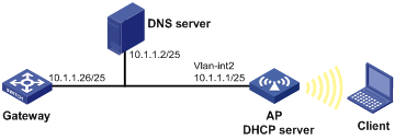
Static IP address assignment configuration example
Network requirements
As shown in Figure 15, Wireless client (DHCP client) obtains a static IP address, DNS server address, and gateway address from AP (DHCP server).
Configuration procedure
1. Configure the wireless service on the fat AP:
# Create a WLAN BSS interface.
<AP> system-view
[AP] interface WLAN-BSS 1
[AP-WLAN-BSS1] quit
# Configure a clear type WLAN service template that adopts open-system authentication, and enable the template.
[AP] wlan service-template 1 clear
[AP-wlan-st-1] ssid service
[AP-wlan-st-1] authentication-method open-system
[AP-wlan-st-1] service-template enable
[AP-wlan-st-1]quit
# Bind WLAN-Radio 1/0/1 to service template 1 and WLAN-BSS 1.
[AP] interface WLAN-Radio 1/0/1
[AP-WLAN-Radio1/0/1] radio-type dot11an
[AP-WLAN-Radio1/0/1] service-template 1 interface WLAN-BSS 1
[AP-WLAN-Radio1/0/1] quit
# Assign WLAN-BSS1 to VLAN 2.
[AP] interface WLAN-BSS 1
[AP-WLAN-BSS1] port access vlan 2
[AP-WLAN-BSS1] quit
2. Configure the IP address of VLAN-interface 2 on Switch A.
[AP] interface vlan-interface 2
[AP-Vlan-interface2] ip address 10.1.1.1 25
[AP-Vlan-interface2] quit
3. Configure the DHCP server:
# Enable DHCP.
[AP] dhcp enable
# Create DHCP address pool 0, configure a static IP-MAC binding, DNS server and gateway in it.
[AP] dhcp server ip-pool 0
[AP-dhcp-pool-0] static-bind ip-address 10.1.1.5 25
[AP-dhcp-pool-0] static-bind mac-address 000f-e200-0002
[AP-dhcp-pool-0] dns-list 10.1.1.2
[AP-dhcp-pool-0] gateway-list 10.1.1.26
[AP-dhcp-pool-0] quit
You can view the detailed information, such as IP address, DHCP server, and DNS server, about the client when the client goes online.
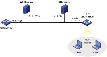
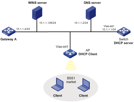
Dynamic IP address assignment configuration example
Network requirements
· As shown in Figure 16, the DHCP server (AP) assigns IP address to clients in subnet 10.1.1.0/24, which is subnetted into 10.1.1.0/25 and 10.1.1.128/25.
· The IP addresses of VLAN-interfaces 1 and 2 on AP are 10.1.1.1/25 and 10.1.1.129/25 respectively.
· In address pool 10.1.1.0/25, the address lease duration is ten days and twelve hours, domain name suffix is aabbcc.com, DNS server address is 10.1.1.2/25, gateway address is 10.1.1.126/25, and WINS server address is 10.1.1.4/25.
· In address pool 10.1.1.128/25, the address lease duration is five days, domain name suffix is aabbcc.com, DNS server address is 10.1.1.2/25, gateway address is 10.1.1.254/25, and there is no WINS server address.
· The domain name and DNS server address on subnets 10.1.1.0/25 and 10.1.1.128/25 are the same. Therefore, the domain name suffix and DNS server address can be configured only for subnet 10.1.1.0/24. Subnet 10.1.1.128/25 can inherit the configuration of subnet 10.1.1.0/24.
|
|
NOTE: In this example, the number of requesting clients connected to VLAN-interface 1 should be less than 122, and that of clients connected to VLAN-interface 2 less than 124. |
Configuration procedure
1. Create two WLAN services (market and management), and add the corresponding WLAN-BSS interfaces (WLAN-BSS1 and WLAN-BSS2) into VLAN 1 and VLAN 2 respectively. (For more information, see "Configure the wireless service on the fat AP:.")
2. Specify IP addresses for VLAN interfaces. (Details not shown.)
3. Configure the DHCP server:
# Enable DHCP.
<AP> system-view
[AP] dhcp enable
# Exclude IP addresses (addresses of the DNS server, WINS server, and gateways).
[AP] dhcp server forbidden-ip 10.1.1.2
[AP] dhcp server forbidden-ip 10.1.1.4
[AP] dhcp server forbidden-ip 10.1.1.126
# Configure DHCP address pool 0 (address range, client domain name suffix, and DNS server address).
[AP] dhcp server ip-pool 0
[AP-dhcp-pool-0] network 10.1.1.0 mask 255.255.255.0
[AP-dhcp-pool-0] domain-name aabbcc.com
[AP-dhcp-pool-0] dns-list 10.1.1.2
[AP-dhcp-pool-1] gateway-list 10.1.1.4
[AP-dhcp-pool-1] expired day 10 hour 12
[AP-dhcp-pool-1] nbns-list 10.1.1.126
[AP-dhcp-pool-0] quit
You can view the detailed information, such as IP address, DHCP server, DNS server, and WIN server about the client when the client goes online.
Self-defined option configuration example
Network requirements
· As shown in Figure 17, the DHCP client (Switch) obtains an IP address and PXE server addresses from the DHCP server (AP).
· The IP address that Switch obtains belongs to network segment 10.1.1.0/24.
· The PXE server addresses that Switch obtains are 1.2.3.4 and 2.2.2.2.
· The DHCP server assigns PXE server addresses to DHCP clients through Option 43, a self-defined option. The format of Option 43 and that of the PXE server address sub-option are shown in Figure 5 and Figure 7, respectively. The value of Option 43 configured on the DHCP server in this example is 80 0B 00 00 02 01 02 03 04 02 02 02 02. The number 80 is the value of the sub-option type. The number 0B is the value of the sub-option length. The numbers 00 00 are the value of the PXE server type. The number 02 indicates the number of servers. The numbers 01 02 03 04 02 02 02 02 indicate that the PXE server addresses are 1.2.3.4 and 2.2.2.2.
Configuration procedure
1. Specify IP addresses for the interfaces. (Details not shown.)
2. Configure the DHCP server:
# Enable DHCP.
<AP> system-view
[AP] dhcp enable
# Configure DHCP address pool 0.
[AP] dhcp server ip-pool 0
[AP-dhcp-pool-0] network 10.1.1.0 mask 255.255.255.0
[AP-dhcp-pool-0] option 43 hex 80 0B 00 00 02 01 02 03 04 02 02 02 02
Troubleshooting DHCP server configuration
Symptom
A client's IP address obtained from the DHCP server conflicts with another IP address.
Analysis
Another host on the subnet may have the same IP address.
Solution
1. Disable the client's network adapter or disconnect the client's network cable. Ping the IP address of the client from another host to check whether there is a host using the same IP address.
2. If a ping response is received, the IP address has been manually configured on a host. Execute the dhcp server forbidden-ip command on the DHCP server to exclude the IP address from dynamic allocation.
3. Enable the network adapter or connect the network cable. Release the IP address and obtain another one on the client. For example, to release the IP address and obtain another one on a Windows XP DHCP client:
a. In Windows environment, select Start > Run.
b. Enter cmd in the dialog box, and click OK to enter the command line interface.
c. Enter ipconfig/release to relinquish the IP address.
d. Enter ipconfig/renew to obtain another IP address.
The DHCP client configuration is supported only on VLAN interfaces.
You cannot configure an interface of an aggregation group as a DHCP client.
When multiple VLAN interfaces with the same MAC address use DHCP for IP address acquisition through a relay agent, the DHCP server cannot be a Windows Server 2000 or Windows Server 2003.
Introduction to DHCP client
With DHCP client enabled, an interface uses DHCP to obtain configuration parameters such as an IP address from the DHCP server.
Enabling the DHCP client on an interface
To enable the DHCP client on an interface:
|
Step |
Command |
Remarks |
|
1. Enter system view. |
system-view |
N/A |
|
2. Enter interface view. |
interface interface-type interface-number |
N/A |
|
3. Enable the DHCP client on the interface. |
ip address dhcp-alloc [ client-identifier mac interface-type interface-number ] |
Disabled by default. |
An interface can be configured to acquire an IP address in multiple ways. The latest configuration overwrites the previous one.
Secondary IP addresses cannot be configured on an interface that is enabled with the DHCP client.
If the IP address that interface A obtains from the DHCP server is on the same network segment as the IP address of interface B, interface A neither uses the IP address nor requests any IP address from the DHCP server, unless the IP address of interface B is manually deleted and interface A is brought up again by first executing the shutdown command and then the undo shutdown command or the DHCP client is re-enabled on interface A by executing the undo ip address dhcp-alloc command and then the ip address dhcp-alloc command.
Displaying and maintaining the DHCP client
|
Task |
Command |
Remarks |
|
Display specified configuration information. |
display dhcp client [ verbose ] [ interface interface-type interface-number ] [ | { begin | exclude | include } regular-expression ] |
Available in any view. |
DHCP client configuration example
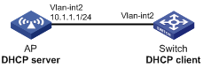
Network requirements
As shown in Figure 18, the AP's interface belongs to VLAN 1 and connects to the LAN. VLAN-interface 1 obtains its IP address through DHCP.
Configuration procedure
This example only describes the configuration of the AP serving as the DHCP client.
# Enable the DHCP client on VLAN-interface 1.
<AP> system-view
[AP] interface vlan-interface 1
[AP-Vlan-interface1] ip address dhcp-alloc
Use the display dhcp client command to view the IP address and other network parameters assigned to the AP.
|
|
NOTE: To enable the DHCP client to obtain an IP address from the DHCP server, you must make configurations on the DHCP server. For more information, see "DHCP server configuration examples." |