- Table of Contents
- Related Documents
-
| Title | Size | Download |
|---|---|---|
| 02-Installing the device | 2.30 MB |
Contents
Confirming installation preparations
Mounting the device on a workbench
Installing the device in a 19-inch rack
Installing the device by using front and rear mounting brackets
Installing the device by using front mounting brackets and a rack shelf
Installing the device by using front mounting brackets and slide rails
Installing optional components
Installing a lightning arrester for a network port
Installing a lightning arrester for an AC power module
Connecting the console cable and setting terminal parameters
Connecting the Ethernet cables
Connecting a copper Ethernet port
Installing the device
|
|
WARNING! Keep the tamper-proof seal on a mounting screw on the chassis cover intact, and if you want to open the chassis, contact H3C Support for permission. Otherwise, H3C will not be liable for any consequence caused thereby. |
Confirming installation preparations
Before you install the device, verify that you have read "Preparing for installation" carefully and the installation site meets all the requirements.
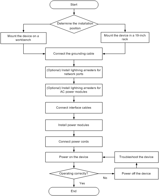
Installation flow
Mounting the device on a workbench
|
|
CAUTION: Do not place heavy objects on the device. |
If a standard 19-inch rack is not available, you can mount the device on a clean, flat workbench.
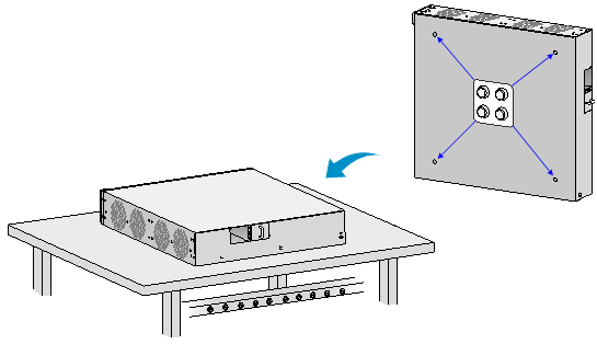
To mount the device on a workbench:
1. Place the device upside down. Clean the recessed areas in the chassis bottom.
2. Attach the four rubber feet to the recessed areas in the chassis bottom.
3. Place the device on the workbench with the upside up.
Figure 2 Mounting the device on a workbench
Installing the device in a 19-inch rack
You can install the device in a 19-inch rack by using the following methods:
· Installing the device by using front and rear mounting brackets.
· Installing the device by using front mounting brackets and a rack shelf.
· Installing the device by using front mounting brackets and slide rails.
Mounting brackets
Figure 3 Front mounting bracket
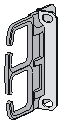
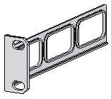
Figure 4 Rear mounting bracket
Installing the device by using front and rear mounting brackets
1. Wear an ESD wrist strap and make sure the rack is sturdy and is reliably grounded.
2. Use a front mounting bracket to mark the cage nut installation position on the front rack posts. Install cage nuts.
Figure 5 Installing cage nuts
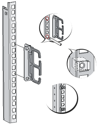
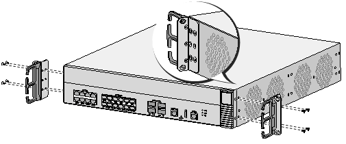
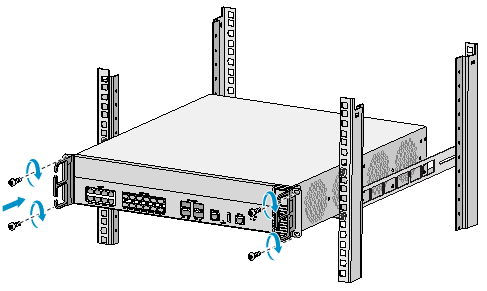
3. Use the screws supplied with the front mounting brackets to attach the front mounting brackets to both sides of the device.
Figure 6 Attaching the front mounting brackets to the device
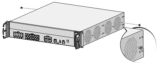
4. Attach the load-bearing screws supplied with the rear mounting brackets to both sides of the device.
The load-bearing screws will be in close touch with the rear mounting brackets to support the device.
Figure 7 Installing the load-bearing screws
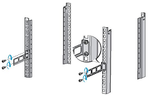
5. According to the device installation position in the rack, use screws and cage nuts to attach the rear mounting brackets to the rear rack posts.
Figure 8 Installing rear mounting brackets
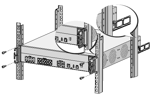
6. Supporting the bottom of the device with one hand and holding the front of the device with the other, place the device slowly in the rack. Attach the front mounting brackets on the device to the front rack posts with screws and cage nuts, as shown in Figure 9. Make sure the load-bearing screws are in close contact with the upper edges of the rear mounting brackets.
Figure 9 Installing the device in the rack
Installing the device by using front mounting brackets and a rack shelf
The rack shelf is an optional component that needs to be separately ordered if needed. The rack shelf in this example is for illustration only.
To install the device by using front mounting brackets and a rack shelf:
1. Wear the ESD wrist strap and verify that the rack is sturdy and is reliably grounded.
2. Use the screws supplied with the front mounting brackets to attach the front mounting brackets to the device, as shown in Figure 6.
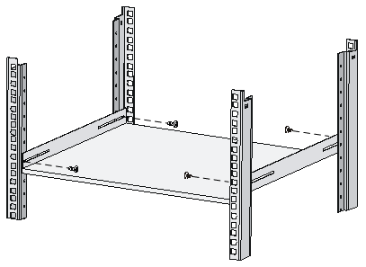
3. Attach the rack shelf to the desired position in the rack. See Figure 10 for reference.
Figure 10 Installing the rack shelf
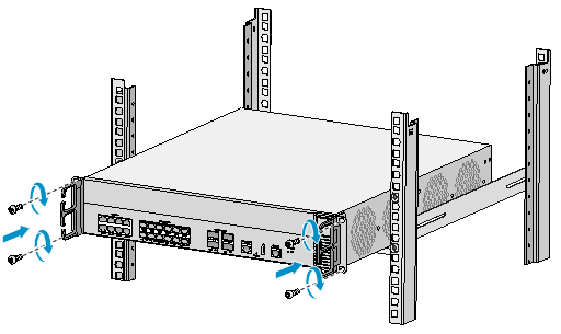
4. Place the device on the rack shelf and push the device in the rack. Attach the front mounting brackets on the device to the front rack posts by using screws and cage nuts, as shown in Figure 11.
Figure 11 Installing the device in the rack
Installing the device by using front mounting brackets and slide rails
The slide rails are optional components that need to be separately ordered if needed. The slide rails in this example are for illustration only.
To install the device by using front mounting brackets and slide rails:
1. Wear the ESD wrist strap and verify that the rack is sturdy and is reliably grounded.
2. Use the screws supplied with the front mounting brackets to attach the front mounting brackets to the device, as shown in Figure 6.
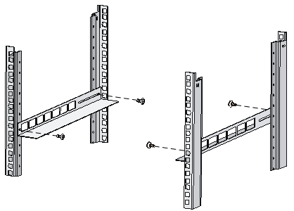
3. Attach the slide rails to the rack. See Figure 12 for reference.
Figure 12 Installing slide rails
4. Holding both sides of the device, push the device in the rack along the slide rails, as shown in Figure 13. Make sure the chassis bottom makes close contact with the bottom flanges of the slide rails.
Figure 13 Installing the device to the rack
5. Attach the front mounting brackets on the device to the front rack posts with M6 screws and cage nuts.
|
|
NOTE: Keep a minimum distance of 1 U (44.45 mm, or 1.75 in) between devices for heat dissipation. |
Grounding the device
|
|
WARNING! · Correctly connecting the grounding cable is crucial to lightning protection and EMI protection. Before you install and use the device, make sure the device is reliably grounded. · Connect the grounding cable to the grounding system in the equipment room. Do not connect it to a fire main or lightning rod. |
To ground the device:
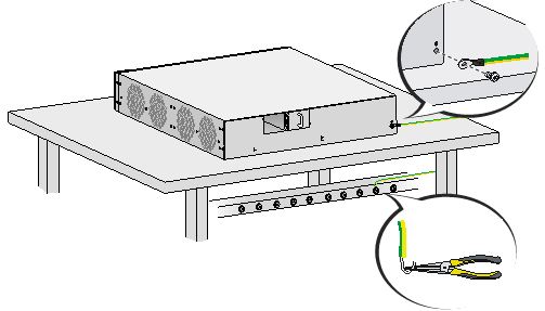
1. Use a Phillips screwdriver to remove the grounding screw from the chassis.
2. Use the grounding screw to attach one end (with ring terminal) of the grounding cable to the chassis.
3. Connect the other end of the grounding cable according to the grounding method you use:
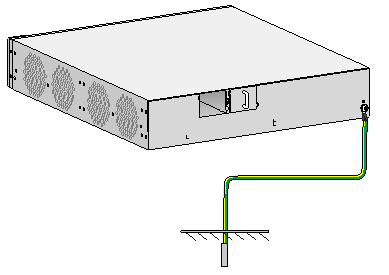
¡ Ground the device with a grounding strip—If a grounding strip is available at the installation site, connect the other end of the grounding cable to the grounding strip and make sure the grounding strip has been reliably grounded.
Figure 14 Grounding the device with a grounding strip
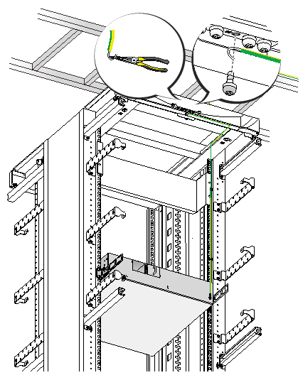
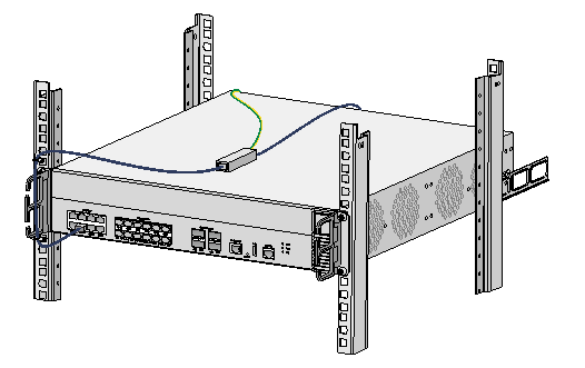
¡ Ground the device with the rack—Connect the other end of the grounding cable to the grounding point on the rack and make sure the rack has been reliably grounded.
Figure 15 Grounding the device with the rack (1)
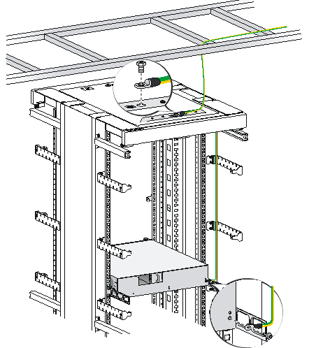
Figure 16 Grounding the device with the rack (2)
¡ Grounding the device with a grounding conductor buried in the earth—If earth is available at the installation site, hammer a 0.5 m (1.64 ft) or longer angle iron or steel tube into the earth to serve as a grounding conductor. Weld the yellow-green grounding cable to the angel iron or steel tube and treat the joint for corrosion protection.
Figure 17 Grounding the device by burying the grounding conductor into the earth
Installing optional components
Installing a lightning arrester for a network port
|
|
IMPORTANT: Before installing a lightning arrester for a network port, read the instructions that come with the lightning arrester. |
No lightning arrester is provided with the device. Purchase a lighting arrester yourself as required.
If part of the network cable of a 10/100/1000 Mbps RJ-45 copper Ethernet port must be routed outdoors, install a lightning arrester for the network port.
Installation procedure
To install a lightning arrester for a network port:
1. Use a double-faced adhesive tape to stick the lightning arrester onto the device chassis, and make sure it is as close to the grounding screw of the device as possible.
2. Measure the distance between the arrester and the grounding screw of the device, cut the ground wire of the arrester as needed, and securely tighten the ground wire to the grounding screw of the device.
3. Use the multimeter to measure whether the ground wire of the arrester makes contact with the grounding screw of the chassis.
4. Insert the outdoor network cable into the arrester's Surge end, and insert the cable connected to the device into the Protect end. Examine the indicators on the lightning arrester to verify that the connection is correct.
Figure 18 Installing a lightning arrester for a network port
Precautions
If the performance of the lightning arrester is adversely affected in the following situations, follow the recommended solution:
· Problem 1—The lightning arrester is installed in reverse direction.
Solution—Connect the Surge end to the outdoor network cable and the Protect end to the network port on the device.
· Problem 2—The lightning arrester is not correctly grounded.
Solution—Use the multimeter to confirm that the ground wire for the arrester is as short as possible to make sure it makes good contact with the grounding screw of the device.
· Problem 3—The installed lightning arresters are not sufficient.
Solution—If the device has more than one network port to connect to other devices through outdoor cables, install a lightning arrester for each network port.
Installing a lightning arrester for an AC power module
|
|
IMPORTANT: Before installing a lightning arrester for an AC power module, read the instructions in the document that comes with the arrester. |
No lightning arrester is provided with the device. Purchase one as needed.
If part of the AC power cord is routed outdoors, install a lightning arrester to protect the device from being damaged by lightning strikes. First connect the AC power cord routed from outdoors to the lightning arrester and then connect the power cord from the device to the arrester.
You can attach the lightning arrester to the rack, workbench, or a wall of the equipment room.
Connecting the console cable and setting terminal parameters
To configure and manage the device through the console port, you must run a terminal emulator program, TeraTermPro or PuTTY, on your configuration terminal. You can use the emulator program to connect a network device, a Telnet site, or an SSH site. For more information about the terminal emulator programs, see the user guides for these programs
The following are the required terminal settings:
· Bits per second—9600.
· Data bits—8.
· Stop bits—1.
· Parity—None.
· Flow control—None.
Connecting the Ethernet cables
Connecting a copper Ethernet port
1. Connect one end of the Ethernet cable to the copper Ethernet port of the device, and the other end to the Ethernet port of the peer device.
2. After powering on the device, examine the LEDs of the fixed copper Ethernet port.
For more information about the LED description, see "Appendix B LEDs."
Connecting a fiber port
No transceiver module is provided with the device. The device supports only LC-type fiber connectors. For transceiver module specifications, see "Appendix A Chassis views and technical specifications."
Follow these guidelines when you connect an optical fiber:
· Never stare into an open fiber port, because invisible rays might be emitted from the fiber port.
· Cover the dust plug if no optical fiber connector is connected to the fiber port.
· Never bend or curve a fiber when connecting it. After a fiber is installed correctly, the bend radius must be not less than 10 cm (3.94 in).
· Keep the fiber end clean.
· Make sure the Tx and Rx ports on a transceiver module are correctly connected.
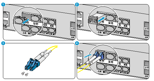
To connect the device to the network through an optical fiber:
1. Remove the dust plug on the fiber port.
2. Remove the dust cover from the transceiver module, and insert the transceiver module into the fiber port.
3. Remove the dust cover of the optical fiber connector.
4. Identify the Rx and Tx ports on the transceiver module. Use optical fibers with LC connectors to connect the Rx port and Tx port on the transceiver module to the Tx port and Rx port on the peer end, respectively.
Figure 19 Connecting an optical fiber
5. Power on the device, and examine the SFP port LEDs:
¡ If the LED is on, a fiber link has been set up.
¡ If the LED is off, no link has been set up. The reason might be wrong connection of the Tx and Rx ends. Connect the Tx and Rx ends at one end of the fiber again.
Installing power modules
|
|
CAUTION: Do not install AC and DC power modules on the same device. |
To install a power module:
1. Remove the filler panel (if any) from the target slot.
Keep the remove filler panel for future use.
2. Holding the handle of the power module with one hand and supporting the bottom of the power module with the other, push the power module into the slot along the guide rails until it clicks into the place.
Figure 20 Installing an AC power module
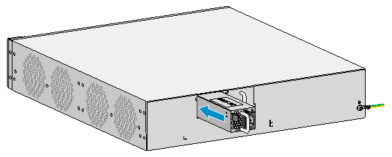
Figure 21 Installing a DC power module

Connecting the AC power cord
|
|
CAUTION: Before connecting the AC power cord, make sure the device is reliably grounded. |
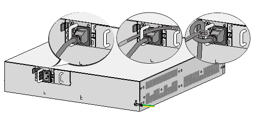
To connect the AC power cord:
1. Connect one end of the AC power cord to the AC-input power receptacle on the device.
2. Use a cable tie to secure the power cord to the power module handle.
3. Connect the other end of the AC power cord to the AC power source.
Figure 22 Connecting an AC power cord
Connecting the DC power cord
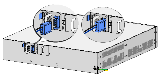
1. Correctly orient the DC power cord plug and insert the power cord into the DC-input receptacle.
The plug and receptacle are fool proof. If you orient the plug with the upside down, you cannot insert the plug into the receptacle.
2. Connect the other end of the DC power cord to the DC power source.
Figure 23 Connecting a DC power cord
Verifying the installation
Before powering on the device, verify the following information:
· The correct power source is used.
· The grounding cable is securely connected.
· The console cable and power cord are correctly connected.
· All the interface cables are cabled indoors. If any cable is routed outdoors, verify that the socket strip with a lightning arrester for network ports has been properly connected.
Powering on the device
1. Power on the device. The device initializes its memory and runs the BootWare. The following information appears on the terminal screen:
System is starting...
Press Ctrl+D to access BASIC-BOOTWARE MENU
Press Ctrl+T to start heavy memory test
Booting Normal Extended BootWare
The Extended BootWare is self-decompressing.....Done.
****************************************************************************
* *
* H3C WX5860H BootWare, Version 7.1.064 *
* *
****************************************************************************
Compiled Date : Jan 1 2018
CPU Type : XLP432
CPU Clock Speed : 1400MHz
Memory Type : DDR3 SDRAM
Memory Size : 32768MB
Memory Speed : 1333MHz
BootWare Size : 768KB
Flash Size : 16MB
cfa0 Size : 4002MB
CPLD1 Version : 001
CPLD2 Version : 001
PCB Version : Ver.A
BootWare Validating...
Press Ctrl+B to access EXTENDED-BOOTWARE MENU...
2. Press Ctrl + B at the prompt within 4 seconds to access the Boot menu. Otherwise, the system enters the system image file reading and self-compressing process.
To access the Boot menu after the system enters the system image file reading and self-compressing process, restart the device.
Loading the main image files...
Loading file cfa0:/wx5860h-system.bin.......................................
.......................Done.
Loading file cfa0:/wx5860h-boot.bin.........................................
............................................................................
......Done.
Image file cfa0:/wx5860h-boot.bin is self-decompressing.....................
....................................Done.
System image is starting...
…
Press Ctrl+I to enter inter-initiate mode... 0 s
…
Line con0 is available.
Press ENTER to get started.
3. Press Enter at the prompt, and you can configure the device when the prompt <H3C> appears.
During the startup process, the CPLD is automatically upgraded to the most recent version.
