- Table of Contents
-
- 02-Layer 2 Configuration Guide
- 00-Preface
- 01-Ethernet Interface Configuration
- 02-Loopback and Null Interface Configuration
- 03-MAC Address Table Configuration
- 04-Ethernet Link Aggregation Configuration
- 05-Port Isolation Configuration
- 06-Spanning Tree Configuration
- 07-VLAN Configuration
- 08-GVRP Configuration
- 09-LLDP Configuration
- Related Documents
-
| Title | Size | Download |
|---|---|---|
| 01-Ethernet Interface Configuration | 166.64 KB |
Contents
Ethernet interface configuration
Ethernet interface naming conventions
Configuring basic settings of an Ethernet interface
Configuring Duplex Mode and Speed on an Ethernet Interface
Setting speed options for auto negotiation on an Ethernet interface
Configuring flow control on an Ethernet interface
Configuring physical state change suppression on an Ethernet interface
Configuring loopback testing on an Ethernet interface
Enabling the auto power-down function on an Ethernet interface
Configuring storm control on an Ethernet interface
Setting the statistics polling interval
Configuring jumbo frame support
Enabling loopback detection on an Ethernet interface
Setting the MDI mode of an Ethernet interface
Enabling bridging on an Ethernet interface
Testing the cable connection of an Ethernet interface
Displaying and maintaining an Ethernet interface
This chapter includes these sections:
· Ethernet interface naming conventions
· Configuring basic settings of an Ethernet interface
· Displaying and maintaining an Ethernet interface
|
|
NOTE: · The term "switch" or "device" in this chapter refers to the switching engine on a WX3000E wireless switch. · The WX3000E series comprises WX3024E and WX3010E wireless switches. · The port numbers in this chapter are for illustration only. |
Ethernet interface naming conventions
The Ethernet interfaces on the WX3000E switching engines are named in the format of interface-type A/B/C, where the following definitions apply:
· A—1.
· B—Represents a slot number on the switch, and its value is 0.
· C—Represents the number of an interface.
Configuring basic settings of an Ethernet interface
Configuring Duplex Mode and Speed on an Ethernet Interface
You can set an Ethernet interface to operate in one of the following duplex modes:
· Full-duplex mode (full): Interfaces operating in this mode can send and receive packets simultaneously.
· Half-duplex mode (half): Interfaces operating in this mode cannot send and receive simultaneously.
· Auto-negotiation mode (auto): Interfaces operating in this mode negotiate a duplex mode with their peers.
Similarly, you can set the speed of an Ethernet interface or enable it to automatically negotiate a speed with its peer. For a 1000-Mbps Ethernet interface, you can also set speed options for auto negotiation. The two ends can pick a speed only from the available options. For more information, see “
Setting speed options for auto negotiation on an Ethernet interface.”
Follow these steps to configure an Ethernet interface:
|
To do… |
Use the command… |
Remarks |
|
Enter system view |
system-view |
— |
|
Enter Ethernet interface view |
interface interface-type interface-number |
— |
|
Set the interface description |
description text |
Optional By default, the description of an interface is in the format of interface-name Interface. For example, GigabitEthernet1/0/1 Interface. |
|
Set the duplex mode of the interface |
duplex { auto | full | half } |
Optional By default, the duplex mode is auto. Fiber interfaces do not support the half keyword. |
|
Set the port speed |
speed { 10 | 100 | 1000 | auto } |
Optional auto by default. The SFP fiber ports do not support the 10 or 100 keyword. |
|
Shut down the Ethernet interface |
shutdown |
Required By default, Ethernet interfaces are up. |
Setting speed options for auto negotiation on an Ethernet interface
Speed auto negotiation enables an Ethernet interface to negotiate with its peer for the highest speed supported by both ends by default. You can narrow down the speed option list for negotiation.
Figure 1 Speed auto negotiation application scenario
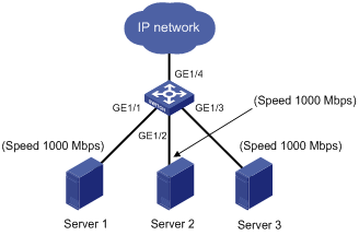
As shown in Figure 1, all ports on Switch A are operating in speed auto negotiation mode, with the highest speed of 1000 Mbps. If the transmission rate of each server in the server cluster is 1000 Mbps, their total transmission rate will exceed the capability of port GigabitEthernet 1/4, the port providing access to the Internet for the servers.
To avoid congestion on GigabitEthernet 1/4, set 100 Mbps as the only option available for speed negotiation on port GigabitEthernet 1/1, GigabitEthernet 1/2, and GigabitEthernet 1/3. As a result, the transmission rate on each port connected to a server is limited to 100 Mbps.
Follow these steps to set speed options for auto negotiation on an Ethernet interface:
|
To do… |
Use the command… |
Remarks |
|
Enter system view |
system-view |
— |
|
Enter Ethernet interface view |
interface interface-type interface-number |
— |
|
Set speed options for auto negotiation |
speed auto { 10 | 100 | 1000 } * |
Optional |
|
|
NOTE: · This function is available only for 1000-Mbps Ethernet interfaces that support speed auto negotiation. · The speed and speed auto commands supersede each other, and whichever is configured last takes effect. |
Configuring flow control on an Ethernet interface
To avoid packet drops on a link, you can enable flow control at both ends of the link. When traffic congestion occurs at the receiving end, the receiving end sends a flow control (Pause) frame to ask the sending end to suspend sending packets
Follow these steps to enable flow control on an Ethernet interface:
|
To do… |
Use the command… |
Remarks |
|
Enter system view |
system-view |
— |
|
Enter Ethernet interface view |
interface interface-type interface-number |
— |
|
Enable TxRx flow control |
flow-control |
Required By default, Rx flow control is disabled on an Ethernet interface. |
Configuring physical state change suppression on an Ethernet interface
The physical link state of an Ethernet interface is either up or down. Each time the physical link of a port goes up or comes down, the physical layer reports the change to the upper layers, and the upper layers handle the change, resulting in increased overhead.
To prevent physical link flapping from affecting system performance, configure physical state change suppression to delay the reporting of physical link state changes. The physical layer reports the changes only when the delay expires.
Follow these steps to configure physical state change suppression on an Ethernet interface:
|
To do… |
Use the command… |
Remarks |
|
Enter system view |
system-view |
— |
|
Enter Ethernet interface view |
interface interface-type interface-number |
— |
|
Set a physical state change suppression interval |
link-delay delay-time |
Required By default, physical state change suppression is disabled. |
Configuring loopback testing on an Ethernet interface
If an Ethernet interface does not work normally, you can enable loopback testing on it to identify the problem. Loopback testing has the following types:
· Internal loopback testing—Tests all on-chip functions related to Ethernet interfaces.
· External loopback testing—Tests hardware of Ethernet interfaces. To perform external loopback testing on an Ethernet interface, connect a loopback plug to the Ethernet interface. The device sends test packets out the interface, which are expected to loop over the plug and back to the interface. If the interface fails to receive any test packet, the hardware of the interface is faulty.
An Ethernet interface in a loopback test does not forward data traffic.
Follow these steps to enable loopback testing on an Ethernet interface:
|
To do… |
Use the command… |
Remarks |
|
Enter system view |
system-view |
— |
|
Enter Ethernet interface view |
interface interface-type interface-number |
— |
|
Enable loopback testing |
loopback { external | internal } |
Optional Disabled by default. |
|
|
NOTE: · On an interface that is physically down, you can only perform internal loopback testing. On an interface administratively shut down, you can perform neither internal nor external loopback testing. · The speed, duplex, mdi, and shutdown commands are unavailable during loopback testing. · During loopback testing, an Ethernet interface works in full duplex mode. When you disable loopback testing, the duplex configuration of the interface restores. · The loopback configuration is executed for only once, and is not saved in the configuration file. |
Configuring a port group
Some interfaces on your device may use the same set of settings. To configure these interfaces in bulk rather than one by one, you can assign them to a port group.
You create port groups manually. All settings made for a port group apply to all the member ports of the group. For example, you can configure a traffic suppression threshold (see “Configuring storm suppression”) for multiple interfaces in bulk by assigning these interfaces to a port group.
Even though the settings are made on the port group, they are saved on an interface basis rather than on a port group basis. You can only view the settings in the view of each interface by use the display current-configuration or display this command.
Follow these steps to configure a manual port group:
|
To do… |
Use the command… |
Remarks |
|
Enter system view |
system-view |
— |
|
Create a manual port group and enter manual port group view |
port-group manual port-group-name |
Required |
|
Assign Ethernet interfaces to the manual port group |
group-member interface-list |
Required |
Enabling the auto power-down function on an Ethernet interface
To save power, enable the auto power-down function on Ethernet interfaces. With this function, the system automatically stops supplying power to an interface if the interface is in the down state for a certain period of time (which depends on the chip specifications and is not configurable). The interface enters the power save mode. When the interface goes up, the system supplies power to the interface and the interface enters its normal state.
Follow these steps to enable auto power-down on an Ethernet interface:
|
To do… |
Use the command… |
Remarks |
|
|
Enter system view |
system-view |
— |
|
|
Enter Ethernet interface view or port group view |
Enter Ethernet interface view |
interface interface-type interface-number |
Use either command. To enable auto power-down on an Ethernet interface, enter Ethernet interface view. To enable auto power-down on a group of Ethernet interfaces, enter port group view. |
|
Enter port group view |
port-group manual port-group-name |
||
|
Enable auto power-down on an Ethernet interface |
port auto-power-down |
Required Disabled by default. |
|
Configuring storm suppression
You can use the storm suppression function to limit the size of a particular type of traffic (broadcast, multicast, or unknown unicast traffic) as a whole globally in system view or on a per-interface basis in Ethernet interface view or port group view.
· In system view, you set the maximum size of broadcast, multicast, or unknown unicast traffic allowed to pass through the system as a whole. When the sum of broadcast, multicast, or unknown unicast traffic arriving on all interfaces of the system exceeds this threshold, the system discards packets until the traffic drops below this threshold.
· In interface or port group view, you set the maximum size of broadcast, multicast or unknown unicast traffic allowed to pass through an interface or each interface in a port group. When the broadcast, multicast, or unknown unicast traffic on the interface exceeds this threshold, the system discards packets until the traffic drops below this threshold.
|
|
NOTE: When you want to perform storm control for different type of packets, you can configure a suppression threshold ratio or use the storm-constrain command to configure storm control for each type of packets. However, when you want to perform storm control for the same type of packets, you cannot use the two methods at the same time; otherwise, the storm control result may be not as expected. |
Follow these steps to set storm suppression thresholds on one or multiple Ethernet interfaces:
|
To do… |
Use the command… |
Remarks |
|
|
Enter system view |
system-view |
— |
|
|
Enter Ethernet interface view or port group view |
Enter Ethernet interface view |
interface interface-type interface-number |
Use either command. To configure storm suppression on an Ethernet interface, enter Ethernet interface view. To configure storm suppression on a group of Ethernet interfaces, enter port group view. |
|
Enter port group view |
port-group manual port-group-name |
||
|
Set the broadcast suppression threshold ratio |
broadcast-suppression { ratio | pps max-pps | kbps max-kbps } |
Optional By default, broadcast traffic is not suppressed. |
|
|
Set the multicast suppression threshold ratio |
multicast-suppression { ratio | pps max-pps | kbps max-kbps } |
Optional By default, multicast traffic is not suppressed. |
|
|
Set the unknown unicast suppression threshold ratio |
unicast-suppression { ratio | pps max-pps | kbps max-kbps } |
Optional By default, unknown unicast traffic is not suppressed. |
|
|
|
NOTE: For an Ethernet interface that belongs to a port group, if you set a traffic suppression threshold for the interface in both Ethernet interface view and port group view, the threshold configured last takes effect. |
Configuring storm control on an Ethernet interface
Storm control compares broadcast, multicast, and unknown unicast traffic regularly with their respective traffic thresholds on an Ethernet interface. For each type of traffic, storm control provides a lower threshold and a higher threshold.
For management purposes, you can configure the interface to send threshold event traps and log messages when monitored traffic exceeds the upper threshold or falls below the lower threshold from the upper threshold.
When a particular type of traffic exceeds its upper threshold, the interface does either of the following, depending on your configuration:
· Blocks this type of traffic, while forwarding other types of traffic. Even though the interface does not forward the blocked traffic, it still counts the traffic. When the blocked traffic is detected dropping below the lower threshold, the port begins to forward the traffic.
· Shuts down automatically. The interface shuts down automatically and stops forwarding any traffic. When the blocked traffic is detected dropping below the lower threshold, the port does not forward the traffic. To bring up the interface, use the undo shutdown command or disable the storm control function.
|
|
CAUTION: Alternatively, you can configure the storm suppression function to control a specific type of traffic. Do not enable them both on an Ethernet interface at the same time because the storm suppression and storm control functions are mutually exclusive. For example, with an unknown unicast suppression threshold set on an Ethernet interface, do not enable storm control for unknown unicast traffic on the interface. For more information about storm suppression, see “Configuring storm suppression.” |
Follow these steps to configure storm control on an Ethernet interface:
|
To do… |
Use the command… |
Remarks |
|
Enter system view |
system-view |
— |
|
Set the traffic polling interval of the storm control module |
storm-constrain interval seconds |
Optional 10 seconds by default. |
|
Enter Ethernet interface view |
interface interface-type interface-number |
— |
|
Enable storm control, and set the lower and upper thresholds for broadcast, multicast, or unknown unicast traffic |
storm-constrain { broadcast | multicast | unicast } pps max-pps-values min-pps-values |
Required Disabled by default. |
|
Set the control action to take when monitored traffic exceeds the upper threshold |
storm-constrain control { block | shutdown } |
Optional Disabled by default. |
|
Enable the interface to send storm control threshold event traps. |
storm-constrain enable trap |
Optional By default, the interface sends traps when monitored traffic exceeds the upper threshold or drops below the lower threshold from the upper threshold. |
|
Enable the interface to log storm control threshold events. |
storm-constrain enable log |
Optional By default, the interface outputs log messages when monitored traffic exceeds the upper threshold or falls below the lower threshold from the upper threshold. |
|
|
NOTE: · For network stability, use the default or set a higher traffic polling interval. · Storm control uses a complete polling cycle to collect traffic data, and analyzes the data in the next cycle. It takes a port at least one polling interval and at most two polling intervals to take a storm control action. · The storm control function allows you to set the upper and lower thresholds for all three types of packets respectively on the same interface. |
Setting the statistics polling interval
Follow these steps to set the statistics polling interval globally or on an Ethernet interface:
|
To do… |
Use the command… |
Remarks |
|
Enter system view |
system-view |
— |
|
Enter Ethernet interface view |
interface interface-type interface-number |
— |
|
Set the statistics polling interval |
flow-interval interval |
Optional 300 seconds by default. |
Configuring jumbo frame support
An Ethernet interface may receive some frames larger than the standard Ethernet frame size (1518 bytes), called "jumbo frames", during high-throughput data exchanges such as file transfers.
With jumbo frame support enabled, the interface can process frames larger than the standard Ethernet frame size (1518 bytes) yet within 10240 bytes. With jumbo frame support disabled, the interface drops the incoming frames larger than 1518 bytes.
Follow these steps to configure jumbo frame support in system view:
|
To do… |
Use the command… |
Remarks |
|
Enter system view |
system-view |
— |
|
Enable jumbo frame support |
jumboframe enable |
Optional Enabled by default. |
Enabling loopback detection on an Ethernet interface
If a device receives a packet that it sent out, a loop has occurred to the device. Loops may cause broadcast storms, which degrade network performance. You can use this feature to detect whether a loop has occurred.
Depending on whether the receiving interface is the same as the sending interface, loops fall into the following type: single-port loopback and multi-port loopback.
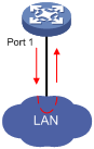
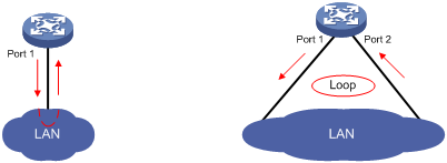
· Single-port loopback occurs when an interface receives a packet that it sent out and the receiving interface is the same as the sending interface, as shown in Figure 2.
· Multi-port loopback occurs when a device receives a packet that it sent out but the receiving interface may not be the sending interface, as shown in Figure 3.
You can enable loopback detection to detect loops on an interface and, if the interface supports the loopback-detection action command, configure the protective action to take on the receiving interface when a loop is detected, for example, to shut down the interface. Depending on whether a protective action is configured, the device takes the actions in Table 1 to alleviate the impact of the loop condition.
Table 1 Actions to take upon detection of a loop condition
|
Port type |
Actions |
|
|
No protective action is configured |
A protective action is configured |
|
|
Access port |
· Place the receiving interface in controlled mode. The interface discards all incoming packets, but still forwards outgoing packets. · Generate traps. · Delete all MAC address entries of the interface. |
· Perform the configured protective action. · Generate traps and log messages. · Delete all MAC address entries of the interface. |
|
Hybrid or trunk port |
· Generate traps. · If loopback detection control is enabled, place the receiving interface in controlled mode. The interface discards all incoming packets, but still forwards outgoing packets. · Delete all MAC address entries of the interface. |
· Create traps and log messages. · If loopback detection control is enabled, take the configured protective action on the interface. · Delete all MAC address entries of the interface. |
Follow these steps to configure loopback detection:
|
To do… |
Use the command… |
Remarks |
|
|
Enter system view |
system-view |
— |
|
|
Enable global loopback detection |
loopback-detection enable |
Required Disabled by default. |
|
|
Enable multi-port loopback detection |
loopback-detection multi-port-mode enable |
Optional By default, multi-port loopback detection is disabled, and the device can only detect single-port loopback. |
|
|
Set the loopback detection interval |
loopback-detection interval-time time |
Optional 30 seconds by default. |
|
|
Enter Ethernet interface view or port group view |
Enter Ethernet interface view |
interface interface-type interface-number |
Use either command To configure loopback detection on one interface, enter Ethernet interface view. To configure loopback detection on a group of Ethernet interfaces, enter port group view. |
|
Enter port group view |
port-group manual port-group-name |
||
|
Enable loopback detection on the interface |
loopback-detection enable |
Required Disabled by default. |
|
|
Enable loopback detection control on a trunk port or a hybrid port |
loopback-detection control enable |
Optional Disabled by default. |
|
|
Enable loopback detection in all the VLANs on the trunk or hybrid port |
loopback-detection per-vlan enable |
Optional By default, a trunk or hybrid port performs loopback detection only in its default VLAN. |
|
|
Set the protective action to take on the interface when a loop is detected |
loopback-detection action { block | no-learning | semi-block | shutdown } |
Optional With the shutdown keyword specified, the looped port will be automatically shut down and its physical state changes to Loop down. After the loop is removed, use the undo shutdown command on the port to recover its forwarding capability. |
|
|
|
NOTE: · To use loopback detection on an Ethernet interface, you must enable the function both globally and on the interface. · To disable loopback detection on all interfaces, run the undo loopback-detection enable command in system view. · To enable a hybrid or trunk port to take the administratively specified protective action, you must perform the loopback-detection control enable command on the port. · When you change the link type of an Ethernet interface with the port link-type command, the switch removes the protective action configured on the interface. For more information about the port link-type command, see the Layer 2 Command Reference. |
Setting the MDI mode of an Ethernet interface
|
|
NOTE: Fiber interfaces do not support the MDI mode setting. |
You can use both crossover and straight-through Ethernet cables to connect copper Ethernet interfaces. To accommodate these two types of cables, a copper Ethernet interface can operate in one of the following Medium Dependent Interface (MDI) modes:
· Across mode
· Normal mode
· Auto mode
A copper Ethernet interface uses an RJ-45 connector, which comprises eight pins, each playing a dedicated role. For example, pins 1 and 2 transmit signals, and pins 3 and 6 receive signals. The pin role varies by the following MDI modes:
· In normal mode, pins 1 and 2 are transmit pins, and pins 3 and 6 are receive pins.
· In across mode, pins 1 and 2 are receive pins, and pins 3 and 6 are transmit pins.
· In auto mode, the interface negotiates pin roles with its peer.
To enable the interface to communicate with its peer, ensure that its transmit pins are connected to the remote receive pins. If the interface can detect the connection cable type, set the interface in auto MDI mode. If not, set its MDI mode using the following guidelines:
· When a straight-through cable is used, set the interface to work in the MDI mode different than its peer.
· When a crossover cable is used, set the interface to work in the same MDI mode as its peer, or set either end to work in auto mode.
Follow these steps to set the MDI mode of an Ethernet interface:
|
To do… |
Use the command… |
Remarks |
|
Enter system view |
system-view |
— |
|
Enter Ethernet interface view |
interface interface-type interface-number |
— |
|
Set the MDI mode of the Ethernet interface |
mdi { across | auto | normal } |
Optional By default, a copper Ethernet interface operates in auto mode to negotiate pin roles with its peer. |
Enabling bridging on an Ethernet interface
When an incoming packet arrives, the device looks up the destination MAC address of the packet in the MAC address table. If an entry is found, but the outgoing interface is the same as the receiving interface, the device discards the packet.
To enable the device to forward such packets rather than drop them, enable the bridging function on the Ethernet interface.
Follow these steps to enable bridging on an Ethernet interface:
|
To do… |
Use the command… |
Remarks |
|
Enter system view |
system-view |
— |
|
Enter Ethernet interface view |
interface interface-type interface-number |
— |
|
Enable bridging on the Ethernet interface |
port bridge enable |
Required Disabled by default. |
Testing the cable connection of an Ethernet interface
|
|
NOTE: · Fiber interfaces do not support this feature. · If the link of an Ethernet port is up, testing its cable connection will cause the link to come down and then go up. |
You can test the cable connection of an Ethernet interface for a short or open circuit. The device displays cable test results within five seconds. If any fault is detected, the test results include the length of the faulty cable segment.
Follow these steps to test the cable connection of an Ethernet interface:
|
To do… |
Use the command… |
Remarks |
|
Enter system view |
system-view |
— |
|
Enter Ethernet interface view |
interface interface-type interface-number |
— |
|
Test the cable connected to the Ethernet interface |
virtual-cable-test |
Required |
Displaying and maintaining an Ethernet interface
|
To do… |
Use the command… |
Remarks |
|
Display Ethernet interface or subinterface information |
display interface [ interface-type ] brief [ down ] [ | { begin | exclude | include } regular-expression ] display interface interface-type interface-number [ brief ] [ | { begin | exclude | include } regular-expression ] |
Available in any view |
|
Display information about a manual port group or all manual port groups |
display port-group manual [ all | name port-group-name ] [ | { begin | exclude | include } regular-expression ] |
Available in any view |
|
Display information about the loopback function |
display loopback-detection [ | { begin | exclude | include } regular-expression ] |
Available in any view |
|
Display information about storm control |
display storm-constrain [ broadcast | multicast | unicast ] [ interface interface-type interface-number ] [ | { begin | exclude | include } regular-expression ] |
Available in any view |
|
Clear the interface or subinterface statistics |
reset counters interface [ interface-type [ interface-number ] ] |
Available in user view |