- Table of Contents
-
- 02-Layer 2 Configuration Guide
- 00-Preface
- 01-Ethernet Interface Configuration
- 02-Loopback and Null Interface Configuration
- 03-MAC Address Table Configuration
- 04-Ethernet Link Aggregation Configuration
- 05-Port Isolation Configuration
- 06-Spanning Tree Configuration
- 07-VLAN Configuration
- 08-GVRP Configuration
- 09-LLDP Configuration
- Related Documents
-
| Title | Size | Download |
|---|---|---|
| 08-GVRP Configuration | 162.07 KB |
Displaying and maintaining GVRP
GVRP normal registration mode configuration example
GVRP fixed registration mode configuration example
GVRP forbidden registration mode configuration example
The Generic Attribute Registration Protocol (GARP) provides a generic framework for devices in a switched LAN, such as end stations and switches, to register and deregister attribute values. The GARP VLAN Registration Protocol (GVRP) is a GARP application that registers and deregisters VLAN attributes. GVRP uses the operating mechanism of GARP to maintain and propagate dynamic VLAN registration information for the GVRP devices on the network.
This chapter includes these sections:
· GVRP configuration task list
· Displaying and maintaining GVRP
|
|
NOTE: · The term "switch" or "device" in this chapter refers to the switching engine on a WX3000E wireless switch. · The WX3000E series comprises WX3024E and WX3010E wireless switches. · The port numbers in this chapter are for illustration only. |
Introduction to GVRP
GARP
GARP provides a mechanism that allows participants in a GARP application to distribute, propagate, and register with other participants in a LAN the attributes specific to the GARP application, such as VLAN or multicast address attributes.
How GARP works
Each port that participates in a GARP application (GVRP for example) is a GARP participant.
GARP enables GARP participants to propagate attribute values throughout the switched LAN. As shown in Figure 1, a GARP participant registers and deregisters its attribute values with other GARP participants by sending and withdrawing declarations, and registers and deregisters the attribute values of other participants according to the declarations and withdrawals it has received.
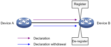
For example, a GVRP-enabled port registers and deregisters VLAN in the following cases.
· When the port receives a VLAN attribute declaration, it registers the VLAN attribute and joins the VLAN.
· When the port receives a VLAN withdrawal, it deregisters the VLAN and leaves the VLAN.
GARP messages
A GARP participant exchanges information with other GARP participants by sending GARP messages: Join, Leave, and LeaveAll. As a GARP application, GVRP also uses GARP messages for information exchange.
1. Join messages
A GARP participant sends Join messages when it wishes to declare its attribute values or receives Join messages from other GARP participants.
Join messages fall into JoinEmpty and JoinIn. A GARP participant sends JoinEmpty messages to declare attribute values that it has not registered. It sends JoinIn messages to declare attribute values that it has registered.
2. Leave messages
A GARP participant sends Leave messages when it wishes to withdraw declarations of its attribute values (because, for example, it has deregistered its attribute values), or receives Leave messages from other participants.
Leave messages fall into LeaveEmpty and LeaveIn. A GARP participant sends LeaveEmpty messages to withdraw declarations of the attribute values that it has not registered. It sends LeaveIn messages to withdraw declarations of the attribute values that it has registered.
3. LeaveAll messages
A GARP participant sends a LeaveAll message when it declares that it is deregistering all attribute values or receives LeaveAll messages from other participants. If any participants want to maintain the registration for a particular attribute value, they must send a Join message.
GARP timers
|
|
NOTE: · The settings of GARP timers apply to all GARP applications, such as GVRP, on a LAN. · On a GARP-enabled network, each port maintains its own Hold, Join, and Leave timers, but only one LeaveAll timer is maintained on each device. This LeaveAll timer applies to all ports on the device. · The value ranges for the Hold, Join, Leave, and LeaveAll timers are dependent on one another. See Table 2 for their dependencies. |
H3C's implementation of GARP uses the following timers to control GARP message transmission:
1. Hold timer
The Hold timer sets the delay that a GARP participant waits before sending a Join or Leave message.
When an attribute value changes or a Join or Leave message arrives, the GARP participant does not send the message immediately. Rather, it assembles Join and Leave messages in the least number of GARP PDUs, and sends them out when the Hold timer expires. This timer reduces the number of GARP PDUs and saves bandwidth.
2. Join timer
A GARP participant may declare an attribute twice to ensure reliable transmission. The Join timer sets the interval between the two declarations.
A GARP participant starts a Join timer when it declares an attribute value or receives a JoinIn message for the attribute value. If the GARP participant does not receive any declaration for the attribute value when the Join timer expires, it re-declares the attribute value.
|
|
NOTE: Because all attributes of a GARP participant share the same Join timer, you must set the Join timer long enough so that all attributes can be sent out in one declaration. |
3. Leave timer
A GARP participant starts a Leave timer when it receives a Leave message for an attribute value. If the GARP participant has not received a Join message for the attribute value before the timer expires, it deregisters the attribute value.
4. LeaveAll timer
When a GARP application is enabled, a LeaveAll timer starts. The GARP participant sends a LeaveAll message when the timer expires. Then, the LeaveAll timer restarts to begin a new cycle. The LeaveAll timer and all other GARP timers also restart when the GARP participant receives a LeaveAll message.
|
|
NOTE: · Set the LeaveAll timer greater than any Leave timer because each time a LeaveAll timer expires, a network-wide re-join occurs. · A device may send LeaveAll messages at the interval set by its LeaveAll timer or the LeaveAll timer on another device on the network, whichever is smaller. This is because each time a device on the network receives a LeaveAll message it resets its LeaveAll timer. |
GARP PDU format
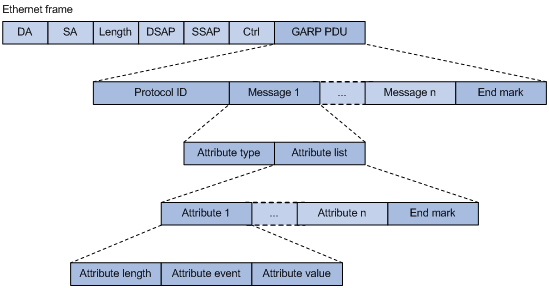
As shown in Figure 2, GARP PDUs are encapsulated in IEEE 802.3 Ethernet frames.
|
Field |
Description |
Value |
|
Protocol ID |
Protocol identifier for GARP |
0x0001 |
|
Message |
One or multiple messages, each containing an attribute type and an attribute list |
–– |
|
End mark |
Indicates the end of a GARP PDU |
0x00 |
|
Attribute type |
Defined by the GARP application |
0x01 for GVRP, indicating the VLAN ID attribute |
|
Attribute list |
Contains one or multiple attributes |
–– |
|
Attribute |
Consists of an Attribute Length, an Attribute Event, and an Attribute Value |
–– |
|
Attribute length |
Length of an attribute, inclusive of the attribute length field |
2 to 255 (in bytes) |
|
Attribute event |
Event described by the attribute |
· 0x00: LeaveAll event · 0x01: JoinEmpty event · 0x02: JoinIn event · 0x03: LeaveEmpty event · 0x04: LeaveIn event · 0x05: Empty event |
|
Attribute value |
Attribute value |
VLAN ID for GVRP If the value of the Attribute event field is 0x00 (LeaveAll event), the Attribute value field is invalid. |
The destination MAC addresses of GARP messages are multicast MAC addresses, and vary with GARP applications. For example, the destination MAC address of GVRP is 01-80-C2-00-00-21.
GVRP
GVRP overview
As a GARP application, GVRP uses the operating mechanism of GARP to maintain and propagate dynamic VLAN registrations throughout a switched LAN.
In a switched LAN, each GVRP-enabled switch sends and receives VLAN declarations and withdrawals from other GVRP-enabled switches, and dynamically updates its local database, including active VLAN members and through which port each VLAN member can be reached. This ensures that all GVRP-enabled switches in a LAN maintain the same VLAN information.
The VLAN information propagated by GVRP includes not only manually configured static VLAN information but also dynamic VLAN information from other switches.
GVRP registration modes
GVRP is available on trunk ports. It provides the following registration modes:
· Normal mode – Performs dynamic VLAN registrations and deregistrations on the trunk port, and sends declarations and withdrawals for dynamic and static VLANs. VLANs manually configured are called static VLANs, and VLANs created by GVRP are called dynamic VLANs.
· Fixed mode – Disables the trunk port to register or withdraw dynamic VLAN information, but allows the port to send declarations for static VLANs. A trunk port in this mode carries only static VLANs, even if it has been assigned to all VLANs.
· Forbidden mode – Disables the trunk port to register or withdraw dynamic VLAN information, and allows the port to send declarations only for VLAN 1. A trunk port in this mode carries only VLAN 1 even if it has been assigned to any other VLANs.
Protocols and standards
· IEEE 802.1Q, Virtual Bridged Local Area Networks
GVRP configuration task list
Complete these tasks to configure GVRP:
|
Task |
Remarks |
|
Required |
|
|
Optional |
|
|
NOTE: · GVRP configuration made in Ethernet interface view or Layer 2 aggregate interface view takes effect on the current interface only; GVRP configuration made in port group view takes effect on all the member ports in the group. · GVRP configuration made on a member port in an aggregation group takes effect only after the port is removed from the aggregation group. |
Configuring GVRP functions
Before enabling GVRP on a port, you must enable GVRP globally. In addition, GVRP can be configured only on trunk ports, and you must assign the involved trunk ports to all dynamic VLANs.
Follow these steps to configure GVRP functions on a trunk port:
|
To do… |
Use the command… |
||
|
Enter system view |
system-view |
–– |
|
|
Enable GVRP globally |
gvrp |
Required Globally disabled by default. |
|
|
Enter Ethernet interface view, Layer 2 aggregate interface view, or port-group view |
Enter Ethernet interface view or Layer 2 aggregate interface view |
interface interface-type interface-number |
Required Use either command. |
|
Enter port-group view |
port-group manual port-group-name |
||
|
Configure the link type of the ports as trunk |
port link-type trunk |
Required Access by default. |
|
|
Assign the trunk ports to all VLANs |
port trunk permit vlan all |
Required By default, a trunk port is assigned to VLAN 1 only. |
|
|
Enable GVRP on the ports |
gvrp |
Required Disabled by default. |
|
|
Configure the GVRP registration mode on the port |
gvrp registration { fixed | forbidden | normal } |
Optional normal by default. |
|
|
|
NOTE: · For more information about the port link-type trunk and port trunk permit vlan all commands, see the Layer 2 Command Reference. · GVRP is mutually exclusive with service loopback. · GVRP can work with MSTP CIST. When GVRP runs on the CIST, blocked ports on the CIST cannot receive/send GVRP packets. · Do not enable both GVRP and remote port mirroring. Otherwise, GVRP may register the remote probe VLAN to unexpected ports, resulting in undesired duplicates to be received by the monitor port. For more information about port mirroring, see the Network Management and Monitoring Configuration Guide. · Enabling GVRP on a Layer 2 aggregate interface enables both the aggregate interface and all selected member ports in the corresponding link aggregation group to participate in dynamic VLAN registration and deregistration. |
Configuring the GARP timers
Follow these steps to configure the GARP timers:
|
To do… |
Use the command… |
Remarks |
|
|
Enter system view |
system-view |
–– |
|
|
Configure the GARP LeaveAll timer |
garp timer leaveall timer-value |
Optional 1000 centiseconds by default. The LeaveAll timer applies to all ports. |
|
|
Enter Ethernet interface view, Layer 2 aggregate interface view, or port-group view |
Enter Ethernet or Layer 2 aggregate interface view |
interface interface-type interface-number |
Required Use either command. |
|
Enter port-group view |
port-group manual port-group-name |
||
|
Configure the Hold timer |
garp timer hold timer-value |
Optional 10 centiseconds by default. |
|
|
Configure the Join timer |
garp timer join timer-value |
Optional 20 centiseconds by default. |
|
|
Configure the Leave timer |
garp timer leave timer-value |
Optional 60 centiseconds by default. |
|
As shown in Table 2, the value ranges for GARP timers are dependent on one another:
· If you want to set a value beyond the value range for a timer, you may change the value range by tuning the value of another related timer.
· If you want to restore the default settings of the timers, restore the Hold timer first, and then the Join, Leave, and LeaveAll timers.
Table 2 Dependencies of the GARP timers
|
Timer |
Lower limit |
Upper limit |
|
Hold |
10 centiseconds |
No greater than half of the Join timer |
|
Join |
No less than twice the Hold timer |
Less than half of the Leave timer |
|
Leave |
Greater than twice the Join timer |
Less than the LeaveAll timer |
|
LeaveAll |
Greater than the Leave timer |
32765 centiseconds |
Displaying and maintaining GVRP
|
To do… |
Use the command… |
Remarks |
|
Display statistics about GARP on ports |
display garp statistics [ interface interface-list ] [ | { begin | exclude | include } regular-expression ] |
Available in any view |
|
Display GARP timers on ports |
display garp timer [ interface interface-list ] [ | { begin | exclude | include } regular-expression ] |
Available in any view |
|
Display the local VLAN information maintained by GVRP on ports |
display gvrp local-vlan interface interface-type interface-number [ | { begin | exclude | include } regular-expression ] |
Available in any view |
|
Display the current GVRP state in the specified VLANs on ports |
display gvrp state interface interface-type interface-number vlan vlan-id [ | { begin | exclude | include } regular-expression ] |
Available in any view |
|
Display GVRP statistics on ports |
display gvrp statistics [ interface interface-list ] [ | { begin | exclude | include } regular-expression ] |
Available in any view |
|
Display the global GVRP state |
display gvrp status [ | { begin | exclude | include } regular-expression ] |
Available in any view |
|
Display the information about dynamic VLAN operations on ports |
display gvrp vlan-operation interface interface-type interface-number [ | { begin | exclude | include } regular-expression ] |
Available in any view |
|
Clear the GARP statistics on ports |
reset garp statistics [ interface interface-list ] |
Available in user view |
GVRP configuration examples
GVRP normal registration mode configuration example
Network requirements
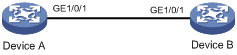
As shown in Figure 3,
· Device A and Device B are connected through their ports GigabitEthernet 1/0/1.
· Enable GVRP and configure the normal registration mode on ports to enable the registration and deregistration of dynamic and static VLAN information between the two devices.
Figure 3 Network diagram for GVRP normal registration mode configuration
Configuration procedure
1. Configure Device A
# Enable GVRP globally.
<DeviceA> system-view
[DeviceA] gvrp
# Configure port GigabitEthernet 1/0/1 as a trunk port, and assign it to all VLANs.
[DeviceA] interface gigabitethernet 1/0/1
[DeviceA-GigabitEthernet1/0/1] port link-type trunk
[DeviceA-GigabitEthernet1/0/1] port trunk permit vlan all
# Enable GVRP on trunk port GigabitEthernet 1/0/1.
[DeviceA-GigabitEthernet1/0/1] gvrp
[DeviceA-GigabitEthernet1/0/1] quit
# Create VLAN 2 (a static VLAN).
[DeviceA] vlan 2
[DeviceA-vlan2] quit
2. Configure Device B
# Enable GVRP globally.
<DeviceB> system-view
[DeviceB] gvrp
# Configure port GigabitEthernet 1/0/1 as a trunk port, and assign it to all VLANs.
[DeviceB] interface gigabitethernet 1/0/1
[DeviceB-GigabitEthernet1/0/1] port link-type trunk
[DeviceB-GigabitEthernet1/0/1] port trunk permit vlan all
# Enable GVRP on trunk port GigabitEthernet 1/0/1.
[DeviceB-GigabitEthernet1/0/1] gvrp
[DeviceB-GigabitEthernet1/0/1] quit
# Create VLAN 3 (a static VLAN).
[DeviceB] vlan 3
[DeviceB-vlan3] quit
3. Verify the configuration
Use the display gvrp local-vlan command to display the local VLAN information maintained by GVRP on ports. For example:
# Display the local VLAN information maintained by GVRP on port GigabitEthernet 1/0/1 of Device A.
[DeviceA] display gvrp local-vlan interface gigabitethernet 1/0/1
Following VLANs exist in GVRP local database:
1(default),2-3
According to the output, information about VLAN 1, static VLAN information of VLAN 2 on the local device, and dynamic VLAN information of VLAN 3 on Device B are all registered through GVRP.
# Display the local VLAN information maintained by GVRP on port GigabitEthernet 1/0/1 of Device B.
[DeviceB] display gvrp local-vlan interface gigabitethernet 1/0/1
Following VLANs exist in GVRP local database:
1(default),2-3
According to the output, information about VLAN 1, static VLAN information of VLAN 3 on the local device, and dynamic VLAN information of VLAN 2 on Device A are all registered through GVRP.
GVRP fixed registration mode configuration example
Network requirements
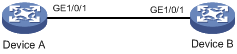
As shown in Figure 4,
· Device A and Device B are connected through their ports GigabitEthernet 1/0/1.
· Enable GVRP and configure the fixed registration mode on ports to enable the registration and deregistration of static VLAN information between the two devices.
Figure 4 Network diagram for GVRP fixed registration mode configuration
Configuration procedure
1. Configure Device A
# Enable GVRP globally.
<DeviceA> system-view
[DeviceA] gvrp
# Configure port GigabitEthernet 1/0/1 as a trunk port, and assign it to all VLANs.
[DeviceA] interface gigabitethernet 1/0/1
[DeviceA-GigabitEthernet1/0/1] port link-type trunk
[DeviceA-GigabitEthernet1/0/1] port trunk permit vlan all
# Enable GVRP on GigabitEthernet 1/0/1 and set the GVRP registration mode to fixed on the port.
[DeviceA-GigabitEthernet1/0/1] gvrp
[DeviceA-GigabitEthernet1/0/1] gvrp registration fixed
[DeviceA-GigabitEthernet1/0/1] quit
# Create VLAN 2 (a static VLAN).
[DeviceA] vlan 2
[DeviceA-vlan2] quit
2. Configure Device B
# Enable GVRP globally.
<DeviceB> system-view
[DeviceB] gvrp
# Configure port GigabitEthernet 1/0/1 as a trunk port, and assign it to all VLANs.
[DeviceB] interface gigabitethernet 1/0/1
[DeviceB-GigabitEthernet1/0/1] port link-type trunk
[DeviceB-GigabitEthernet1/0/1] port trunk permit vlan all
# Enable GVRP on GigabitEthernet 1/0/1, and set the GVRP registration mode to fixed on the port.
[DeviceB-GigabitEthernet1/0/1] gvrp
[DeviceB-GigabitEthernet1/0/1] gvrp registration fixed
[DeviceB-GigabitEthernet1/0/1] quit
# Create VLAN 3 (a static VLAN).
[DeviceB] vlan 3
[DeviceB-vlan3] quit
3. Verify the configuration
Use the display gvrp local-vlan command to display the local VLAN information maintained by GVRP on ports. For example:
# Display the local VLAN information maintained by GVRP on port GigabitEthernet 1/0/1 of Device A.
[DeviceA] display gvrp local-vlan interface gigabitethernet 1/0/1
Following VLANs exist in GVRP local database:
1(default), 2
According to the output, information about VLAN 1 and static VLAN information of VLAN 2 on the local device are registered through GVRP, but dynamic VLAN information of VLAN 3 on Device B is not.
# Display the local VLAN information maintained by GVRP on port GigabitEthernet 1/0/1 of Device B.
[DeviceB] display gvrp local-vlan interface gigabitethernet 1/0/1
Following VLANs exist in GVRP local database:
1(default), 3
According to the output, information about VLAN 1 and static VLAN information of VLAN 3 on the local device are registered through GVRP, but dynamic VLAN information of VLAN 2 on Device A is not.
GVRP forbidden registration mode configuration example
Network requirements
As shown in Figure 5,
· Device A and Device B are connected through their ports GigabitEthernet 1/0/1.
· Enable GVRP and configure the forbidden registration mode on ports to prevent the registration and deregistration of all VLANs but VLAN 1 between the two devices.
Figure 5 Network diagram for GVRP forbidden registration mode configuration
Configuration procedure
1. Configure Device A
# Enable GVRP globally.
<DeviceA> system-view
[DeviceA] gvrp
# Configure port GigabitEthernet 1/0/1 as a trunk port, and assign it to all VLANs.
[DeviceA] interface gigabitethernet 1/0/1
[DeviceA-GigabitEthernet1/0/1] port link-type trunk
[DeviceA-GigabitEthernet1/0/1] port trunk permit vlan all
# Enable GVRP on GigabitEthernet 1/0/1, and set the GVRP registration mode to forbidden on the port.
[DeviceA-GigabitEthernet1/0/1] gvrp
[DeviceA-GigabitEthernet1/0/1] gvrp registration forbidden
[DeviceA-GigabitEthernet1/0/1] quit
# Create VLAN 2 (a static VLAN).
[DeviceA] vlan 2
[DeviceA-vlan2] quit
2. Configure Device B
# Enable GVRP globally.
<DeviceB> system-view
[DeviceB] gvrp
# Configure port GigabitEthernet 1/0/1 as a trunk port, and assign it to all VLANs.
[DeviceB] interface gigabitethernet 1/0/1
[DeviceB-GigabitEthernet1/0/1] port link-type trunk
[DeviceB-GigabitEthernet1/0/1] port trunk permit vlan all
# Enable GVRP on GigabitEthernet 1/0/1, and set the GVRP registration mode to forbidden on the port.
[DeviceB-GigabitEthernet1/0/1] gvrp
[DeviceB-GigabitEthernet1/0/1] gvrp registration forbidden
[DeviceB-GigabitEthernet1/0/1] quit
# Create VLAN 3 (a static VLAN).
[DeviceB] vlan 3
[DeviceB-vlan3] quit
3. Verify the configuration
Use the display gvrp local-vlan command to display the local VLAN information maintained by GVRP on ports. For example:
# Display the local VLAN information maintained by GVRP on port GigabitEthernet 1/0/1 of Device A.
[DeviceA] display gvrp local-vlan interface gigabitethernet 1/0/1
Following VLANs exist in GVRP local database:
1(default)
According to the output, information about VLAN 1 is registered through GVRP, but static VLAN information of VLAN 2 on the local device and dynamic VLAN information of VLAN 3 on Device B are not.
# Display the local VLAN information maintained by GVRP on port GigabitEthernet 1/0/1 of Device B.
[DeviceB] display gvrp local-vlan interface gigabitethernet 1/0/1
Following VLANs exist in GVRP local database:
1(default)
According to the output, information about VLAN 1 is registered through GVRP, but static VLAN information of VLAN 3 on the local device and dynamic VLAN information of VLAN 2 on Device A are not.