- Table of Contents
-
- 03-Layer 2 Configuration Guide
- 00-Preface
- 01-Ethernet Interface Configuration
- 02-Loopback and Null Interface Configuration
- 03-VLAN Configuration
- 04-MAC Address Table Configuration
- 05-Ethernet Link Aggregation Configuration
- 06-Spanning Tree Configuration
- 07-Layer 2 Forwarding Configuration
- 08-PPPoE Configuration
- 09-FPGA Fast Forwarding Configuration
- 10-QinQ Termination Configuration
- Related Documents
-
| Title | Size | Download |
|---|---|---|
| 10-QinQ Termination Configuration | 118.14 KB |
Unambiguous QinQ termination configuration task list
Configuring unambiguous QinQ termination
Configuring the TPID value in SVLAN tags
QinQ termination configuration example
Configuring QinQ termination
Support for QinQ termination depends on the device model. For more information, see About the H3C Access Controllers Configuration Guides.
This document uses the following terms:
· CVLAN—Customer network VLANs, also called inner VLANs, refer to VLANs that a customer uses on the private network.
· SVLAN—Service provider network VLANs, also called outer VLANs, refer to VLANs that a service provider uses to transmit VLAN tagged traffic for customers.
Overview
QinQ termination terminates double-tagged or multiple-tagged packets whose outermost two layers of tags match the configured values or value ranges. Packets sent out of a QinQ termination-enabled interface are double-tagged.
Unambiguous QinQ termination terminates QinQ packets whose outermost two layers of VLAN IDs match the configured values. After receiving these packets, an unambiguous QinQ termination-enabled VLAN interface processes them as follows:
· Removes the two layers of VLAN tags of the packets.
· Tags the packets with two layers of VLAN tags as specified when sending them out.
Layer 2 Ethernet interfaces that are bound to the unambiguous QinQ termination-enabled VLAN interfaces operate as follows:
· Process only packets that match the unambiguous QinQ termination configuration of the VLAN interface.
· Drop any other packets sent to the VLAN interface.
Unambiguous QinQ termination configuration task list
|
Task |
Remarks |
|
Required. |
|
|
Optional. |
Configuring unambiguous QinQ termination
Before you configure unambiguous QinQ termination, disable Layer 2 fast forwarding, FPGA fast forwarding, and ARP snooping.
To configure unambiguous QinQ termination:
|
Step |
Command |
Remarks |
|
1. Enter system view. |
system-view |
N/A |
|
2. Enter VLAN interface view. |
interface vlan-interface interface-number |
N/A |
|
3. Configure unambiguous QinQ termination by specifying the Layer 2 VLAN ID. |
second-dot1q vlan-id |
By default, unambiguous QinQ termination is disabled. The Layer 1 VLAN ID of the VLAN-tagged packets that can be terminated by the VLAN interface is the number of the VLAN interface. This Layer 1 VLAN ID is not configurable. |
Configuring the TPID value in SVLAN tags
TPID identifies a frame as an 802.1Q tagged frame. The TPID value varies by vendor. On the device, the TPID in the 802.1Q tag added on a QinQ-enabled port is 0x8100 by default, in compliance with IEEE 802.1Q. In a multi-vendor network, make sure the TPID setting is the same across all devices, so 802.1Q tagged frames can be identified correctly.
A service provider-side port uses the SVLAN TPID to replace the TPID in outgoing frames' SVLAN tags and match incoming tagged frames. An incoming frame is handled as untagged if the TPID in its outer VLAN tag is different from the SVLAN TPID.
For example, the AC uses the TPID 0x8200, and it is connected to a provider device that uses the TPID 0x9100. To be compatible with the service provider device, you must set SVLAN TPID to 0x9100 on the AC, so the service provider device can identify 802.1Q tagged frames correctly.
The TPID field is in the same position as the EtherType field in an untagged Ethernet frame. To ensure correct packet type identification, do not set the TPID value to any of the reserved values listed in Table 1.
Table 1 Reserved protocol type values
|
Protocol type |
Value |
|
ARP |
0x0806 |
|
PUP |
0x0200 |
|
RARP |
0x8035 |
|
IP |
0x0800 |
|
IPv6 |
0x86DD |
|
PPPoE |
0x8863/0x8864 |
|
MPLS |
0x8847/0x8848 |
|
IPX/SPX |
0x8137 |
|
IS-IS |
0x8000 |
|
LACP |
0x8809 |
|
802.1X |
0x888E |
|
Cluster |
0x88A7 |
|
Reserved |
0xFFFD/0xFFFE/0xFFFF |
To set the TPID value in SVLAN tags:
|
Step |
Command |
Remarks |
|
1. Enter system view. |
system-view |
N/A |
|
2. Enter Layer 2 Ethernet interface view or Layer 2 aggregate interface view. |
interface interface-type interface-number |
Support for Layer 2 aggregate interfaces depends on the device model. For more information, see About the H3C Access Controllers Configuration Guides. |
|
3. Set the TPID value in SVLAN tags. |
qinq ethernet-type hex-value |
By default, the TPID is 0x8100. |
QinQ termination configuration example
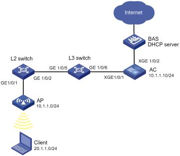
Network requirements
· Wireless clients access the Internet through the BAS.
· L2 switch and L3 switch tag the frames sent out of the wired port of the AP with CVLAN 1001 and SVLAN 100, respectively.
Configure unambiguous QinQ termination on the AC to terminate packets whose Layer 2 ID is 1001.
Specify SVLAN 200 and CVLAN 2001 for the client in radio binding, so that frames sent out of the client are tagged with SVLAN 200 and CVLAN 2001 when arriving at the BAS.
Configuration procedure
Configuring the L2 switch
# Create VLAN 1001.
<L2 switch> system-view
[L2 switch] vlan 1001
[L2 switch-vlan1001] quit
# Configure GigabitEthernet 1/0/1 as an access port and assign it to VLAN 1001.
[L2 switch] interface gigabitethernet 1/0/1
[L2 switch-GigabitEthernet1/0/1] port link-type access
[L2 switch-GigabitEthernet1/0/1] port access vlan 1001
[L2 switch-GigabitEthernet1/0/1] quit
# Configure GigabitEthernet 1/0/2 as a trunk port and assign it to VLAN 1001.
[L2 switch] interface gigabitethernet 1/0/2
[L2 switch-GigabitEthernet1/0/2] port link-type trunk
[L2 switch-GigabitEthernet1/0/2] port trunk permit vlan 1001
[L2 switch-GigabitEthernet1/0/2] quit
Configuring the L3 switch
# Create VLAN 100.
<L3 switch> system-view
[L3 switch] vlan 100
[L3 switch-vlan100] quit
# Configure GigabitEthernet 1/0/5 as an access port, and assign it to VLAN 100.
[L3 switch] interface gigabitethernet 1/0/5
[L3 switch-GigabitEthernet1/0/5] port link-type access
[L3 switch-GigabitEthernet1/0/5] port access vlan 100
# Enable basic QinQ on GigabitEthernet 1/0/5.
[L3 switch-GigabitEthernet1/0/5] qinq enable
[L3 switch-GigabitEthernet1/0/5] quit
# Configure GigabitEthernet 1/0/6 as a trunk port and assign it to VLAN 100.
[L3 switch] interface gigabitethernet 1/0/6
[L3 switch-GigabitEthernet1/0/6] port link-type trunk
[L3 switch-GigabitEthernet1/0/6] port trunk permit vlan 100
[L3 switch-GigabitEthernet1/0/6] quit
Configuring the AC
# Create VLANs 100, 1001, 200, and 2001.
<AC> system-view
[AC] vlan 100
[AC-vlan100] quit
[AC] vlan 1001
[AC-vlan1001] quit
[AC] vlan 200
[AC-vlan200] quit
[AC] vlan 2001
[AC-vlan2001] quit
# Configure Ten-GigabitEthernet 1/0/1 as a trunk port and assign it to VLANs 100 and 200.
[AC] interface ten-gigabitethernet 1/0/1
[AC-Ten-GigabitEthernet 1/0/1] port link-type trunk
[AC-Ten-GigabitEthernet 1/0/1] port trunk permit vlan 100 200
[AC-Ten-GigabitEthernet 1/0/1] quit
# Create VLAN-interface 100.
[AC] interface Vlan-interface 100
# Enable QinQ termination on VLAN-interface 100, and configure VLAN-interface 100 to terminate frames whose Layer 2 IDs are 1001.
[AC-Vlan-interface100] second-dot1q 1001
# Assign the IP address 10.1.1.10/24 to VLAN-interface 100.
[AC-Vlan-interface100] ip address 10.1.1.10 24
[AC-Vlan-interface100] quit
# Create a WLAN-ESS interface.
[AC] interface WLAN-ESS 1
[AC-WLAN-ESS1] quit
# Create a WLAN service template of the clear type and configure its SSID as ABC.
[AC]wlan service-template 1 clear
[AC-wlan-st-1] ssid ABC
# Bind interface WLAN-ESS 1 to the service template.
[AC-wlan-st-1] bind WLAN-ESS 1
# Enable the service template.
[AC-wlan-st-1] service-template enable
[AC-wlan-st-1] quit
# Create an AP template named ap1, set the AP model to WA2620-AGN, and set the AP serial ID to 210235A29DB099002291.
[AC] wlan ap ap1 model wa2620-agn
[AC-wlan-ap-ap1] serial-id 210235A29DB099002291
# Enter radio view of radio 1, and bind the service template and VLANs 200 and 2001 to the radio.
[AC-wlan-ap-ap1] radio 1
[AC-wlan-ap-ap1-radio-1] service-template 1 vlan-id 200 2001
[AC-wlan-ap-ap1-radio-1] radio enable
[AC-wlan-ap-ap1-radio-1] return
Configuring the BAS
# Create DHCP address pool 1, and specify subnet 10.1.1.0/24 for APs in the DHCP address pool.
<BAS> system-view
[BAS] dhcp server ip-pool 1
[BAS-dhcp-pool-1] network 10.1.1.0 mask 255.255.255.0
# Specify the gateway IP address as 10.1.1.1 for APs.
[BAS-dhcp-pool-1] gateway-list 10.1.1.1
[BAS-dhcp-pool-1] quit
# Enable DHCP.
[BAS] dhcp enable
# Configure QinQ termination on Ten-GigabitEthernet 0/0.100 to terminate frames whose SVLAN IDs are 100 and CVLAN IDs are 1001.
[BAS] interface ten-gigabitethernet0/0.100
[BAS-Ten-GigabitEthernet0/0.100] vlan-type dot1q vid 100 second-dot1q 1001
# Assign the IP address 10.1.1.1 to Ten-GigabitEthernet 0/0.100, so Ten-GigabitEthernet 0/0.100 acts as the gateway for APs.
[BAS-Ten-GigabitEthernet0/0.100] ip address 10.1.1.1 255.255.255.0
[BAS-Ten-GigabitEthernet0/0.100] quit
# Create DHCP address pool 2, and specify subnet 20.1.1.0/24 for clients in the DHCP address pool.
[BAS] dhcp server ip-pool 2
[BAS-dhcp-pool-2] network 20.1.1.0 mask 255.255.255.0
# Specify the gateway IP address as 20.1.1.1 for clients.
[BAS-dhcp-pool-2] gateway-list 20.1.1.1
[BAS-dhcp-pool-2] quit
# Configure QinQ termination on Ten-GigabitEthernet 0/0.200 to terminate frames whose SVLAN IDs are 200 and CVLAN IDs are 2001.
[BAS] interface ten-gigabitethernet0/0.200
[BAS-Ten-GigabitEthernet0/0.200] vlan-type dot1q vid 200 second-dot1q 2001
# Assign the IP address 20.1.1.1 to Ten-GigabitEthernet 0/0.200, so Ten-GigabitEthernet 0/0.200 acts as the gateway for clients.
[BAS-Ten-GigabitEthernet0/0.200] ip address 20.1.1.1 255.255.255.0
# Enable local proxy ARP on the BAS.
[BAS-Ten-GigabitEthernet0/0.200] local-proxy-arp enable
[BAS-Ten-GigabitEthernet0/0.200] quit
Verifying the configuration
# Verify the following:
· The AP gets an IP address on the network segment 10.1.1.0/24. Both the AP and AC can ping the BAS at 10.1.1.1.
· The AP associates with the AC successfully. When the ARP entry of the AP is deleted on the AC, the AC can successfully ping the AP.
· When the client log in, the client can get an IP address on the network segment 20.1.1.0/24. The client can ping the BAS at 20.1.1.1.
· When multiple clients log in, the clients can communicate with each other through the BAS.
(Details not shown.)