- Table of Contents
-
- 03-Layer 2 Configuration Guide
- 00-Preface
- 01-Ethernet Interface Configuration
- 02-Loopback and Null Interface Configuration
- 03-VLAN Configuration
- 04-MAC Address Table Configuration
- 05-Ethernet Link Aggregation Configuration
- 06-Spanning Tree Configuration
- 07-Layer 2 Forwarding Configuration
- 08-PPPoE Configuration
- 09-FPGA Fast Forwarding Configuration
- 10-QinQ Termination Configuration
- Related Documents
-
| Title | Size | Download |
|---|---|---|
| 05-Ethernet Link Aggregation Configuration | 206.33 KB |
Configuring Ethernet link aggregation
Aggregating links in static mode
Aggregating links in dynamic mode
Load sharing criteria for link aggregation groups
Configuration restrictions and guidelines
Ethernet link aggregation configuration task list
Configuring an aggregation group
Configuring a Layer 2 static aggregation group
Configuring a Layer 2 dynamic aggregation group
Configuring an aggregate interface
Configuring the description of an aggregate interface
Enabling link state traps for an aggregate interface
Shutting down an aggregate interface
Restoring the default settings for an aggregate interface
Configuring load sharing for link aggregation groups
Configuring the global link-aggregation load sharing criteria
Configuring group-specific load sharing criteria
Displaying and maintaining Ethernet link aggregation
Ethernet link aggregation configuration examples
Layer 2 static aggregation configuration example
Layer 2 dynamic aggregation configuration example
Configuring Ethernet link aggregation
Support for this feature depends on the device model. For more information, see About the H3C Access Controllers Configuration Guides.
Overview
Ethernet link aggregation, or simply link aggregation, combines multiple physical Ethernet ports into one logical link called an "aggregate link." Link aggregation delivers the following benefits:
· Increases bandwidth beyond the limits of any single link. In an aggregate link, traffic is distributed across the member ports.
· Improves link reliability. The member ports back up one another dynamically. When a member port fails, its traffic is switched automatically to other member ports.
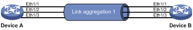
As shown in Figure 1, Device A and Device B are connected by three physical Ethernet links. These physical Ethernet links are combined into an aggregate link, Link Aggregation 1. The bandwidth of this aggregate link is as high as the total bandwidth of the three physical Ethernet links. At the same time, the three Ethernet links back up one another.
Figure 1 Ethernet link aggregation
Basic concepts
This section describes some basic link aggregation concepts.
Aggregation group, member port, and aggregate interface
Link aggregation is implemented by combining Ethernet interfaces into a link aggregation group. Each link aggregation group has one logical aggregate interface.
The rate of an aggregate interface equals the total rate of its member ports in Selected state, and its duplex mode is the same as the Selected member ports. For more information about the states of member ports in an aggregation group, see "Aggregation states of member ports in an aggregation group."
When you create an aggregate interface, the switch automatically creates an aggregation group of the same type and number as the aggregate interface. For example, when you create interface Bridge-Aggregation 1, Layer 2 aggregation group 1 is created automatically.
Only Layer 2 aggregate interfaces are supported. You can assign Layer 2 Ethernet interfaces only to a Layer 2 aggregation group.
Aggregation states of member ports in an aggregation group
A member port in an aggregation group can be in either of the following aggregation states:
· Selected—A Selected port can forward user traffic.
· Unselected—An Unselected port cannot forward user traffic.
When a Selected port fails, an Unselected port might become a Selected port and forward user traffic.
Operational key
When aggregating ports, the system automatically assigns each port an operational key based on port information such as port rate and duplex mode. Any change to this information triggers a recalculation of the operational key.
In an aggregation group, all Selected member ports are assigned the same operational key.
Configuration classes
Every configuration setting on a port might affect its aggregation state. Port configurations include the following classes:
· Port attribute configurations—Include port rate, duplex mode, and link status (up or down). These are the most basic port configurations.
· Class-two configurations—A member port can be placed in Selected state only if it has the same class-two configurations as the aggregate interface. Class-two configurations made on an aggregate interface are automatically synchronized to all its member ports. These configurations are retained on the member ports even after the aggregate interface is removed.
Table 1 Class-two configurations
|
Feature |
Considerations |
|
VLAN |
Permitted VLAN IDs, PVID, and link type (trunk, hybrid, or access). |
|
MAC address learning |
MAC address learning capability, MAC address learning limit, forwarding of frames with unknown destination MAC addresses after the MAC address learning limit is reached. |
|
|
NOTE: Any class-two configuration change might affect the aggregation state of link aggregation member ports and ongoing traffic. To be sure that you are aware of the risk, the system displays a warning message every time you try to change a class-two configuration setting on a member port. |
· Class-one configurations—Include settings that do not affect the aggregation state of the member port. Spanning tree settings are an example of class-one configurations. The class-one configuration of a member port is effective only when the member port leaves the aggregation group.
Reference port
When setting the aggregation state of the ports in an aggregation group, the system automatically picks a member port as the reference port. A Selected port must have the same port attributes and class-two configurations as the reference port. For information about how a reference port is chosen in a static link aggregation group, see "Choosing a reference port" in the section "Aggregating links in static mode."
Link aggregation modes
Link aggregation can be done in dynamic mode or static mode. Dynamic link aggregation uses the IEEE 802.3ad LACP, but static link aggregation does not. Table 2 compares the two aggregation modes.
Table 2 A comparison between static and dynamic aggregation modes
|
Aggregation mode |
LACP status on member ports |
Pros |
Cons |
|
Static |
Disabled |
Aggregation is stable. Peers do not affect the aggregation state of member ports. |
Member ports do not automatically align their aggregation state with their peer ports. The administrator must manually maintain link aggregations. |
|
Dynamic |
Enabled |
The peer systems maintain the aggregation state of member ports automatically. |
Aggregation is unstable. The aggregation state of member ports is susceptible to network changes. |
In a dynamic link aggregation group, a Selected port can receive and send LACPDUs. An Unselected port can receive and send LACPDUs only if it is up and has the same class-two configurations as the aggregate interface.
LACP
IEEE 802.3ad LACP enables dynamic aggregation of physical links. It uses LACPDUs for exchanging aggregation information between LACP-enabled devices.
1. LACP functions:
IEEE 802.3ad LACP offers basic LACP functions.
The basic LACP functions are implemented through the basic LACPDU fields, including the system LACP priority, system MAC address, port aggregation priority, port number, and operational key. Each member port in a LACP-enabled aggregation group exchanges the preceding information with its peer. When a member port receives an LACPDU, it compares the received information with the information received on other member ports. In this way, the two systems reach an agreement on which ports should be placed in Selected state.
2. LACP priorities:
LACP priorities have the following types: system LACP priority and port aggregation priority. The smaller the priority value, the higher the priority.
|
Type |
Description |
|
System LACP priority |
Used by two peer devices (or systems) to determine which one is superior in link aggregation. In dynamic link aggregation, the system with higher system LACP priority sets the Selected state of member ports on its side first, and then the system with lower priority sets the port state accordingly. |
|
Port aggregation priority |
Determines the likelihood of a member port to be Selected ports on a system. The higher the port aggregation priority, the higher the likelihood. |
3. LACP timeout interval:
LACP timeout interval specifies how long a member port waits to receive LACPDUs from the peer port. If a local member port fails to receive LACPDUs from the peer within three times the LACP timeout interval, the member port assumes that the peer port has failed. You can configure the LACP timeout interval as either the short timeout interval (1 second) or the long timeout interval (30 seconds).
Aggregating links in static mode
You must manually maintain the aggregation state of the member ports in a static aggregation group.
Choosing a reference port
The system chooses a reference port from the UP member ports that have the same class-two configurations as the aggregate interface.
The candidate ports are sorted by aggregation priority, duplex, and speed in the following order:
· Lowest aggregation priority value
· Full duplex/high speed
· Full duplex/low speed
· Half duplex/high speed
· Half duplex/low speed
The one at the top is chosen as the reference port. If two ports have the same aggregation priority, duplex mode, and speed, the one with the lower port number is chosen.
Setting the aggregation state of each member port
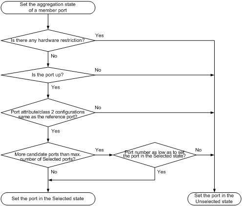
After choosing the reference port, the static aggregation group sets the aggregation state of each member port, as shown in Figure 2. After the static aggregation group has reached the limit on Selected ports, any port assigned to the group is placed in Unselected state to avoid traffic interruption on the current Selected ports.
Figure 2 Setting the aggregation state of a member port in a static aggregation group
Aggregating links in dynamic mode
LACP is automatically enabled on all member ports in a dynamic aggregation group. The protocol automatically maintains the aggregation state of ports.
Choosing a reference port
The local system (the actor) and the remote system (the partner) negotiate a reference port by using the following workflow:
1. The systems compare their system IDs (A system ID contains the system LACP priority and the system MAC address). The lower the LACP priority, the smaller the system ID. If LACP priority values are the same, the two systems compare their MAC addresses. The lower the MAC address, the smaller the system ID.
2. The system with the smaller system ID chooses the port with the smallest port ID as the reference port. A port ID contains a port priority and a port number. The port with the lower priority value is chosen. If two ports have the same aggregation priority, the system compares their port numbers. The port with the smaller port number is chosen.
Setting the aggregation state of each member port
After the reference port is chosen, the system with the lower system ID sets the state of each member port in the dynamic aggregation group on its side.
Figure 3 Setting the state of a member port in a dynamic aggregation group
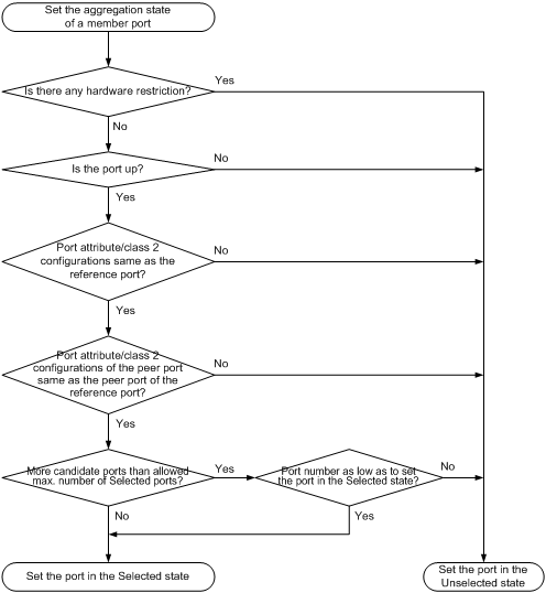
Meanwhile, the system with the higher system ID, which has identified the aggregation state changes on the remote system, sets the aggregation state of local member ports as the same as their peer ports.
When you aggregate interfaces in dynamic mode, follow these guidelines:
· A dynamic link aggregation group preferably sets full-duplex ports as the Selected ports, and will set one, and only one, half-duplex port as a Selected port when none of the full-duplex ports can be selected or only half-duplex ports exist in the group.
· To ensure stable aggregation and service continuity, do not change the port attribute configurations or class-two configurations on any member port.
· In a dynamic aggregation group, when the aggregation state of a local port changes, the aggregation state of its peer port also changes.
· The port assigned to the dynamic aggregation group after the Selected port limit has been reached is placed in Selected state if it is more eligible for being selected than a current member port.
Load sharing criteria for link aggregation groups
In a link aggregation group, traffic can be load-shared across the Selected member ports based on a set of criteria, depending on your configuration.
You can choose one or any combination of the following criteria for load sharing:
· Source/destination MAC addresses
· Source/destination IP addresses
Configuration restrictions and guidelines
When you configure a link aggregation group, follow these guidelines:
· To ensure stable aggregation state and service continuity, do not change port attributes or class-two configurations on any member port. If you must, make sure you understand its impact on the live network. Any port attribute or class-two configuration change might affect the aggregation state of link aggregation member ports and ongoing traffic.
· Avoid assigning ports to a static aggregation group that has reached the limit on Selected ports. These ports will be placed in Unselected state to avoid traffic interruption on the current Selected ports. However, a device reboot can cause the aggregation state of member ports to change.
Ethernet link aggregation configuration task list
|
Task |
Remarks |
|
Configuring an aggregation group: |
Required. |
|
Configuring an aggregate interface: · Configuring the description of an aggregate interface · Enabling link state traps for an aggregate interface |
Optional. |
|
Optional. |
Configuring an aggregation group
Configuring a Layer 2 static aggregation group
To guarantee a successful static aggregation, make sure the ports at both ends of each link are in the same aggregation state.
Removing an aggregate interface also removes its aggregation group. At the same time, all member ports leave the aggregation group.
To configure a Layer 2 static aggregation group:
|
Step |
Command |
Remarks |
|
1. Enter system view. |
system-view |
N/A |
|
2. Create a Layer 2 aggregate interface and enter Layer 2 aggregate interface view. |
interface bridge-aggregation interface-number |
When you create a Layer 2 aggregate interface, the system automatically creates a Layer 2 static aggregation group numbered the same. |
|
3. Exit to system view. |
quit |
N/A |
|
4. Assign a Layer 2 Ethernet interface to the aggregation group. |
a. interface interface-type interface-number b. port link-aggregation group number |
Repeat this step to assign more Layer 2 Ethernet interfaces to the aggregation group. |
|
5. Assign the port an aggregation priority. |
link-aggregation port-priority port-priority |
Optional. By default, the aggregation priority of a port is 32768. When the number of ports eligible for Selected ports exceeds the maximum number of Selected ports allowed in a static aggregation group, changing the aggregation priority of a port might affect the aggregation state of the ports in the static aggregation group. |
Configuring a Layer 2 dynamic aggregation group
To guarantee a successful dynamic aggregation, make sure the peer ports of the ports aggregated at one end are also aggregated. The two ends can automatically negotiate the aggregation state of each member port.
To configure a Layer 2 dynamic aggregation group:
|
Step |
Command |
Remarks |
|
1. Enter system view. |
system-view |
N/A |
|
2. Set the system LACP priority. |
lacp system-priority system-priority |
Optional. By default, the system LACP priority is 32768. Changing the system LACP priority might affect the aggregation state of the ports in a dynamic aggregation group. |
|
3. Create a Layer 2 aggregate interface and enter Layer 2 aggregate interface view. |
interface bridge-aggregation interface-number |
When you create a Layer 2 aggregate interface, the system automatically creates a Layer 2 static aggregation group numbered the same. |
|
4. Configure the aggregation group to operate in dynamic aggregation mode. |
link-aggregation mode dynamic |
By default, an aggregation group operates in static aggregation mode. |
|
5. Exit to system view. |
quit |
N/A |
|
6. Assign a Layer 2 Ethernet interface to the aggregation group. |
a. interface interface-type interface-number b. port link-aggregation group number |
Repeat this step to assign more Layer 2 Ethernet interfaces to the aggregation group. |
|
7. Assign the port an aggregation priority. |
link-aggregation port-priority port-priority |
Optional. By default, the aggregation priority of a port is 32768. When the number of ports eligible for Selected ports exceeds the maximum number of Selected ports allowed in a dynamic aggregation group, changing the aggregation priority of a port might affect the aggregation state of the ports in the dynamic aggregation group. |
|
8. Set the LACP timeout interval on the port to the short timeout interval (1 second). |
lacp period short |
Optional. By default, the LACP timeout interval on a port is the long timeout interval (30 seconds). |
Configuring an aggregate interface
Most of the configurations that can be performed on Layer 2 Ethernet interfaces can also be performed on Layer 2 aggregate interfaces.
Configuring the description of an aggregate interface
You can configure the description of an aggregate interface for administration purposes such as describing the purpose of the interface.
To configure the description of an aggregate interface:
|
Step |
Command |
Remarks |
|
1. Enter system view. |
system-view |
N/A |
|
2. Enter Layer 2 aggregate interface view. |
interface bridge-aggregation interface-number |
N/A |
|
3. Configure the description of the aggregate interface. |
description text |
Optional. By default, the description of an interface is in the format of interface-name Interface, such as Bridge-Aggregation1 Interface. |
Enabling link state traps for an aggregate interface
You can configure an aggregate interface to generate linkUp trap messages when its link goes up and linkDown trap messages when its link goes down. For more information, see Network Management and Monitoring Configuration Guide.
To enable link state traps on an aggregate interface:
|
Step |
Command |
Remarks |
|
1. Enter system view. |
system-view |
N/A |
|
2. Enable the trap function globally. |
snmp-agent trap enable [ standard [ linkdown | linkup ] * ] |
Optional. By default, link state trapping is enabled globally and on all interfaces. |
|
3. Enter Layer 2 aggregate interface view. |
interface bridge-aggregation interface-number |
N/A |
|
4. Enable link state traps for the aggregate interface. |
enable snmp trap updown |
Optional. Enabled by default. |
Shutting down an aggregate interface
Shutting down or bringing up an aggregate interface affects the aggregation state and link state of aggregated member ports in the following ways:
· When an aggregate interface is shut down, all Selected member ports become unselected and their link state becomes down.
· When an aggregate interface is brought up, the aggregation state of member ports is recalculated and their link state becomes up.
To shut down an aggregate interface:
|
Step |
Command |
Remarks |
|
1. Enter system view. |
system-view |
N/A |
|
2. Enter Layer 2 aggregate interface view. |
interface bridge-aggregation interface-number |
N/A |
|
3. Shut down the Layer 2 aggregate interface. |
shutdown |
By default, Layer 2 aggregate interfaces are up. |
Restoring the default settings for an aggregate interface
|
Step |
Command |
|
1. Enter system view. |
system-view |
|
2. Enter Layer 2 aggregate interface view. |
interface bridge-aggregation interface-number |
|
3. Restore the default settings for the aggregate interface. |
default |
Configuring load sharing for link aggregation groups
You can determine how traffic is load-shared in a link aggregation group by configuring load sharing criteria. The criteria can be source/destination MAC addresses or source/destination IP addresses carried in packets, or any combination. You can configure global or group-specific load sharing criteria. A link aggregation group preferentially uses the group-specific load sharing criteria. If no group-specific load sharing criteria is available, the group uses the global load sharing criteria.
Configuring the global link-aggregation load sharing criteria
|
Step |
Command |
Remarks |
|
1. Enter system view. |
system-view |
N/A |
|
2. Configure the global link-aggregation load sharing criteria. |
link-aggregation load-sharing mode { destination-ip | destination-mac | source-ip | source-mac } * |
The default setting is source and destination MAC addresses. |
Configuring group-specific load sharing criteria
|
Step |
Command |
Remarks |
|
1. Enter system view. |
system-view |
N/A |
|
2. Enter Layer 2 aggregate interface view. |
interface bridge-aggregation interface-number |
N/A |
|
3. Configure the load sharing criteria for the Layer 2 aggregation group. |
link-aggregation load-sharing mode { destination-ip | destination-mac | source-ip | source-mac } * |
The default setting is source and destination MAC addresses. |
Displaying and maintaining Ethernet link aggregation
|
Task |
Command |
Remarks |
|
Display information about Layer 2 aggregate interfaces. |
display interface [ bridge-aggregation ] [ brief [ down ] ] [ | { begin | exclude | include } regular-expression ] display interface bridge-aggregation interface-number [ brief ] [ | { begin | exclude | include } regular-expression ] |
Available in any view. |
|
Display the local system ID. |
display lacp system-id [ | { begin | exclude | include } regular-expression ] |
Available in any view. |
|
Display the global or group-specific link-aggregation load sharing criteria. |
display link-aggregation load-sharing mode [ interface [ bridge-aggregation interface-number ] ] [ | { begin | exclude | include } regular-expression ] |
Available in any view. |
|
Display detailed link aggregation information for link aggregation member ports. |
display link-aggregation member-port [ interface-list ] [ | { begin | exclude | include } regular-expression ] |
Available in any view. |
|
Display summary information about all aggregation groups. |
display link-aggregation summary [ | { begin | exclude | include } regular-expression ] |
Available in any view. |
|
Display detailed information about the specified aggregation groups. |
display link-aggregation verbose [ bridge-aggregation [ interface-number ] ] [ | { begin | exclude | include } regular-expression ] |
Available in any view. |
|
Clear LACP statistics for the specified link aggregation member ports. |
reset lacp statistics [ interface interface-list ] |
Available in any view. |
|
Clear statistics for the specified aggregate interfaces. |
reset counters interface [ bridge-aggregation [ interface-number ] ] |
Available in user view. |
Ethernet link aggregation configuration examples
In an aggregation group, only ports that have the same port attributes and class-two configurations (see "Configuration classes") as the reference port (see "Reference port") can operate as Selected ports. Make sure all member ports have the same port attributes and class-two configurations as the reference port. The other settings only need to be configured on the aggregate interface, not on the member ports.
|
|
NOTE: · ACs have either 10 GE or GE interfaces. Table 4 identifies the Ethernet interface on different types of ACs. · If the AC is an AC module installed on a switch, make sure the internal Ethernet interfaces that connect the switch to the AC module have correct settings, including in particular VLAN settings. |
Table 4 AC Ethernet interfaces
|
Hardware |
AC Ethernet interfaces |
|
AC modules (installed in a switch) |
|
|
LSQM1WCMD0 LSRM1WCM3A1 LSUM3WCMD0 LSUM1WCME0 |
The internal Ethernet interface that connects the AC module to the switch. |
|
Wireless switches |
|
|
WX3024E WX3010E |
The internal Ethernet interface that connects the AC engine to the switching engine. |
|
ACs |
|
|
WX6103 |
The internal Ethernet interface that connects the main control board to the switching board. |
|
WX5002V2 WX5004 WX3510E WX3540E WX5510E |
Any Ethernet interfaces on the AC. |
|
WX2540E WAC360 WAC361 |
Any LAN or WAN interfaces on the AC. |
|
WX5540E |
The internal Ethernet interface that connects the AC engine to the switching engine. |
Layer 2 static aggregation configuration example
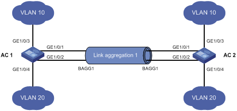
Network requirements
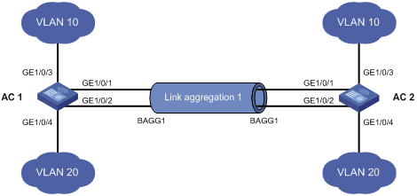
As shown in Figure 4, configure a Layer 2 static aggregation group on AC 1 and AC 2 respectively, enable VLAN 10 at one end of the aggregate link to communicate with VLAN 10 at the other end, and VLAN 20 at one end to communicate with VLAN 20 at the other end.
Enable traffic to be load-shared across aggregation group member ports based on the source and destination MAC addresses.
Configuration procedure
1. Configure AC 1:
# Create VLAN 10, and assign port GigabitEthernet 1/0/3 to VLAN 10.
<AC1> system-view
[AC1] vlan 10
[AC1-vlan10] port gigabitethernet 1/0/3
[AC1-vlan10] quit
# Create VLAN 20, and assign port GigabitEthernet 1/0/4 to VLAN 20.
[AC1] vlan 20
[AC1-vlan20] port gigabitethernet 1/0/4
[AC1-vlan20] quit
# Create Layer 2 aggregate interface Bridge-Aggregation 1.
[AC1] interface bridge-aggregation 1
[AC1-Bridge-Aggregation1] quit
# Assign ports GigabitEthernet 1/0/1 and GigabitEthernet 1/0/2 to link aggregation group 1.
[AC1] interface gigabitethernet 1/0/1
[AC1-GigabitEthernet1/0/1] port link-aggregation group 1
[AC1-GigabitEthernet1/0/1] quit
[AC1] interface gigabitethernet 1/0/2
[AC1-GigabitEthernet1/0/2] port link-aggregation group 1
[AC1-GigabitEthernet1/0/2] quit
# Configure Layer 2 aggregate interface Bridge-Aggregation 1 as a trunk port and assign it to VLANs 10 and 20.
[AC1] interface bridge-aggregation 1
[AC1-Bridge-Aggregation1] port link-type trunk
[AC1-Bridge-Aggregation1] port trunk permit vlan 10 20
Please wait... Done.
Configuring GigabitEthernet1/0/1... Done.
Configuring GigabitEthernet1/0/2... Done.
[AC1-Bridge-Aggregation1] quit
# Configure AC 1 to use the source and destination MAC addresses of packets as the global link-aggregation load sharing criteria.
[AC1] link-aggregation load-sharing mode source-mac destination-mac
2. Configure AC 2 in the same way AC 1 is configured. (Details not shown.)
Verifying the configuration
# Display summary information about all aggregation groups on AC 1.
[AC1] display link-aggregation summary
Aggregation Interface Type:
BAGG -- Bridge-Aggregation, RAGG -- Route-Aggregation
Loadsharing Type: Shar -- Loadsharing, NonS -- Non-Loadsharing
AGG Select Unselect Share
Interface Ports Ports Type
--------------------------------------------------------------------------------
BAGG1 2 0 Shar
The output shows that link aggregation group 1 is a load-shared Layer 2 static aggregation group and it contains two Selected ports.
# Display the global link-aggregation load sharing criteria on AC 1.
[AC1] display link-aggregation load-sharing mode
Link-Aggregation Load-Sharing Mode:
destination-mac address, source-mac address
The output shows that all link aggregation groups created on AC 1 perform load sharing based on source and destination MAC addresses.
Layer 2 dynamic aggregation configuration example
Network requirements
Configure a Layer 2 dynamic aggregation group on Device A and Device B (in Figure 5). Enable VLAN 10 at one end of the aggregate link to communicate with VLAN 10 at the other end, and VLAN 20 at one end to communicate with VLAN 20 at the other end.
Enable traffic to be load-shared across aggregation group member ports based on source and destination MAC addresses.
Configuration procedure
1. Configure Device A:
# Create VLAN 10, and assign the port GigabitEthernet 1/0/3 to VLAN 10.
<DeviceA> system-view
[DeviceA] vlan 10
[DeviceA-vlan10] port gigabitethernet 1/0/3
[DeviceA-vlan10] quit
# Create VLAN 20, and assign the port GigabitEthernet 1/0/4 to VLAN 20.
[DeviceA] vlan 20
[DeviceA-vlan20] port gigabitethernet 1/0/4
[DeviceA-vlan20] quit
# Create Layer 2 aggregate interface Bridge-Aggregation 1, and set the link aggregation mode to dynamic.
[DeviceA] interface bridge-aggregation 1
[DeviceA-Bridge-Aggregation1] link-aggregation mode dynamic
# Assign ports GigabitEthernet 1/0/1 and GigabitEthernet 1/0/2 to link aggregation group 1.
[DeviceA] interface gigabitethernet 1/0/1
[DeviceA-GigabitEthernet1/0/1] port link-aggregation group 1
[DeviceA-GigabitEthernet1/0/1] quit
[DeviceA] interface gigabitethernet 1/0/2
[DeviceA-GigabitEthernet1/0/2] port link-aggregation group 1
[DeviceA-GigabitEthernet1/0/2] quit
# Configure Layer 2 aggregate interface Bridge-Aggregation 1 as a trunk port and assign it to VLANs 10 and 20.
[DeviceA] interface bridge-aggregation 1
[DeviceA-Bridge-Aggregation1] port link-type trunk
[DeviceA-Bridge-Aggregation1] port trunk permit vlan 10 20
Please wait... Done.
Configuring GigabitEthernet1/0/1... Done.
Configuring GigabitEthernet1/0/2... Done.
[DeviceA-Bridge-Aggregation1] quit
# Configure the device to use the source and destination MAC addresses of packets as the global link-aggregation load sharing criteria.
[DeviceA] link-aggregation load-sharing mode source-mac destination-mac
2. Configure Device B in the same way Device A is configured. (Details not shown.)
Verifying the configuration
# Display summary information about all aggregation groups on Device A.
[DeviceA] display link-aggregation summary
Aggregation Interface Type:
BAGG -- Bridge-Aggregation, RAGG -- Route-Aggregation
Aggregation Mode: S -- Static, D -- Dynamic
Loadsharing Type: Shar -- Loadsharing, NonS -- Non-Loadsharing
Actor System ID: 0x8000, 000f-e2ff-0001
AGG AGG Partner ID Select Unselect Share
Interface Mode Ports Ports Type
-------------------------------------------------------------------------------
BAGG1 D 0x8000, 000f-e2ff-0002 2 0 Shar
The output shows that link aggregation group 1 is a load-shared Layer 2 dynamic aggregation group, and it contains two Selected ports.
# Display the global link-aggregation load sharing criteria on Device A.
[DeviceA] display link-aggregation load-sharing mode
Link-Aggregation Load-Sharing Mode:
destination-mac address, source-mac address
The output shows that all link aggregation groups created on the device perform load sharing based on source and destination MAC addresses.