- Table of Contents
-
- 03-Layer 2 Configuration Guide
- 00-Preface
- 01-Ethernet Interface Configuration
- 02-Loopback and Null Interface Configuration
- 03-VLAN Configuration
- 04-MAC Address Table Configuration
- 05-Ethernet Link Aggregation Configuration
- 06-Spanning Tree Configuration
- 07-Layer 2 Forwarding Configuration
- 08-PPPoE Configuration
- 09-FPGA Fast Forwarding Configuration
- 10-QinQ Termination Configuration
- Related Documents
-
| Title | Size | Download |
|---|---|---|
| 03-VLAN Configuration | 211.07 KB |
Configuring basic VLAN settings
Configuration restrictions and guidelines
Configuring basic settings of a VLAN interface
VLAN interface configuration example
Introduction to port-based VLAN
Assigning an access port to a VLAN
Assigning a trunk port to a VLAN
Assigning a hybrid port to a VLAN
Port-based VLAN configuration example
Introduction to MAC-based VLAN
Configuration restrictions and guidelines
MAC-based VLAN configuration example
Displaying and maintaining VLAN
Configuring VLANs
Overview
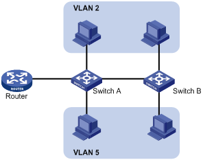
Ethernet is a shared-media network based on the CSMA/CD mechanism. A LAN built by using Ethernet is both a collision domain and a broadcast domain. In a LAN with plenty of hosts, the LAN might be full of collisions and broadcasts. As a result, the LAN performance is degraded or the LAN becomes unavailable. You can deploy bridges or Layer 2 switches in the LAN to reduce collisions, but this cannot confine broadcasts. To address the issue, virtual LAN (VLAN) was introduced to break a LAN down into separate VLANs. Hosts in the same VLAN can directly communicate, and hosts of different VLANs cannot directly communicate. For example, hosts in VLAN 2 can communicate with each other, but cannot communicate with the hosts in VLAN 5. A VLAN is a broadcast domain, and contains all broadcast traffic within it, as shown in Figure 1.
A VLAN is logically divided on an organizational basis rather than on a physical basis. For example, using VLAN, all workstations and servers that a particular workgroup uses can be assigned to the same VLAN, regardless of their physical locations.
VLAN technology delivers the following benefits:
· Confining broadcast traffic within individual VLANs. This reduces bandwidth waste and improves network performance.
· Improving LAN security. By assigning user groups to different VLANs, you can isolate them at Layer 2. To enable communication between VLANs, routers or Layer 3 switches are required.
· Creating flexible virtual workgroups. Because users from the same workgroup can be assigned to the same VLAN regardless of their physical locations, network construction and maintenance are much easier and more flexible.
VLAN frame encapsulation
In order that a network device can identify frames of different VLANs, a VLAN tag field is inserted into the data link layer encapsulation.
The format of VLAN-tagged frames is defined in IEEE 802.1Q issued in 1999.
As shown in Figure 2, in the header of a traditional Ethernet data frame, the field after the destination MAC address and the source MAC address (DA & SA) field is the Type field, which indicates the upper layer protocol type.
Figure 2 Traditional Ethernet frame format
![]()
IEEE 802.1Q inserts a four-byte VLAN tag between the DA & SA field and the Type field to identify the VLAN information, as shown in Figure 3.
Figure 3 Position and format of VLAN tag
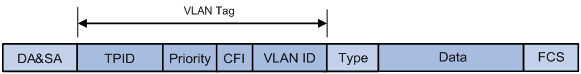
The fields of a VLAN tag are as follows:
· TPID—The 16-bit TPID field indicates whether a frame is VLAN-tagged. By default, the TPID value is 0x8100, which indicates that the frame is VLAN-tagged. Devices vendors can set the TPID to different values. For compatibility with these devices, modify the TPID value so that frames carry a TPID value identical to the value of a particular vendor, allowing interoperability with devices from that vendor. The device determines whether a received frame carries a VLAN tag by checking the TPID value. When the TPID value of a frame is the configured value or 0x8100, the frame is considered as a VLAN-tagged frame.
· Priority—The 3-bit priority field indicates the 802.1p priority of the frame. For more information, see ACL and QoS Configuration Guide.
· CFI—The 1-bit CFI field indicates whether the MAC addresses are encapsulated in standard format when packets are transmitted across different media. A value of 0 indicates that MAC addresses are encapsulated in standard format. A value of 1 indicates that MAC addresses are encapsulated in a non-standard format. The value of this field is 0 by default.
· VLAN ID—The 12-bit VLAN ID field identifies the VLAN that the frame belongs to. The VLAN ID range is 0 to 4095. Because 0 and 4095 are reserved, user-configurable VLAN IDs are in the range of 1 to 4094.
A network device handles an incoming frame depending on whether the frame is VLAN tagged and the value of the VLAN tag, if any. For more information, see "Introduction to port-based VLAN."
Ethernet supports encapsulation formats Ethernet II, 802.3/802.2 LLC, 802.3/802.2 SNAP, and 802.3 raw. The Ethernet II encapsulation format is used here. For how the VLAN tag fields are added to frames encapsulated in these formats for VLAN identification, see related protocols and standards.
When a frame carrying multiple VLAN tags passes through, the device processes the frame according to its outer VLAN tag, and transmits the inner tags as payload.
VLAN types
You can implement VLANs based on the following criteria:
· Port
· MAC address
· Protocol
· IP subnet
· Policy
· Other criteria
The device supports port-based VLAN and MAC-based VLAN. This chapter covers port-based VLAN and MAC-based VLAN.
You can configure the two types of VLANs on a port at the same time. When the device is determining which VLAN a packet that passes through the port should be assigned to, it looks up VLANs in the default order of MAC-based VLAN and port-based VLAN.
Protocols and standards
IEEE 802.1Q, IEEE Standards for Local and Metropolitan Area Networks: Virtual Bridged Local Area Networks
Configuring basic VLAN settings
Configuration restrictions and guidelines
· As the default VLAN, VLAN 1 cannot be created or removed.
· You cannot manually create or remove VLANs reserved for special purposes.
· To remove a protocol reserved VLAN, management VLAN, dynamic VLAN, and VLAN with a QoS policy applied, remove the configuration from the VLAN first, and execute the undo vlan command.
· You can configure broadcast suppression to limit the size of broadcast traffic permitted to pass through a VLAN. When the broadcast traffic exceeds the upper threshold, the exceeding broadcast traffic will be dropped.
Configuration procedure
To configure basic VLAN settings:
|
Step |
Command |
Remarks |
|
1. Enter system view. |
system-view |
N/A |
|
2. Create a VLAN and enter its view, or create VLANs in batch. |
vlan { vlan-id1 [ to vlan-id2 ] | all } |
Optional. By default, only the default VLAN (VLAN 1) exists in the system. |
|
3. Enter VLAN view. |
vlan vlan-id |
Required only when you create VLANs in bulk. |
|
4. Configure a name for the VLAN. |
name text |
Optional. The default name is VLAN vlan-id, which is the ID of the VLAN. For example, the name of VLAN 100 is VLAN 0100 by default. |
|
5. Configure a description for the VLAN. |
description text |
Optional. The default description is VLAN vlan-id, which is the ID of the VLAN. For example, the description of VLAN 100 is VLAN 0100 by default. |
Configuring basic settings of a VLAN interface
You can use VLAN interfaces to provide Layer 3 communication between hosts of different VLANs. VLAN interfaces are virtual interfaces used for Layer 3 communication between different VLANs. They do not exist as physical entities on devices. For each VLAN, you can create one VLAN interface. You can assign the VLAN interface an IP address and specify the IP address as the gateway address for the devices in the VLAN, so that traffic can be routed to other IP subnets.
Configuration procedure
Before you create a VLAN interface for a VLAN, make sure the VLAN already exists.
To configure basic settings of a VLAN interface:
|
Step |
Command |
Remarks |
|
1. Enter system view. |
system-view |
N/A |
|
2. Create a VLAN interface and enter VLAN interface view. |
interface vlan-interface vlan-interface-id |
If the specified VLAN interface already exists, you enter its view directly. |
|
3. Assign an IP address to the VLAN interface. |
ip address ip-address { mask | mask-length } [ sub ] |
Optional. By default, no IP address is assigned to any VLAN interface. |
|
4. Configure the description of the VLAN interface. |
description text |
Optional. By default, the description of a VLAN is the VLAN interface name. For example, Vlan-interface1 Interface. |
|
5. Set the MTU for the VLAN interface. |
mtu size |
Optional. By default, the MTU is 1500 bytes. |
|
6. Restore the default settings for the VLAN interface. |
default |
Optional. |
|
7. Cancel the action of manually shutting down the VLAN interface. |
undo shutdown |
Optional. By default, a VLAN interface is not manually shut down. The VLAN interface is up if one or more ports in the VLAN is up, and goes down if all ports in the VLAN go down. |
VLAN interface configuration example
ACs have either 10 GE or GE interfaces. Table 1 identifies the Ethernet interfaces on different types of ACs.
If the AC is an AC module installed on a switch, make sure the internal Ethernet interface that connects the switch to the AC module has correct settings, including in particular VLAN settings.
Table 1 AC Ethernet interfaces
|
Hardware |
AC Ethernet interfaces |
|
AC modules (installed in a switch) |
|
|
LSQM1WCMD0 LSRM1WCM3A1 LSUM3WCMD0 |
The internal Ethernet interface that connects the AC module to the switch. |
|
Wireless switches |
|
|
WX3024E WX3010E |
The internal Ethernet interface that connects the AC engine to the switching engine. |
|
ACs |
|
|
WX6103 |
The internal Ethernet interface that connects the main control board to the switching board. |
|
WX3510E WX3540E WX5002V2 WX5004 WX5510E |
Any Ethernet interfaces on the AC. |
|
WX2540E WAC360 WAC361 |
Any LAN or WAN interfaces on the AC. |
|
WX5540E |
The internal Ethernet interface that connects the AC engine to the switching engine. |
Network requirements
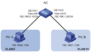
As shown in Figure 4, PC A is assigned to VLAN 5. PC B is assigned to VLAN 10. The PCs belong to different IP subnets and cannot communicate with each other.
Configure VLAN interfaces on the AC and configure the PCs to enable Layer 3 communication between the PCs.
Configuration procedure
1. Configure the AC:
# Create VLAN 5 and assign GigabitEthernet 1/0/1 to it.
<AC> system-view
[AC] vlan 5
[AC-vlan5] port gigabitethernet 1/0/1
# Create VLAN 10 and assign GigabitEthernet 1/0/2 to it.
[AC-vlan5] vlan 10
[AC-vlan10] port gigabitethernet 1/0/2
[AC-vlan10] quit
# Create VLAN-interface 5 and configure its IP address as 192.168.0.10/24.
[AC] interface vlan-interface 5
[AC-Vlan-interface5] ip address 192.168.0.10 24
[AC-Vlan-interface5] quit
# Create VLAN-interface 10 and configure its IP address as 192.168.1.20/24.
[AC] interface vlan-interface 10
[AC-Vlan-interface10] ip address 192.168.1.20 24
[AC-Vlan-interface10] return
2. Configure the default gateway of PC A as 192.168.0.10.
3. Configure the default gateway of PC B as 192.168.1.20.
Verifying the configuration
1. The PCs can ping each other.
2. Display brief information about Layer 3 interfaces on the AC to verify the configuration.
<AC> display ip interface brief
*down: administratively down
(s): spoofing (l): loopback
Interface Physical Protocol IP Address Description
M-GE1/0/0 up up -- --
Vlan5 up up 192.168.0.10 Vlan-inte...
Vlan10 up up 192.168.1.20 Vlan-inte...
Configuring port-based VLANs
Introduction to port-based VLAN
Port-based VLANs group VLAN members by port. A port forwards traffic for a VLAN only after it is assigned to the VLAN.
Port link type
You can configure the link type of a port as access, trunk, or hybrid. The link types use the following VLAN tag handling methods:
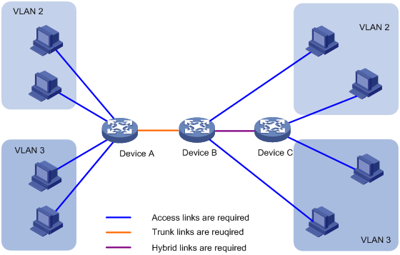
· Access port—Belongs to only one VLAN and sends traffic untagged. Access ports are usually used to connect a terminal device unable to identify VLAN-tagged packets, or are used when separating different VLAN members is unnecessary. As shown in Figure 5, Device A is connected to common PCs that cannot recognize VLAN-tagged packets, and you must configure Device A's ports that connect to the PCs as access ports.
· Trunk port—Carries multiple VLANs to receive and send traffic for them. Except for traffic from the port VLAN ID (PVID), traffic sent through a trunk port will be VLAN-tagged. Usually, ports that connect network devices are configured as trunk ports. As shown in Figure 5, Device A and Device B need to transmit packets of VLAN 2 and VLAN 3, and you must configure the ports interconnecting Device A and Device B as trunk ports and assign them to VLAN 2 and VLAN 3.
· Hybrid port—A hybrid port allows traffic of some VLANs to pass through untagged and traffic of other VLANs to pass through tagged. Usually, hybrid ports are configured to connect devices whose support for VLAN-tagged packets you are uncertain about. As shown in Figure 5, Device C connects to a small-sized LAN in which some PCs belong to VLAN 2 and other PCs belong to VLAN 3, and Device B is uncertain about whether Device C supports VLAN-tagged packets. On Device B, configure the port connecting to Device C as a hybrid port to allow packets from VLAN 2 and VLAN 3 to pass through untagged.
PVID
By default, VLAN 1 is the port VLAN ID (PVID) for all ports. You can configure the PVID for a port as required.
When you configure the PVID on a port, use the following guidelines:
· An access port can join only one VLAN. The VLAN to which the access port belongs is the PVID of the port.
· A trunk or hybrid port can join multiple VLANs, and you can configure a PVID for the port.
· You can use a nonexistent VLAN as the PVID for a hybrid or trunk port, but not for an access port. After you use the undo vlan command to remove the VLAN where an access port resides, the PVID of the port changes to VLAN 1. The removal of the VLAN specified as the PVID of a trunk or hybrid port, however, does not affect the PVID setting on the port.
· H3C recommends setting the same PVID for local and remote ports.
· Make sure a port permits the traffic from its PVID to pass through. Otherwise, when the port receives frames tagged with the PVID or untagged frames, the port drops these frames.
Frame handling on a port
The following table shows how ports of different link types handle frames:
|
Actions |
Access |
Trunk |
Hybrid |
|
|
Incoming untagged frame |
Tags the frame with the PVID tag. |
Determines whether the PVID is permitted on the port, as follows: · If yes, tags the frame with the PVID tag. · If not, drops the frame. |
||
|
Incoming tagged frame |
· Receives the frame if its VLAN ID is the same as the PVID. · Drops the frame if its VLAN ID is different from the PVID. |
· Receives the frame if its VLAN is permitted on the port. · Drops the frame if its VLAN is not permitted on the port. |
||
|
Outgoing frames |
Removes the VLAN tag and sends the frame. |
· Removes the tag and sends the frame if the frame carries the PVID tag and the port belongs to the PVID. · Sends the frame without removing the tag if its VLAN is carried on the port but is different from the PVID. |
Sends the frame if its VLAN is permitted on the port. The frame is sent with the VLAN tag removed or intact depending on your configuration with the port hybrid vlan command. This is true of the PVID. |
|
Assigning an access port to a VLAN
You can assign an access port to a VLAN in VLAN view or interface view. Before you assign an access port to a VLAN, create the VLAN.
In VLAN view, you can assign only Layer 2 Ethernet interfaces to the VLAN.
To assign one or multiple access ports to a VLAN in VLAN view:
|
Step |
Command |
Remarks |
|
1. Enter system view. |
system-view |
N/A |
|
2. Enter VLAN view. |
vlan vlan-id |
N/A |
|
3. Assign one or a group of access ports to the VLAN. |
port interface-list |
By default, all ports belong to VLAN 1. |
To assign an access port to a VLAN in interface view:
|
Step |
Command |
Remarks |
|
1. Enter system view. |
system-view |
N/A |
|
2. Enter interface view or port group view. |
· Enter Layer 2 Ethernet interface view: · Enter Layer 2 aggregate interface view: · Enter port group view: |
· The configuration made in WLAN-ESS interface view or Layer 2 Ethernet interface view applies only to the port. · The configuration made in port group view applies to all ports in the port group. · The configuration made in Layer 2 aggregate interface view applies to the aggregate interface and its aggregation member ports. If the system fails to apply the configuration to the aggregate interface, it stops applying the configuration to aggregation member ports. If the system fails to apply the configuration to an aggregation member port, it skips the port and moves to the next member port. |
|
3. Configure the link type of the ports as access. |
port link-type access |
Optional. By default, all ports are access ports. |
|
4. Assign the access ports to a VLAN. |
port access vlan vlan-id |
Optional. By default, all access ports belong to VLAN 1. |
Assigning a trunk port to a VLAN
A trunk port can carry multiple VLANs. You can assign it to a VLAN in interface view.
To assign a trunk port to one or multiple VLANs:
|
Step |
Command |
Remarks |
|
1. Enter system view. |
system-view |
N/A |
|
2. Enter interface view or port group view. |
· Enter Layer 2 Ethernet interface view: · Enter Layer 2 aggregate interface view: · Enter port group view: |
· The configuration made in Ethernet interface view applies only to the port. · The configuration made in port group view applies to all ports in the port group. · The configuration made in Layer 2 aggregate interface view applies to the aggregate interface and its aggregation member ports. If the system fails to apply the configuration to the aggregate interface, it stops applying the configuration to aggregation member ports. If the system fails to apply the configuration to an aggregation member port, it skips the port and moves to the next member port. |
|
3. Configure the link type of the ports as trunk. |
port link-type trunk |
By default, all ports are access ports. |
|
4. Assign the trunk ports to the specified VLANs. |
port trunk permit vlan { vlan-list | all } |
By default, a trunk port carries only VLAN 1. |
|
5. Configure the PVID of the trunk ports. |
port trunk pvid vlan vlan-id |
Optional. By default, the PVID is VLAN 1. |
To change the link type of a port from trunk to hybrid or from hybrid to trunk, you must set the link type to access first.
After configuring the PVID for a trunk port, you must use the port trunk permit vlan command to configure the trunk port to allow packets from the PVID to pass through.
Assigning a hybrid port to a VLAN
A hybrid port can carry multiple VLANs. You can assign it to a VLAN in interface view. Before assigning a hybrid port to a VLAN, create the VLAN first.
To assign a hybrid port to one or multiple VLANs:
|
Step |
Command |
Remarks |
|
1. Enter system view. |
system-view |
N/A |
|
2. Enter interface view or port group view. |
· Enter Layer 2 Ethernet interface view: · Enter Layer 2 aggregate interface view: · Enter port group view: |
· The configuration made in Ethernet or WLAN-ESS interface view applies only to the port. · The configuration made in port group view applies to all ports in the port group. · The configuration made in Layer 2 aggregate interface view applies to the aggregate interface and its aggregation member ports. If the system fails to apply the configuration to the aggregate interface, it stops applying the configuration to aggregation member ports. If the system fails to apply the configuration to an aggregation member port, it skips the port and moves to the next member port. |
|
3. Configure the link type of the ports as hybrid. |
port link-type hybrid |
By default, all ports are access ports. |
|
4. Assign the hybrid ports to the specified VLANs. |
port hybrid vlan vlan-list { tagged | untagged } |
By default, a hybrid port allows only packets of VLAN 1 to pass through untagged. |
|
5. Configure the PVID of the hybrid ports. |
port hybrid pvid vlan vlan-id |
Optional. By default, the PVID is VLAN 1. |
To change the link type of a port from trunk to hybrid or from hybrid to trunk, you must set the link type to access first.
After you configure the PVID for a hybrid port, you must use the port hybrid vlan command to configure the hybrid port to allow packets from the PVID to pass through.
Port-based VLAN configuration example
ACs have either 10 GE or GE interfaces. Table 2 identifies the Ethernet interfaces on different types of ACs.
If the AC is an AC module installed on a switch, make sure the internal Ethernet interface that connects the switch to the AC module has correct settings, including in particular VLAN settings.
Table 2 AC Ethernet interfaces
|
Hardware |
AC Ethernet interfaces |
|
AC modules (installed in a switch) |
|
|
LSQM1WCMD0 LSRM1WCM3A1 LSUM3WCMD0 |
The internal Ethernet interface that connects the AC module to the switch. |
|
Wireless switches |
|
|
WX3024E WX3010E |
The internal Ethernet interface that connects the AC engine to the switching engine. |
|
ACs |
|
|
WX6103 |
The internal Ethernet interface that connects the main control board to the switching board. |
|
WX3510E WX3540E WX5002V2 WX5004 WX5510E |
Any Ethernet interfaces on the AC. |
|
WX2540E WAC360 WAC361 |
Any LAN or WAN interfaces on the AC. |
|
WX5540E |
The internal Ethernet interface that connects the AC engine to the switching engine. |
Network requirements
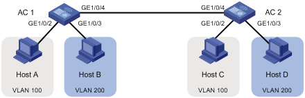
As shown in Figure 6:
· Host A and Host C belong to Department A, and access the enterprise network through different devices. Host B and Host D belong to Department B, and access the enterprise network through different devices.
· To ensure communication security and avoid broadcast storms, VLANs are configured in the enterprise network to isolate Layer 2 traffic of different departments. VLAN 100 is assigned to Department A, and VLAN 200 is assigned to Department B.
· Make sure that hosts within the same VLAN can communicate with each other. Host A can communicate with Host C, and Host B can communicate with Host D.
Configuration procedure
1. Configure AC 1:
# Create VLAN 100, and assign port GigabitEthernet 1/0/2 to VLAN 100.
<AC1> system-view
[AC1] vlan 100
[AC1-vlan100] port gigabitethernet 1/0/2
[AC1-vlan100] quit
# Create VLAN 200, and assign port GigabitEthernet 1/0/3 to VLAN 200.
[AC1] vlan 200
[AC1-vlan200] port gigabitethernet 1/0/3
[AC1-vlan200] quit
# Configure port GigabitEthernet 1/0/4 as a trunk port, and assign it to VLANs 100 and 200, enabling GigabitEthernet 1/0/4 to forward traffic of VLANs 100 and 200 to AC 2.
[AC1] interface gigabitethernet 1/0/4
[AC1-GigabitEthernet1/0/4] port link-type trunk
[AC1-GigabitEthernet1/0/4] port trunk permit vlan 100 200
Please wait... Done.
2. Configure AC 2 in the same way AC 1 is configured.
3. Configure Host A and Host C to be on the same IP subnet, for example, 192.168.100.0/24. Configure Host B and Host D to be on the same IP subnet, for example, 192.168.200.0/24.
Verifying the configuration
1. Host A and Host C can ping each other successfully, but they both fail to ping Host B. Host B and Host D can ping each other successfully, but they both fail to ping Host A.
2. Check whether the configuration is successful by displaying relevant VLAN information:
# Display information about VLANs 100 and 200 on AC 1.
[AC1-GigabitEthernet1/0/4] display vlan 100
VLAN ID: 100
VLAN Type: static
Route Interface: not configured
Description: VLAN 0100
Name: VLAN 0100
Broadcast MAX-ratio: 100%
Tagged Ports:
GigabitEthernet1/0/4
Untagged Ports:
GigabitEthernet1/0/2
[AC1-GigabitEthernet1/0/4] display vlan 200
VLAN ID: 200
VLAN Type: static
Route Interface: not configured
Description: VLAN 0200
Name: VLAN 0200
Broadcast MAX-ratio: 100%
Tagged Ports:
GigabitEthernet1/0/4
Untagged Ports:
GigabitEthernet1/0/3
Configuring MAC-based VLANs
Introduction to MAC-based VLAN
The MAC-based VLAN feature assigns hosts to a VLAN based on their MAC addresses. This feature is usually used in conjunction with security technologies such as 802.1X to provide secure, flexible network access for terminal devices.
Static MAC-based VLAN assignment
Static MAC-based VLAN assignment applies to networks containing a small number of VLAN users. In such a network, you can create a MAC address-to-VLAN map containing multiple MAC address-to-VLAN entries on a port, enable the MAC-based VLAN feature on the port, and assign the port to MAC-based VLANs.
With static MAC-based VLAN assignment configured on a port, the device processes received frames by using the following guidelines:
· When the port receives an untagged frame, the device looks up the MAC address-to-VLAN map based on the source MAC address of the frame for a match.
¡ The device first performs a fuzzy match. In the fuzzy match, the device searches the MAC address-to-VLAN entries whose masks are not all-Fs and performs a logical AND operation on the source MAC address and each mask. If the result of an AND operation matches the corresponding MAC address, the device tags the frame with the corresponding VLAN ID.
¡ If the fuzzy match fails, the device performs an exact match. In the exact match, the device searches the MAC address-to-VLAN entries whose masks are all-Fs. If the MAC address of a MAC address-to-VLAN entry matches the source MAC address of the untagged frame, the device tags the frame with the corresponding VLAN ID.
¡ When a frame that matches the MAC address-to-VLAN entry is forwarded, the forwarding policy for the frame is determined by the priority of the MAC-based VLAN (the 802.1p priority of the VLAN corresponding to the MAC address).
¡ If no match is found, the device assigns a VLAN to the frame by using other criteria, such as IP subnet or protocol, and forwards the frame.
¡ If no VLAN is available, the device tags the frame with the PVID of the receiving port and forwards the frame.
· When the port receives a tagged frame, the port forwards the frame if the VLAN ID of the frame is permitted by the port, and otherwise it drops the frame.
When you configure static MAC-based VLAN assignment, follow these guidelines:
· When a port is assigned to the corresponding VLAN in a MAC address-to-VLAN entry, but has not been assigned to the VLAN by using the port hybrid vlan command, the port sends packets from the VLAN with VLAN tags removed.
· When a packet matches a MAC address-to-VLAN entry, the device picks a forwarding policy for the packet according to the 802.1p priority mapped to the MAC address.
Dynamic MAC-based VLAN
You can use dynamic MAC-based VLAN with access authentication (such as 802.1X authentication based on MAC addresses) to implement secure, flexible terminal access. After configuring dynamic MAC-based VLAN on the device, you must configure the username-to-VLAN entries on the access authentication server.
When a user passes authentication of the access authentication server, the device obtains VLAN information from the server, generates a MAC address-to-VLAN entry by using the source MAC address of the user packet and the VLAN information, and assigns the port to the MAC-based VLAN. When the user goes offline, the device automatically deletes the MAC address-to-VLAN entry, and removes the port from the MAC-based VLAN. For more information about 802.1X, MAC, and portal authentication, see Security Configuration Guide.
Configuration restrictions and guidelines
The following guidelines apply for MAC-based VLAN configuration:
· MAC-based VLANs are available only on hybrid ports.
· The MAC-based VLAN feature is mainly configured on downlink ports of user access devices. Do not enable this function together with link aggregation.
Configuration procedure
To configure static MAC-based VLAN assignment:
|
Step |
Command |
Remarks |
|
1. Enter system view. |
system-view |
N/A |
|
2. Associate a specific MAC address with a VLAN. |
mac-vlan mac-address mac-address [ mask mac-mask ] vlan vlan-id [ priority priority ] |
N/A |
|
3. Enter interface view or port group view. |
· Enter interface view: · Enter port group view: |
· The configuration made in Ethernet interface or WLAN-ESS interface view applies only to the port. · The configuration made in port group view applies to all ports in the port group. |
|
4. Configure the link type of the ports as hybrid. |
port link-type hybrid |
By default, all ports are access ports. |
|
5. Configure the hybrid ports to permit packets from specific MAC-based VLANs to pass through. |
port hybrid vlan vlan-list { tagged | untagged } |
By default, a hybrid port only permits packets from VLAN 1 to pass through. |
|
6. Enable the MAC-based VLAN feature. |
mac-vlan enable |
By default, MAC-based VLAN is disabled. |
To configure dynamic MAC-based VLAN:
|
Step |
Command |
Remarks |
|
1. Enter system view. |
system-view |
N/A |
|
2. Enter interface view or port group view. |
· Enter interface view: · Enter port group view: |
· The configuration made in Ethernet interface or WLAN-ESS interface view applies only to the port. · The configuration made in port group view applies to all ports in the port group. |
|
3. Configure the link type of the ports as hybrid. |
port link-type hybrid |
By default, all ports are access ports. |
|
4. Configure the hybrid ports to permit packets from specific MAC-based VLANs to pass through. |
port hybrid vlan vlan-list { tagged | untagged } |
By default, a hybrid port only permits the packets of VLAN 1 to pass through. |
|
5. Enable the MAC-based VLAN feature. |
mac-vlan enable |
By default, MAC-based VLAN is disabled. |
|
6. Configure 802.1X, MAC, portal authentication, or any combination. |
For more information, see Security Command Reference. |
N/A |
MAC-based VLAN configuration example
ACs have either 10 GE or GE interfaces. Table 3 identifies the Ethernet interfaces on different types of ACs.
If the AC is an AC module installed on a switch, make sure the internal Ethernet interface that connects the switch to the AC module has correct settings, including in particular VLAN settings.
Table 3 AC Ethernet interfaces
|
Hardware |
AC Ethernet interfaces |
|
AC modules (installed in a switch) |
|
|
LSQM1WCMD0 LSRM1WCM3A1 LSUM3WCMD0 |
The internal Ethernet interface that connects the AC module to the switch. |
|
Wireless switches |
|
|
WX3024E WX3010E |
The internal Ethernet interface that connects the AC engine to the switching engine. |
|
ACs |
|
|
WX6103 |
The internal Ethernet interface that connects the main control board to the switching board. |
|
WX3510E WX3540E WX5002V2 WX5004 WX5510E |
Any Ethernet interfaces on the AC. |
|
WX2540E WAC360 WAC361 |
Any LAN or WAN interfaces on the AC. |
|
WX5540E |
The internal Ethernet interface that connects the AC engine to the switching engine. |
Network requirements
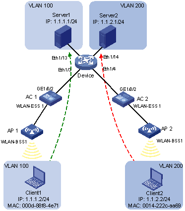
As shown in Figure 7:
· WLAN-ESS 1 of AC 1 and AC 2 are each connected to a meeting room. Client 1 and Client 2 are used for meeting and may be used in either of the two meeting rooms.
· Client 1 and Client 2 are owned by different departments. The two departments use VLAN 100 and VLAN 200 respectively. Each client can access only its own department server no matter which meeting room it is used in.
· The MAC address of Client 1 is 000D-88F8-4E71, and that of Client 2 is 0014-222C-AA69.
Configuration consideration
· Create VLANs 100 and 200.
· Configure the uplink ports of AC 1 and AC 2 as trunk ports, and assign them to VLANs 100 and 200.
· Configure the downlink ports of Device as trunk ports, and assign them to VLANs 100 and 200. Assign the uplink ports of Device to VLANs 100 and 200.
· Associate the MAC address of Client 1 with VLAN 100, and the MAC address of Client 2 with VLAN 200.
Configuration procedure
1. Configure AC 1:
# Create VLANs 100 and 200.
<AC1> system-view
[AC1] vlan 100
[AC1-vlan100] quit
[AC1] vlan 200
[AC1-vlan200] quit
# Associate the MAC address of Client 1 with VLAN 100, and the MAC address of Client 2 with VLAN 200.
[AC1] mac-vlan mac-address 000d-88f8-4e71 vlan 100
[AC1] mac-vlan mac-address 0014-222c-aa69 vlan 200
# Configure Client 1 and Client 2 to access the network through WLAN-ESS 1. Configure WLAN-ESS 1 as a hybrid port that sends packets of VLANs 100 and 200 untagged, and enable the MAC-based VLAN feature on it.
[AC1] interface wlan-ess 1
[AC1-WLAN-ESS1] port link-type hybrid
[AC1-WLAN-ESS1] port hybrid vlan 100 200 untagged
Please wait... Done.
[AC1-WLAN-ESS1] mac-vlan enable
[AC1-WLAN-ESS1] quit
# Create a service template, and set its SSID to vlan100.
[AC1]wlan service-template 2 clear
[AC1-wlan-st-2]ssid vlan100
[AC1-wlan-st-2]bind wlan-ess 1
[AC1-wlan-st-2]authentication-method open-system
[AC1-wlan-st-2]service-template enable
[AC1-wlan-st-2]quit
# Create an AP template named ap1.
[AC1]wlan ap ap1 model wa1208e-gnp
[AC1-wlan-ap-ap1]serial-id 210235A0C509B001138
[AC1-wlan-ap-ap1]radio 1
# Bind service template 2 to interface radio1 of AP 1.
[AC1-wlan-ap-ap1]service-template 2
[AC1-wlan-ap-ap1]radio enable
[AC1-wlan-ap-ap1]quit
# To enable the clients to access Server 1 and Server 2, configure the uplink port GigabitEthernet 1/0/2 as a trunk port, and assign it to VLANs 100 and 200.
[AC1] interface gigabitethernet 1/0/2
[AC1-GigabitEthernet1/0/2] port link-type trunk
[AC1-GigabitEthernet1/0/2] port trunk permit vlan 100 200
[AC1-GigabitEthernet1/0/2] quit
2. Configure Device:
# Create VLANs 100 and 200. Assign Ethernet 1/13 to VLAN 100, and Ethernet 1/14 to VLAN 200.
<Device> system-view
[Device] vlan 100
[Device-vlan100] port ethernet 1/13
[Device-vlan100] quit
[Device] vlan 200
[Device-vlan200] port ethernet 1/14
[Device-vlan200] quit
# Configure Ethernet 1/3 and Ethernet 1/4 as trunk ports, and assign them to VLANs 100 and 200.
[Device] interface ethernet 1/3
[Device-Ethernet1/3] port link-type trunk
[Device-Ethernet1/3] port trunk permit vlan 100 200
[Device-Ethernet1/3] quit
[Device] interface ethernet 1/4
[Device-Ethernet1/4] port link-type trunk
[Device-Ethernet1/4] port trunk permit vlan 100 200
[Device-Ethernet1/4] quit
3. Configure AC 2 in the same way AC 1 is configured.
Verifying the configuration
1. Client 1 can access Server 1 only, and Client 2 can access Server 2 only.
2. On AC 1 and AC 2, you can see that VLAN 100 is associated with the MAC address of Client 1, and VLAN 200 is associated with the MAC address of Client 2.
[AC1] display mac-vlan all
The following MAC VLAN addresses exist:
S:Static D:Dynamic
MAC ADDR MASK VLAN ID PRIO STATE
--------------------------------------------------------
000d-88f8-4e71 ffff-ffff-ffff 100 0 S
0014-222c-aa69 ffff-ffff-ffff 200 0 S
Total MAC VLAN address count:2
Configuration guidelines
· MAC-based VLAN can be configured only on hybrid ports.
· MAC-based VLAN is usually configured on the downlink ports of access layer devices, and cannot be configured together with the link aggregation function.
Displaying and maintaining VLAN
|
Task |
Command |
Remarks |
|
Display VLAN information. |
display vlan [ vlan-id1 [ to vlan-id2 ] | all | dynamic | reserved | static ] [ | { begin | exclude | include } regular-expression ] |
Available in any view. |
|
Display VLAN interface information. |
display interface [ vlan-interface ] [ brief [ down ] ] [ | { begin | exclude | include } regular-expression ] display interface vlan-interface vlan-interface-id [ brief ] [ | { begin | exclude | include } regular-expression ] |
Available in any view. |
|
Display hybrid ports or trunk ports on the device. |
display port { hybrid | trunk } [ | { begin | exclude | include } regular-expression ] |
Available in any view. |
|
Display MAC address-to-VLAN entries. |
display mac-vlan { all | dynamic | mac-address mac-address [ mask mac-mask ] | static | vlan vlan-id } [ | { begin | exclude | include } regular-expression ] |
Available in any view. |
|
Display all interfaces with MAC-based VLAN enabled. |
display mac-vlan interface [ | { begin | exclude | include } regular-expression ] |
Available in any view. |
|
Clear statistics on a port. |
reset counters interface vlan-interface [ vlan-interface-id ] |
Available in user view. |