- Table of Contents
-
- 03-Layer 2 Configuration Guide
- 00-Preface
- 01-Ethernet Interface Configuration
- 02-Loopback and Null Interface Configuration
- 03-VLAN Configuration
- 04-MAC Address Table Configuration
- 05-Ethernet Link Aggregation Configuration
- 06-Spanning Tree Configuration
- 07-Layer 2 Forwarding Configuration
- 08-PPPoE Configuration
- 09-FPGA Fast Forwarding Configuration
- 10-QinQ Termination Configuration
- Related Documents
-
| Title | Size | Download |
|---|---|---|
| 08-PPPoE Configuration | 165.18 KB |
Configuring a dialer interface
Displaying and maintaining PPPoE
PPPoE server configuration example
PPPoE client configuration example
Configuring PPPoE
Support for this feature depends on the device model. For more information, see About the H3C Access Controllers Configuration Guides.
Overview
Point-to-Point Protocol over Ethernet (PPPoE) extends PPP by transporting PPP packets encapsulated in Ethernet over point-to-point links.
PPPoE can provide access to the Internet for the hosts in an Ethernet through a remote access device and implement access control and accounting on a per-host basis.
PPPoE network structure
PPPoE uses the client/server model. The PPPoE client initiates a connection request to the PPPoE server. After session negotiation, the PPPoE server provides access control and authentication to the PPPoE client.
The following network structures are available for PPPoE:
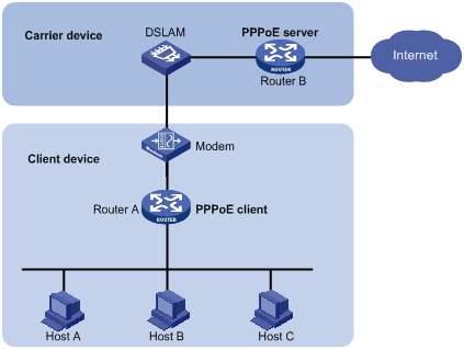
· As shown in Figure 1, a PPP session is established between Router A and Router B. All hosts share the PPP session and have no PPPoE client dialup software. Typically, enterprises use this network structure.
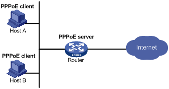
· As shown in Figure 2, a PPP session is established between each host (PPPoE client) and the carrier router (PPPoE server). The service provider assigns an account to each host for billing and control. The hosts must have PPPoE client dialup software. This network structure is applicable to campus and residential environments.
Protocols and standards
RFC 2516, A Method for Transmitting PPP Over Ethernet (PPPoE)
Configuring a PPPoE server
|
Step |
Command |
Remarks |
|
1. Enter system view. |
system-view |
N/A |
|
2. Create a virtual template (VT) interface. |
interface virtual-template number |
This operation also leads you to VT interface view. |
|
3. Enter interface view. |
interface interface-type interface-number |
You can configure the PPPoE server either on a Layer 3 Ethernet interface or on a VLAN interface. |
|
4. Enable PPPoE on the interface and bind this interface to a VT interface. |
pppoe-server bind virtual-template number |
Disabled by default. |
|
5. Return to system view. |
quit |
N/A |
|
6. Set the maximum number of PPPoE sessions allowed for a peer MAC address. |
pppoe-server max-sessions remote-mac number |
Optional. 100 by default. |
|
7. Set the maximum number of PPPoE sessions allowed for a local MAC address. |
pppoe-server max-sessions local-mac number |
Optional. 100 by default. |
|
8. Set the maximum number of PPPoE sessions allowed on the device. |
pppoe-server max-sessions total number |
Optional. The default setting is 4096. |
|
9. Set the upper threshold for the PPPoE abnormal offline event count. |
pppoe-server abnormal-offline-count threshold number |
Optional. 65535 by default. If the PPPoE abnormal offline event count in the last 5 minutes exceeds this threshold, the system outputs a trap message. |
|
10. Set the upper threshold for the PPPoE abnormal offline event percentage. |
pppoe-server abnormal-offline-percent threshold number |
Optional. 100 by default. If the PPPoE abnormal offline event percentage in the last 5 minutes exceeds this threshold, the system outputs a trap message. |
|
11. Set the lower threshold for the PPPoE normal offline event percentage. |
pppoe-server normal-offline-percent threshold number |
Optional. 0 by default. If the PPPoE normal offline event percentage in the last 5 minutes is lower than this threshold, the system outputs a trap message. |
|
12. Configure authentication and accounting on PPP users. |
See Security Configuration Guide. |
Optional. |
|
13. Disable PPP log displaying. |
pppoe-server log-information off |
Optional. Enabled by default. |
When you configure a static route on a VT interface, specify the next hop instead of the outgoing interface. If the outgoing interface is required, make sure the specified outgoing interface bound to the VT interface is effective.
Configuring a PPPoE client
PPPoE client configuration includes dialer interface configuration and PPPoE session configuration.
Configuring a dialer interface
Before establishing a PPPoE session, you must first create a dialer interface and configure a dialer bundle on the interface. Each PPPoE session uniquely corresponds to a dialer bundle, and each dialer bundle uniquely corresponds to a dialer interface. A PPPoE session uniquely corresponds to a dialer interface.
Configuring a dialer interface for an IPv4 PPPoE client
|
Step |
Command |
|
1. Enter system view. |
system-view |
|
1. Configure a dialer rule. |
dialer-rule dialer-group { protocol-name { deny | permit } | acl acl-number } |
|
2. Create a dialer interface and enter its view. |
interface dialer number |
|
3. Create a dialer user. |
dialer user username |
|
4. Assign an IP address to the interface. |
ip address { address mask | ppp-negotiate } |
|
5. Associate the interface with a dialer bundle. |
dialer bundle bundle-number |
|
6. Assign the interface to a dialer group. |
dialer-group group-number |
Configuring a dialer interface for an IPv6 PPPoE client
|
Step |
Command |
|
1. Enter system view. |
system-view |
|
2. Enable IPv6 forwarding. |
ipv6 |
|
3. Create a dialer interface and enter its view. |
interface dialer number |
|
4. Create a dialer user. |
dialer user username |
|
5. Specify an IPv6 address for the interface. |
See Layer 3—IP Services Configuration Guide. |
|
6. Associate the interface with a dialer bundle. |
dialer bundle bundle-number |
You can also configure PPP authentication or set other parameters on the dialer interface as needed.
For information about more IPv6-related commands, see Layer 3—IP Services Command Reference.
Configuring a PPPoE session
PPPoE sessions include the following types:
· Permanent PPPoE session—Established immediately when the line is physically up. It remains valid till a user terminates it explicitly.
· Packet-triggered PPPoE session—Established when there is a demand for data transmitting. It is terminated when idled for a specific period of time. That is, a packet-triggered PPPoE session may not be established even if the line is physically up.
· Diagnostic PPPoE session—Established immediately after the device configurations finish, and automatically terminates and then tries to re-establish at a pre-configured interval. By establishing and terminating PPPoE sessions periodically, you can monitor the operating status of the PPPoE links.
You can establish multiple PPPoE sessions on an Ethernet interface. In other words, an Ethernet interface can belong to multiple dialer bundles at the same time. However, a dialer bundle can only have one Ethernet interface. A PPPoE session uniquely corresponds to a dialer bundle, and vice versa.
IPv6 PPPoE sessions cannot be packet-triggered PPPoE sessions.
To configure a PPPoE session:
|
Step |
Command |
Remarks |
|
1. Enter system view. |
system-view |
N/A |
|
2. Enter Ethernet interface or VLAN interface view. |
interface interface-type interface-number |
N/A |
|
3. Create a PPPoE session, and specify a dialer bundle for the session. |
pppoe-client dial-bundle-number number [ no-hostuniq ] [ diagnose [ interval seconds ] | idle-timeout seconds [ queue-length packets ] ] |
By default, no PPPoE sessions are created. |
Displaying and maintaining PPPoE
|
Task |
Command |
Remarks |
|
Display the statistics and state information for a PPPoE server. |
display pppoe-server session all [ | { begin | exclude | include } regular-expression ] |
Available in any view. |
|
Display the statistics and state information for a PPPoE client. |
display pppoe-client session { packet | summary } [ dial-bundle-number number ] [ | { begin | exclude | include } regular-expression ] |
Available in any view. |
|
Clear PPP sessions on the PPPoE server. |
reset pppoe-server { all | interface interface-type interface-number | virtual-template number } |
Available in user view. |
|
Reset PPP sessions on the PPPoE client and reinitiate sessions. |
reset pppoe-client { all | dial-bundle-number number } |
Available in user view. |
PPPoE configuration examples
PPPoE server configuration example
Network requirements
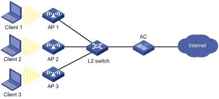
As shown in Figure 3, Clients 1, 2, and, 3 (PPPoE clients) belong to VLAN 1. They access the Internet through the AC. The AC connects to the Ethernet through VLAN-interface 1, and it connects to the Internet through VLAN-interface 2.
Configure PPPoE server and local authentication on the AC, so that the AC can perform local authentication and assign IP addresses to the users.
(Method 1) Configuring CHAP authentication
# Add a PPPoE user.
<AC> system-view
[AC] local-user user1
[AC-luser-user1] password simple pass1
[AC-luser-user1] service-type ppp
[AC-luser-user1] quit
# Configure virtual-template 1 on the AC.
[AC] interface virtual-template 1
[AC-Virtual-Template1] ppp authentication-mode chap domain system
[AC-Virtual-Template1] ppp chap user user1
[AC-Virtual-Template1] remote address pool 1
[AC-Virtual-Template1] ip address 1.1.1.1 255.0.0.0
[AC-Virtual-Template1] quit
# Configure PPPoE server on the AC.
[AC] interface Vlan-interface1
[AC- Vlan-interface1] pppoe-server bind virtual-template 1
[AC- Vlan-interface1] quit
# Configure local authentication for the users in the default ISP domain system.
[AC] domain system
[AC-isp-system] authentication ppp local
# Add a local IP address pool.
[AC-isp-system] ip pool 1 1.1.1.2 1.1.1.10
(Method 2) Configuring MS-CHAP authentication
# Add a PPPoE user.
<AC> system-view
[AC] local-user user1
[AC-luser-user1] password simple pass1
[AC-luser-user1] service-type ppp
[AC-luser-user1] quit
# Configure virtual-template 1 on the AC.
[AC] interface virtual-template 1
[AC-Virtual-Template1] ppp authentication-mode ms-chap domain system
[AC-Virtual-Template1] remote address pool 1
[AC-Virtual-Template1] ip address 1.1.1.1 255.0.0.0
[AC-Virtual-Template1] quit
# Configure the PPPoE server on the AC.
[AC] interface Vlan-interface1
[AC-Vlan-interface1] pppoe-server bind virtual-template 1
[AC-Vlan-interface1] quit
# Configure local authentication for the users in the default ISP domain system.
[AC] domain system
[AC-isp-system] authentication ppp local
# Add a local IP address pool.
[AC-isp-system] ip pool 1 1.1.1.2 1.1.1.10
Verifying the configuration
# Verify that the PPPoE clients can access the Internet by using the username user1 and password pass1 through the AC if they have PPPoE client software installed.
If you specify the authentication scheme as radius-scheme or hwtacacs-scheme by using the authentication ppp command, you also need to configure RADIUS/HWTACACS settings to enable AAA. For more information, see Security Configuration Guide.
PPPoE client configuration example
Network requirements
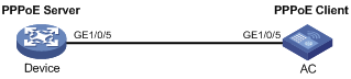
As shown in Figure 4, configure Device and the AC to make Device authenticate the AC using PAP or CHAP.
(Method 1) Configuring PAP authentication
1. Configure Device as the PPPoE server:
# Add a PPPoE user.
<Device> system-view
[Device] local-user user2
[Device-luser-user2] password simple hello
[Device-luser-user2] service-type ppp
[Device-luser-user2] quit
# Configure virtual template 1.
[Device] interface virtual-template 1
[Device-Virtual-Template1] ppp authentication-mode pap
[Device-Virtual-Template1] ip address 1.1.1.1 255.0.0.0
[Device-Virtual-Template1] remote address 1.1.1.2
[Device-Virtual-Template1] quit
# Configure the PPPoE server.
[Device] interface gigabitethernet 1/0/5
[Device-GigabitEthernet1/0/5] pppoe-server bind virtual-template 1
2. Configure the AC as the PPPoE client:
# Configure the dialer interface.
<AC> system-view
[AC] dialer-rule 1 ip permit
[AC] interface dialer 1
[AC-Dialer1] dialer user user2
[AC-Dialer1] dialer-group 1
[AC-Dialer1] dialer bundle 1
[AC-Dialer1] ip address ppp-negotiate
[AC-Dialer1] ppp pap local-user user2 password simple hello
[AC-Dialer1] quit
# Configure the PPPoE session.
[AC] interface gigabitethernet 1/0/5
[AC- GigabitEthernet1/0/5] pppoe-client dial-bundle-number 1
(Method 2) Configuring CHAP authentication
1. Configure Device as the PPPoE server:
# Add a PPPoE user.
<Device> system-view
[Device] local-user user2
[Device-luser-user2] password simple hello
[Device-luser-user2] service-type ppp
[Device-luser-user2] quit
# Configure virtual template 1.
[Device] interface virtual-template 1
[Device-Virtual-Template1] ppp authentication-mode chap
[Device-Virtual-Template1] ppp chap user user1
[Device-Virtual-Template1] ip address 1.1.1.1 255.0.0.0
[Device-Virtual-Template1] remote address 1.1.1.2
[Device-Virtual-Template1] quit
# Configure the PPPoE server.
[Device] interface gigabitethernet 1/0/5
[Device-GigabitEthernet1/0/5] pppoe-server bind virtual-template 1
2. Configure the AC as the PPPoE client:
# Configure the dialer interface.
<AC> system-view
[AC] dialer-rule 1 ip permit
[AC] interface dialer 1
[AC-Dialer1] dialer user user2
[AC-Dialer1] dialer-group 1
[AC-Dialer1] dialer bundle 1
[AC-Dialer1] ip address ppp-negotiate
[AC-Dialer1] ppp chap user user2
[AC-Dialer1] quit
[AC] local-user user1
[AC-luser-user1] password simple hello
[AC-luser-user1] quit
# Configure the PPPoE session.
[AC] interface gigabitethernet 1/0/5
[AC-GigabitEthernet1/0/5] pppoe-client dial-bundle-number 1