- Table of Contents
-
- H3C WX Series Access Controllers Web-Based Configuration Guide(R3308 R2308)-6W107
- 00-Preface
- 01-About the WX Series Access Controllers Web Configuration Guide
- 02-Quick Start
- 03-Web Overview
- 04-Summary
- 05-Device
- 06-Network
- 07-AP Configuration
- 08-Wireless Service
- 09-WLAN Roaming Configuration
- 10-Radio Configuration
- 11-Authentication
- 12-Security
- 13-QoS configuration
- 14-Advanced Settings
- 15-Stateful Failover Configuration
- Related Documents
-
| Title | Size | Download |
|---|---|---|
| 12-Security | 547.79 KB |
Contents
Configuring rogue device detection
Recommended configure procedure
Configuring detection rule lists
Enabling countermeasures and configuring aging time for detected rogue devices
Displaying statistics information
Configuring the blacklist and white list functions
Rogue detection configuration example
Before user isolation is enabled
After user isolation is enabled
Displaying user isolation information
User isolation configuration example
WLAN security overview
802.11 networks are susceptible to a wide array of threats such as unauthorized access points and clients, ad hoc networks, and Denial of Service (DoS) attacks. Rogue devices are a serious threat to enterprise security. To ensure security, the wireless intrusion detection system (WIDS) is introduced. WIDS provides early detection of malicious attacks and intrusions on a wireless network without affecting network performance, and provides real-time countermeasures.
WLAN security provides these features:
· Rogue detection
· WIDS attack detection
· Blacklist and white list.
Terminology
· Rogue AP—An unauthorized or malicious access point on the network, such as an employee setup AP, misconfigured AP, neighbor AP or an attacker operated AP. As it is not authorized, if there is any vulnerability in the AP, the hacker will have chance to compromise your network security.
· Rogue client—An unauthorized or malicious client on the network.
· Rogue wireless bridge—Unauthorized wireless bridge on the network.
· Monitor AP—An AP that scans or listens to 802.11 frames to detect rogue devices in the network.
· Ad hoc mode—A wireless client in ad-hoc mode can directly communicate with other stations without support from any other device.
Detecting rogue devices
Rogue detection is applicable to large wireless networks. It detects the presence of rogue devices in a WLAN network based on the pre-configured rules.
Rogue detection can detect different types of devices in a WLAN network, for example, rogue APs, rogue clients, rogue wireless bridges, and ad-hoc terminals. An AP can work in either of the following modes for rogue detection:
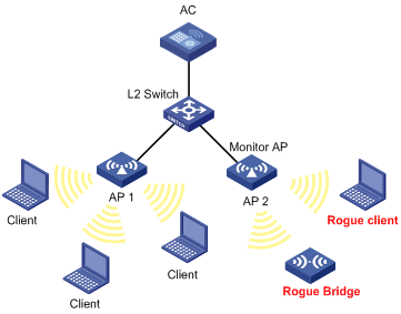
· Monitor mode: In this mode, an AP scans all 802.11g frames in the WLAN, but cannot provide WLAN services. As shown in Figure 1, AP 1 works as an access AP, and AP 2 works as a monitor AP to listen to all 802.11g frames. AP 2 cannot provide wireless access services.
Figure 1 Monitor AP for rogue detection
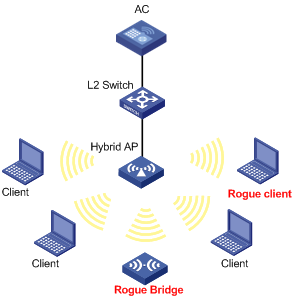
· Hybrid mode: In this mode, an AP can both scan devices in the WLAN and provide WLAN data services.
Figure 2 Hybrid AP for rogue detection
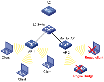
Taking countermeasures against rogue device attacks
You can enable the countermeasures on a monitor AP. The monitor AP downloads an attack list from the AC according to the countermeasure mode and takes countermeasures against detected rogue devices. The processing methods vary with rogue devices:
· If the rogue device is a rogue client, it will be logged out.
· If the rogue device is a rogue AP, legal clients will not use the rogue AP to access the WLAN.
· If the rogue device is an ad-hoc client, it is denied and ad-hoc clients cannot communicate with each other.
Figure 3 Taking countermeasures against rogue devices
Functionalities supported
The rogue detection feature supports the following functionalities:
· RF monitoring in different channels
· Rogue AP detection
· Rogue client detection
· Ad hoc network detection
· Wireless bridge detection
· Countermeasures against rogue devices, clients and ad hoc networks
WIDS attack detection
The WIDS attack detection function detects intrusions or attacks on a WLAN network, and informs the network administrator of the attacks through recording information or sending logs. WIDS detection supports detection of the following attacks:
· Flood attack
· Spoofing attack
· Weak IV attack
Flood attack detection
A flood attack refers to the case where WLAN devices receive large volumes of frames of the same kind within a short span of time. When this occurs, the WLAN devices get overwhelmed and are unable to service normal clients.
WIDS attacks detection counters flood attacks by constantly keeping track of the density of traffic generated by each device. When the traffic density of a device exceeds the limit, the device is considered flooding the network and, if the dynamic blacklist feature is enabled, will be added to the blacklist and forbidden to access the WLAN for a period of time.
WIDS inspects the following types of frames:
· Authentication requests and de-authentication requests
· Association requests, disassociation requests and reassociation requests
· Probe requests
· 802.11 null data frames
· 802.11 action frames.
Spoofing attack detection
In this kind of attack, a potential attacker can send frames in the air on behalf of another device. For instance, a client in a WLAN has been associated with an AP and works normally. In this case, a spoofed de-authentication frame can cause a client to get de-authenticated from the network and can affect the normal operation of the WLAN.
At present, spoofing attack detection counters this type of attack by detecting broadcast de-authentication and disassociation frames sent on behalf of an AP. When such a frame is received, it is identified as a spoofed frame, and the attack is immediately logged.
Weak IV detection
Wired Equivalent Privacy (WEP) uses an Initialization Vector (IV) to encrypt each frame. An IV and a key are used to generate a key stream, and thus encryptions using the same key have different results. When a WEP frame is sent, the IV used in encrypting the frame is also sent as part of the frame header.
However, if a WLAN device generates IVs in an insecure way, for example, if it uses a fixed IV for all frames, the shared secret key may be exposed to any potential attackers. When the shared secret key is compromised, the attacker can access network resources.
Weak IV detection counters this attack by verifying the IVs in WEP frames. Whenever a frame with a weak IV is detected, it is immediately logged.
Blacklist and white list
You can configure the blacklist and white list functions to filter frames from WLAN clients and thereby implement client access control.
WLAN client access control is accomplished through the following three types of lists.
· White list—Contains the MAC addresses of all clients allowed to access the WLAN. If the white list is used, only permitted clients can access the WLAN, and all frames from other clients will be discarded.
· Static blacklist—Contains the MAC addresses of clients forbidden to access the WLAN. This list is manually configured.
· Dynamic blacklist—Contains the MAC addresses of clients forbidden to access the WLAN. A client is dynamically added to the list if it is considered sending attacking frames until the timer of the entry expires. A dynamic blacklist can collaborate with ARP detection. When ARP detection detects any attacks, the MAC addresses of attackers are added to the dynamic blacklist. For more information about ARP detection, see "ARP attack defense configuration."
When an AP receives an 802.11 frame, it checks the source MAC address of the frame and processes the frame as follows:
1. If the source MAC address does not match any entry in the white list, the frame is dropped. If there is a match, the frame is considered valid and will be further processed.
2. If no white list entries exist, the static and dynamic blacklists are searched.
3. If the source MAC address matches an entry in any of the two lists, the frame is dropped.
4. If there is no match, or no blacklist entries exist, the frame is considered valid and will be further processed.
A static blacklist or white list configured on an AC applies to all APs connected to the AC, while a dynamic blacklist applies to APs that receive attack frames.
Figure 4 Network diagram for WLAN client access control
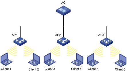
· In the topology above, three APs are connected to an AC. Configure white list and static blacklist entries on the AC, which will send all the entries to the APs. If the MAC address of a station, Client 1 for example, is present in the blacklist, it cannot access any of the APs. If only Client 1 is present in the white list, it can access any of the APs, and other clients cannot access any of the APs.
· Enable dynamic blacklist function on the AC. If AP 1 receives attack frames from Client 1, a dynamic blacklist entry is generated in the blacklist, and Client 1 cannot associate with AP 1, but can associate with AP 2 or AP 3. If AP 2 or AP 3 receives attack frames from Client 1, a new dynamic blacklist entry is generated in the blacklist.
Configuring rogue device detection
Recommended configure procedure
|
Step |
Remarks |
|
Required. By default, the AP operates in normal mode and only provides WLAN data services. |
|
|
Required. |
|
|
3. Enabling countermeasures and configuring aging time for detected rogue devices |
Optional. |
Configuring AP operating mode
1. Select Security > Rogue Detection from the navigation tree.
Figure 5 AP monitor configuration
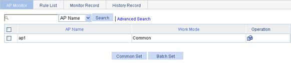
2.
On the AP Monitor tab, select the AP to be
configured and click the ![]() icon to enter the page shown in Figure 6.
icon to enter the page shown in Figure 6.
Figure 6 AP operating mode configuration
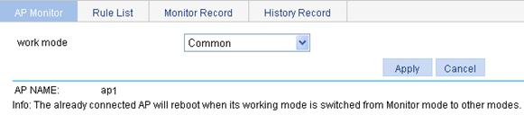
3. Configure the AP operating mode as described in Table 1.
4. Click Apply.
|
Item |
Description |
|
Work mode |
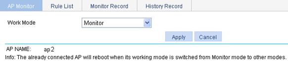
Configure the AP operating mode: · In normal mode, an AP provides WLAN data services but does not perform scanning. · In monitor mode, an AP scans all 802.11g frames in the WLAN, but cannot provide WLAN services. · In hybrid mode, an AP can both scan devices in the WLAN and provide WLAN data services.
· When an AP has its operating mode changed from normal to monitor, it does not restart. · When an AP has its operating mode changed from monitor to normal, it restarts. |
|
|
NOTE: · An AP operating in hybrid mode can provide WLAN data services as well as scanning devices in the WLAN, so WLAN service configurations are needed. · An AP operating in monitor mode cannot provide WLAN data services, so WLAN service configurations are not needed. |
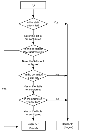
Configuring detection rules
· Check whether an AP is a rogue.
Figure 7 Checking whether an AP is a rogue
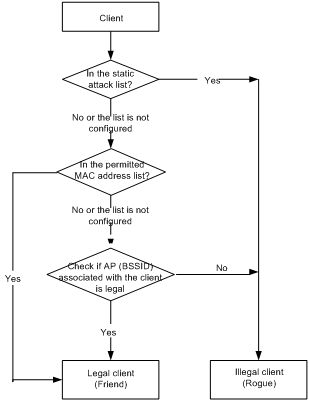
· Check whether a client is a rogue.
Figure 8 Checking whether a client is a rogue
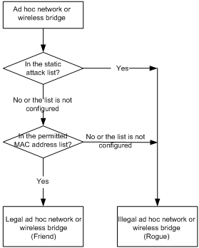
· Check whether an ad hoc network or a wireless bridge is a rogue.
Figure 9 Checking whether an ad hoc network or a wireless bridge is a rogue
Configuring detection rule lists
1. Select Security > Rogue Detection from the navigation tree.
2. Click the Rule List tab to enter detection rule list configuration page.
Figure 10 Rule list configuration
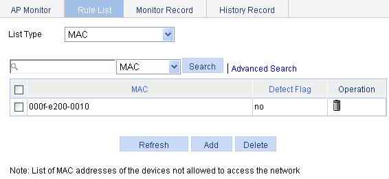
3. Configure the rule list as described in Table 2.
|
Item |
Description |
|
List Type |
· MAC—You can add MAC addresses to be permitted after selecting this option. · Wireless Service—You can add SSIDs to be permitted after selecting this option. · Vendor—You can specify vendors to be permitted after selecting this option. · Attacker—You can add the MAC address of a device to configure the device as a rogue. |
4. Select MAC from the list and click Add to enter the MAC address configuration page.
Figure 11 MAC address list configuration page
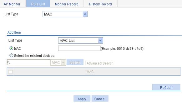
5. Configure the MAC address list as described in Table 3.
6. Click Apply.
|
Item |
Description |
|
MAC |
Enter the permitted MAC address in the box. |
|
Select the existent devices |
If you select this option, the MAC address table displays MAC addresses of the current devices. Select the MAC addresses to be permitted. |
The operation to add other types of lists is similar to the add operation of a MAC address list, and thus the description is omitted.
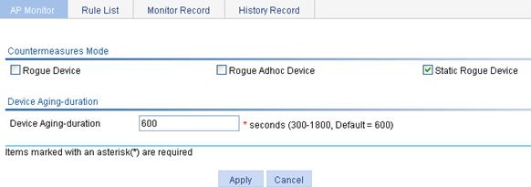
Enabling countermeasures and configuring aging time for detected rogue devices
1. Select Security > Rogue Detection from the navigation tree.
2. On the AP Monitor tab, click Common Set.
Figure 12 Common configuration
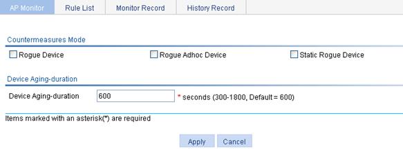
3. Perform common configuration as described in Table 4.
4. Click Apply.
|
Item |
Description |
|
Reverse Mode |
· Unlaw Set—Allows you to take countermeasures against rogue devices (including illegal APs and illegal clients). · Unlaw Adhoc Device—Allows you to take countermeasures against ad hoc devices. · Static Unlaw Device—Allows you to take countermeasures against rogue devices configured in the detection rule list. |
|
Device Aging-Duration |
Configure the aging time of entries in the device list. Once a rogue device is detected, an entry for it is added to the monitor record and the aging time starts. The aging time restarts if the device is detected again during the time. When the aging time is reached, the entry is deleted from the monitor record and added to the history record. |
Displaying monitor record
1. Select Security > Rogue Detection from the navigation tree.
2. Click the Monitor Record tab to enter the monitor record page.
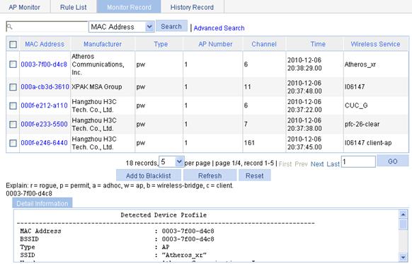
Table 5 Field description
|
Type |
Description |
|
Type |
· r—Rogue device. · p—Permitted device. · a—Ad hoc device. · w—AP. · b—Wireless bridge. · c—Client. For example, pw represents a permitted AP while rb represents a rogue wireless bridge. |
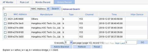
Displaying history record
1. Select Security > Rogue Detection from the navigation tree.
2. Click the History Record tab to enter the history record page.
Configuring WIDS
Configuring WIDS
1. Select Security > WIDS from the navigation tree.
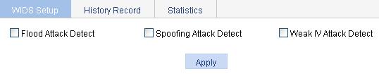
2. On the WIDS Setup tab, configure WIDS as described in Table 6.
3. Click Apply.
|
Item |
Description |
|
Flood Attack Detect |
If you select the option, flood attack detection is enabled. It is disabled by default. |
|
Spoofing Attack Detect |
If you select the option, spoofing attack detection is enabled. It is disabled by default. |
|
Weak IV Attack Detect |
If you select the option, Weak IV attack detection is enabled. It is disabled by default. |
Displaying history record
1. Select Security > WIDS from the navigation tree.
2. Click the History Record tab to enter the history information page.
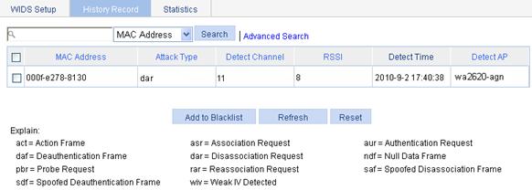
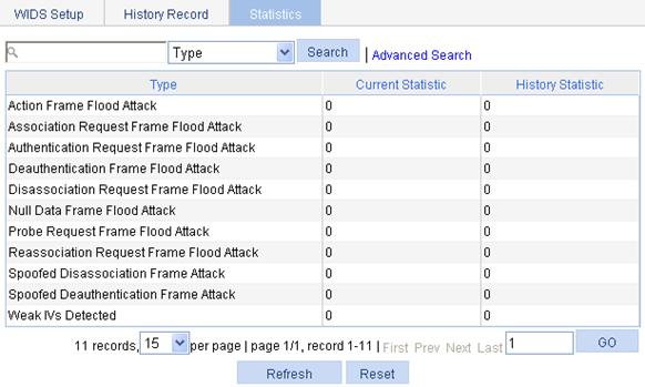
Displaying statistics information
1. Select Security > WIDS from the navigation tree.
2. Click the Statistics tab to enter the statistics information page.
Configuring the blacklist and white list functions
|
|
NOTE: A static blacklist or white list configured on an AC applies to all APs connected to the AC, while a dynamic blacklist applies to APs that receive attack frames. For more information, see "Blacklist and white list." |
Configuring dynamic blacklist
1. Select Security > Filter from the navigation tree.
Figure 18 Dynamic blacklist configuration page
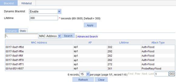
2. On the Blacklist tab, configure the dynamic blacklist as described in Table 7.
3. Click Apply.
|
Item |
Description |
|
Dynamic Blacklist |
· Enable—Enable dynamic blacklist. · Disable—Disable dynamic blacklist. |
|
Lifetime |
Configure the lifetime of the entries in the blacklist. When the lifetime of an entry expires, the entry is removed from the blacklist. |
|
|
NOTE: At present, these attacks can be detected through a dynamic blacklist: Assoc-Flood, Reassoc-Flood, Disassoc-Flood, ProbeReq-Flood, Action-Flood, Auth-Flood, Deauth-Flood and NullData-Flood. |
Configuring static blacklist
1. Select Security > Filter from the navigation tree.
2. On the Blacklist tab, click Static to enter the static blacklist configuration page.
Figure 19 Static blacklist configuration
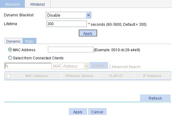
3. Click Add Static to enter the static blacklist configuration page.
Figure 20 Adding static blacklist
4. Add a static blacklist as described in Table 8.
5. Click Apply.
|
Item |
Description |
|
MAC Address |
Select MAC Address, and then add a MAC address to the static blacklist. |
|
Select from Connected Clients |
If you select the option, the table below lists the current existing clients. Select the options of the clients to add their MAC addresses to the static blacklist. |
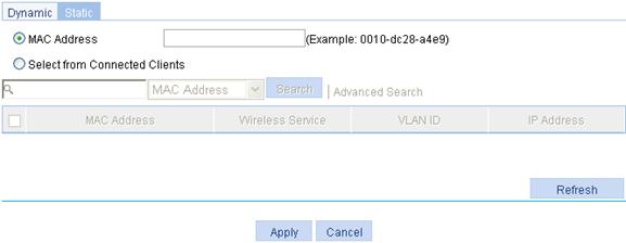
Configuring white list
1. Select Security > Filter from the navigation tree.
2. Click the Whitelist tab.
Figure 21 Whitelist configuration
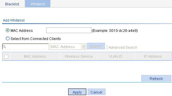
3. Click Add.
Figure 22 Adding a whitelist
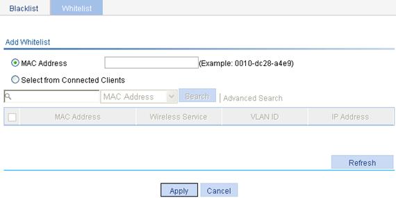
4. Add a white list as described in Figure 10.
5. Click Apply.
|
Item |
Description |
|
MAC Address |
Select MAC Address, and then add a MAC address to the white list. |
|
Select from Connected Clients |
If you select the option, the table below lists the current existing clients. Select the options of the clients to add their MAC addresses to the white list. |
Rogue detection configuration example
Network requirements
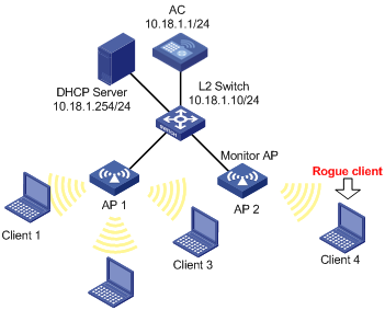
As shown in Figure 23, a monitor AP (AP 2 with serial ID SZ001) and AP 1 (serial ID SZ002) are connected to an AC through a Layer 2 switch.
· AP 1 operates in normal mode and provides WLAN data services only.
· AP 2 operates in monitor mode, and scans all 802.11g frames in the WLAN.
· Client 1 (MAC address 000f-e215-1515), Client 2 (MAC address 000f-e215-1530), and Client 3 (MAC address 000f-e213-1235) are connected to AP 1. They are configured as friends.
· Client 4 (MAC address 000f-e220-405e) is connected to AP 2. It is configured as a rogue device.
Configuration procedure
1. Configure AP 1 to operate in normal mode:
In normal mode, AP 1 provides WLAN data services only. For how to configure WLAN services, see "Access service configuration."
2. Configure AP 2 to operate in monitor mode:
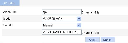
a. Select AP > AP Setup from the navigation tree.
b. Click Add.
c. On the page that appears, set the AP name to ap2., select the AP model WA2620-AGN, select Manual and enter the serial ID of AP 2.
d. Click Apply.
Figure 24 AP configuration
e. Select Security > Rogue Detection from the navigation tree.
f. Select Security > Rogue Detection from the navigation tree.
g. On the AP Monitor tab, click the ![]() icon corresponding to the target AP to
enter the operating mode configuration page.
icon corresponding to the target AP to
enter the operating mode configuration page.
h. Select the operating mode Monitor.
i. Click Apply.
Figure 25 AP operating mode configuration
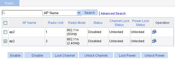
3. Enable the 802.11n(2.4GHz) radio mode:
a. Select Radio > Radio from the navigation tree to enter the AP radio configuration page.
b. Select the AP with the radio mode 802.11n(2.4GHz.
c. Click Enable.
Figure 26 Radio configuration
4. Configure rogue detection rules:
a. Select Security > Rogue Detection from the navigation tree.
b. Click the Rule List tab and click Add.
c. On the page that appears, enter 000f-e215-1515, 000f-e215-1530, and 000f-e213-1235 in the MAC Address field, and then click Apply.
d. Select Attacker, and click Add. Enter 000f-e220-405e in the MAC Address field and click Apply.
5. Enable countermeasures against the static rogue device:
a. Select Security > Rogue Detection from the navigation tree.
b. Click the AP Monitor tab, and click Common Set to enter the common configuration page.
c. Select Static Rogue Device. This is because the MAC address of Client 4 is added manually to the attacker list.
d. Click Apply.
Figure 27 Common configuration
Configuration guidelines
· The radio must be disabled so that the AP operation mode can be changed.
· If you configure more than one detection rule, you need to specify the rogue device types (AP, client, bridge, and ad hoc) and the rule matching order. For more information, see "User isolation."
· The wireless service configuration is needed for an AP operating in hybrid mode, and not needed for an AP in monitor mode.
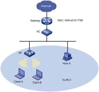
User isolation overview
Without user isolation, all the devices in the same VLAN can access each other directly, which brings forth security problems. User isolation can solve this problem. When an AC configured with user isolation receives unicast packets (broadcast packets and multicast packets in a VLAN are not isolated) from a wireless client to another wireless client or a wired PC in the same VLAN, or from a wired PC to a wireless client in the same VLAN, the AC determines whether to isolate the two devices according to the configured list of permitted MAC addresses.
To avoid user isolation from affecting communications between users and the gateway, you can add the MAC address of the gateway to the list of permitted MAC addresses.
User isolation both provides network services for users and isolates users, disabling them from communication at Layer-2 and thus ensuring service security.
Before user isolation is enabled
As shown in Figure 28, before user isolation is enabled in VLAN 2 on the AC, wireless terminals Client A and Client B and wired terminal Host A in the VLAN can communicate with each other and access the Internet.
Figure 28 User communication
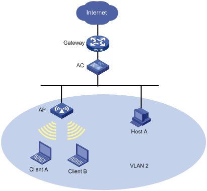
After user isolation is enabled
As shown in Figure 28, user isolation is enabled on the AC. Client A and Client B, and Host A in VLAN 2 access the Internet through the gateway.
· If you add the MAC address of the gateway to the permitted MAC address list, Client A, Client B, and Host A in the same VLAN are isolated, but they can access the Internet.
· If you add the MAC address of a user (Client A, for example) to the permitted MAC address list, Client A and Client B, and Client A and Host A can access each other directly, but Client B and Host A cannot.
To enable all the users in the VLAN to access one another and the Internet, you need to add the MAC address of the gateway and the MAC addresses of the users to the permitted MAC address list.
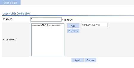
Configuring user isolation
Configuring user isolation
1. Select Security > User Isolation from the navigation tree.
2. Click Add .
The page for configuring user isolation appears.
Figure 29 Configuring user isolation
3. Configure user isolation as described in Table 10.
4. Click Apply.
|
Item |
Description |
|
VLAN ID |
Specify the VLAN in which user isolation is enabled. |
|
AccessMAC |
Specify the MAC addresses to be permitted by the AC. For more information, see "After user isolation is enabled." · Enter a MAC address in the field next to the Add button. · Click Add to add the MAC address to the permitted MAC list. · To delete a MAC address from the list, select an entry and click Delete.
· Broadcast or multicast MAC addresses cannot be specified as permitted MAC addresses. · Up to 16 permitted MAC addresses can be configured for one VLAN. |
To avoid network disruption caused by user isolation, add the MAC address of the gateway to the permitted MAC address list and then enable user isolation.
If you configure user isolation for a super VLAN, the configuration does not take effect on the sub-VLANs in the super VLAN, and you must configure user isolation on the sub-VLANs if needed.
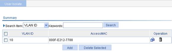
Displaying user isolation information
Select Security > User Isolation from the navigation tree to enter the page displaying user isolation configuration summary.
Figure 30 Displaying user isolation summary
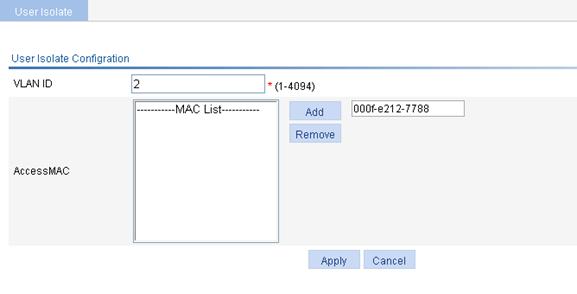
User isolation configuration example
Network requirements
As shown in Figure 31, isolate Client A, Client B, and Host A in VLAN 2 from one another while allowing them to access the Internet. The MAC address of the gateway is 000f-e212-7788.
Configuration procedure
1. Configure wireless service:
For how to configure wireless service, see "Access service configuration. "
2. Configure user isolation:
a. Select Security > User Isolation from the navigation tree.
b. Click Add to enter the page for configuring user isolation.
c. On the page that appears, enter the VLAN ID 2, add MAC address 000f-e212-7788 to the permitted MAC address list, and click Apply.
Figure 32 Configuring user isolation
Overview
The authorized IP function is to associate the HTTP or Telnet service with an ACL to filter the requests of clients. Only clients that pass the ACL filtering can access the device.
Configuring authorized IP
Before you configure authorized IP, you must create and configure the ACL. For ACL configuration, see "QoS configuration."
1. Select Security > Authorized IP from the navigation tree.
2. Click the Setup tab to enter the authorized IP configuration page.
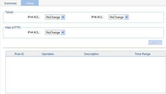
3. Configure an authorized IP as described in Table 11.
4. Click Apply.
|
Item |
Description |
|
|
Telnet |
IPv4 ACL |
Select the IPv4 to be associated with the Telnet service. Available IPv4 ACLs are those configured on the page you enter by selecting QoS > ACL IPv4. |
|
IPv6 ACL |
Select the IPv6 to be associated with the Telnet service. Available IPv6 ACLs are those configured on the page you enter by selecting QoS > ACL IPv6. |
|
|
Web (HTTP) |
IPv4 ACL |
Select the IPv4 ACL to be associated with the HTTP service. Available IPv4 ACLs are those configured on the page you enter by selecting QoS > ACL IPv4. |