- Table of Contents
-
- H3C WX Series Access Controllers Web-Based Configuration Guide(R3308 R2308)-6W107
- 00-Preface
- 01-About the WX Series Access Controllers Web Configuration Guide
- 02-Quick Start
- 03-Web Overview
- 04-Summary
- 05-Device
- 06-Network
- 07-AP Configuration
- 08-Wireless Service
- 09-WLAN Roaming Configuration
- 10-Radio Configuration
- 11-Authentication
- 12-Security
- 13-QoS configuration
- 14-Advanced Settings
- 15-Stateful Failover Configuration
- Related Documents
-
| Title | Size | Download |
|---|---|---|
| 09-WLAN Roaming Configuration | 331.13 KB |
Contents
WLAN roaming configuration examples
Intra-AC roaming configuration example
Inter-AC roaming configuration example
The Inter AC Tunneling Protocol (IACTP) is a proprietary protocol of H3C which defines how access controllers (ACs) communicate with each other. IACTP provides a generic packet encapsulation and transport mechanism between ACs to provide secure AC-AC communications based on the standard TCP client/server model.
A mobility group is a group of ACs that communicate with each other using the IACTP protocol. A maximum of 8 ACs can be present in a mobility group in current version. Formation and maintenance of a mobility group is done using IACTP.
IACTP provides a control tunnel for applications such as roaming to share/exchange messages. It also provides a data tunnel to encapsulate data packets to be transported between ACs. It can be used either with IPv4 or with IPv6.
Whenever a station supporting key caching associates to any of the ACs in a mobility group (which would be its Home-AC (HA)) for the first time, it goes through 802.1X authentication followed by 11 Key exchange. The station information is synchronized across the ACs in the mobility group prior to the roaming of the station within an AC/across ACs. When this station roams to another AC in the mobility group (which would be its Foreign-AC (FA)), the station information is used to fast authenticate the station by skipping 802.1X authentication, and performing only 802.11 key exchange to facilitate seamless roaming within the mobility group.
Configuring WLAN roaming
Configuring a roaming group
|
|
NOTE: Roaming group configuration is available only for inter-AC roaming. For the configuration example of inter-AC roaming, see "Inter-AC roaming configuration example." |
1. Select Roam > Roam Group from the navigation tree.
Figure 1 Configuring a roaming group
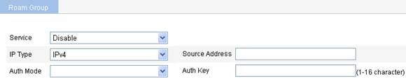
2. Configure a roaming group as described in Table 1.
3. Click Apply.
|
Item |
Description |
|
Service status |
· enable—Enable IACTP service. · disable—Disable IACTP service. |
|
IP type |
Select IPv4 or IPv6. |
|
Source address |
Source address of the IACTP protocol. |
|
Auth mode |
MD5—Select the MD5 authentication mode. This item is optional. The control message integrity can be verified when the MD5 authentication mode is selected. The sender (an AC) calculates a digest based on the content of a control message. On receiving such a message, the receiver (another AC in the roaming group) will calculate the digest again and compare it against the digest present in the message to verify the integrity of the packet received. If the digests are the same, the packet is not tampered. |
|
Auth key |
MD5 authentication key. If you select the MD5 authentication mode, you need to input an authentication key. |
Adding a group member
1. Select Roam > Roam Group from the navigation tree.
Figure 2 Adding a group member

2. Add a group member as described in Table 2.
3. Click Add.
4. Click Apply.
|
Item |
Description |
|
IP address |
Add the IP address of an AC to a roaming group.
When you configure a roaming group, the roaming group name configured for the ACs in the same roaming group must be the same. |
|
VLAN |
Configure the VLAN to which the roaming group member belongs. This configuration item is optional. |
|
|
NOTE: · The user profile configurations of the ACs in a roaming group must be the same. For more information, see "User configuration." · The ACs in a roaming group cannot be configured as hot backup ACs. |
Displaying client information
1. Select Roam > Roam Client from the navigation tree.
Figure 3 Displaying client information
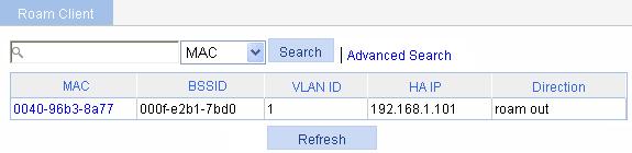
By clicking a target client, you can view the detailed information and roaming information of the client. The detailed information and roaming information of a client you can view by selecting Roam > Client Information are the same as those you can view by selecting Summary > Client. For the related information, see "Summary."
WLAN roaming configuration examples
Intra-AC roaming configuration example
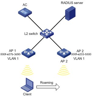
Network requirements
As shown in Figure 4, an AC has two APs associated and all of them are in VLAN 1. A client is associated with AP 1. Configure intra-AC roaming so that the client can associate with AP 2 when roaming to AP 2.
Configuring the AC
|
|
NOTE: If remote authentication is required in the authentication mode you select, configure the RADIUS server. For how to configure the RADIUS server, see "AAA configuration." |
1. Create two APs:
a. Select AP > AP Setup from the navigation tree.
b. Click Add.
c. On the page that appears, set the AP name to ap1, select the AP model WA2620-AGN, select manual from the Serial ID list, enter the serial ID of the AP, and click Apply.
d. Follow the same steps to create the other AP.
2. Configure wireless service:
a. Select Wireless Service > Access Service from the navigation tree.
b. Click Add.
c. On the page that appears, set the service name to Roam. And click Apply.
|
|
NOTE: For how to configure the authentication mode, see "Access service configuration." However, fast roaming can be implemented only when the RSN+802.1X authentication mode is adopted. |
3. Enable wireless service:
a. Select Wireless Service > Access Service from the navigation tree.
b. Select the Roam box.
c. Click Enable.
4. Bind AP radios to the wireless service:
a. Select Wireless Service > Access Service from the navigation tree.
b. Click the ![]() icon corresponding to the wireless service Roam to enter
the page for binding AP radio.
icon corresponding to the wireless service Roam to enter
the page for binding AP radio.
c. Select the box before ap1 with radio type 802.11n(2.4GHz), and the box before ap2 with radio type 802.11n(2.4GHz).
d. Click Bind.

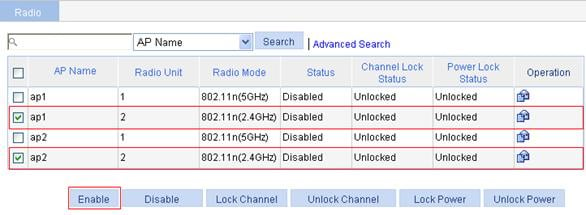
5. Enable dot11g radio:
a. Select Radio > Radio Setup from the navigation tree.
b. On the page that appears, select the box before ap1 with the radio mode 802.11n(2.4GHz), and select the box before ap2 with the radio mode 802.11n(2.4GHz).
c. Click Enable.
Verifying the configuration
1. Display the roaming information of the client:
a. Select Summary > Client from the navigation tree.
b. Select the Roam Information tab.
c. Click the desired client to view the roaming information of the client.
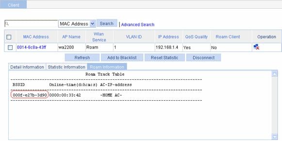
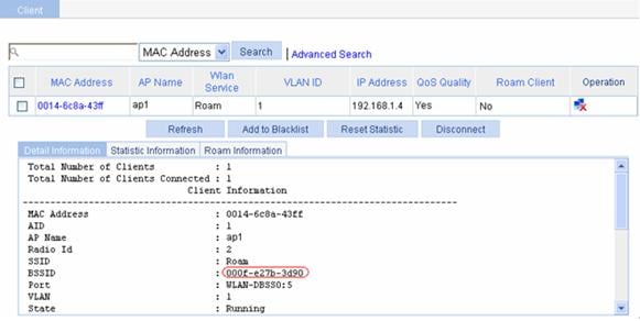
From the roaming information, you can see that the client accesses the WLAN through AP 1, and the BSSID of AP 1 is 000f-e27b-3d90 (see Figure 7.).
Figure 7 Client status before intra-AC roaming
d. Click Refresh.
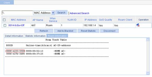
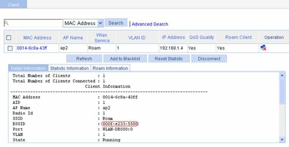
On the page that appears, you can see that the client is connected to the WLAN through AP 2, and the BSSID of AP 2 is 000f-e233-5500.
Figure 8 Client status after intra-AC roaming
2. View the Roam Status field:
a. Select Summary > Client from the navigation tree.
b. Click the Detail Information tab.
c. Click the desired client.
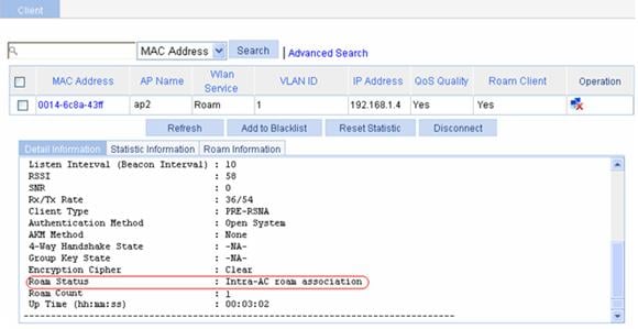
You can see that Intra-AC roam association is displayed in the Roam Status field.
Figure 9 Verifying intra-AC roaming
Configuration guidelines
When you configure intra-AC roaming, the SSIDs of the two APs must be the same. The same wireless service must be bound to the radios of the two APs in Bind AP radios to the wireless service.
Inter-AC roaming configuration example
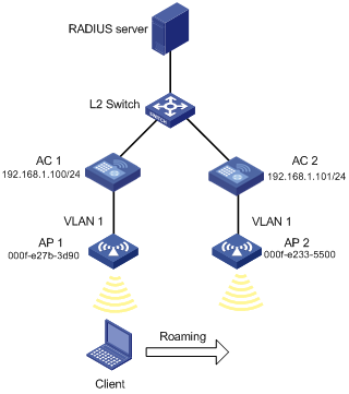
Network requirements
As shown in Figure 10, two ACs that each are connected to an AP are connected through a Layer 2 switch. Both ACs are in the same network. The IP address of AC 1 is 192.168.1.100 and that of AC 2 is 192.168.1.101. A client associates with AP 1.
Configure inter-AC roaming so that the client can associate with AP 2 when roaming to it.
Configuring AC 1 and AC 2
|
|
NOTE: If remote authentication is required in the authentication mode you select, configure the RADIUS server. For how to configure the RADIUS server, see "AAA configuration." |
1. Establish AC-AP connections:
Configure AC 1 and AC 2 so that a connection can be established between AP 1 and AC 1, and between AP 2 and AC 2. Only after the connections are established can you see that the two APs are in the running status. To view the AP status, select Summary > AP or AP > AP Setup.
For the related configuration, see "Access service configuration."
|
|
NOTE: For the configuration of authentication mode, see "Access service configuration." Fast roaming supporting key caching can be implemented only when RSN+802.1X authentication is adopted. |
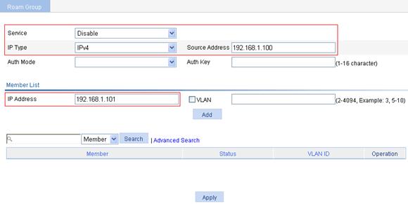
2. Configure a roaming group:
a. Select Roam > Roam Group from the navigation tree.
b. On the page that appears, select enable from the Service status list, select IPv4 from the IP Type list, enter 192.168.1.100 for Source address, the IP address of AC 1, enter the IP address of AC 2 in the member list, and click Add.
c. Click Apply.
Figure 11 Configuring a roaming group on AC 1
d. Create a roaming group on AC 2. The source address is the IP address of AC 2, and the member address is the IP address of AC 1. (Details not shown.)
Verifying the configuration
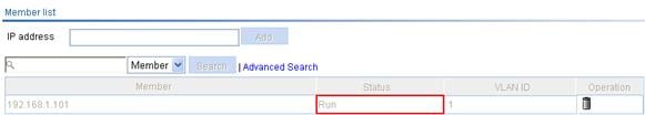
1. Verify the status of the roaming group:
a. On AC 1, select Roam > Roam Group from the navigation tree, and you can see that the group member 192.168.1.101 is in Run state.
Figure 12 Verifying the roaming group state
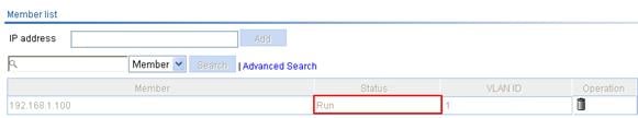
b. On AC 2, select Roam > Roam Group from the navigation tree, and you can see that the group member 192.168.1.100 is in Run state.
Figure 13 Verifying the roaming group state:
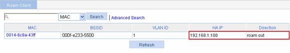
2. Display the client information:
a. After the client roams from AP 1 to AP 2, select Roam > Roam Client on AC 1.
You can see that the client roams out of 192.168.1.100.
Figure 14 Viewing client information
b. Select Roam > Roam Client on AC 2.
You can see that the client roams in to 192.168.1.100.
3. View connection information about the client that is associated with the AP, and the Roam Status field in the client detailed information:
a. Before roaming, select Summary > Client from the navigation tree on AC 1.
You can see that the client is associated with AP 1.
b. After roaming: Select Summary > Client from the navigation tree on AC 1.
The client has roamed from AP 1 to AP 2, so no client information is displayed on the page.
c. Select Summary > Client from the navigation tree on AC 2.
You can view the client information.
d. Select the Detail Information tab, and then click the desired client.
You will see that Inter-AC roam association is displayed in the Roam Status field, which indicates that the client has roamed to AP 2.
Figure 15 Verifying inter-AC roaming

4. View the BSSID field
a. Before roaming, select Summary > Client from the navigation tree on AC 1, select the Detail Information tab, and click the desired client to view the roaming information of the client.
The roaming information in Figure 16 shows that the client connects to the WLAN through AP 1, and the BSSID of AP 1 is 000f-e27b-3d90.
Figure 16 Client status before inter-AC roaming
b. Select Summary > Client, from the navigation tree on AC 2, select the Detail Information tab, and click the desired client to view the roaming information of the client.
The roaming information in Figure 17 shows that the client connects to the WLAN through AP 2, and the BSSID of AP 2 is 000f-e233-5500.
Figure 17 Client status after intra-AC roaming
Configuration guidelines
Follow these guidelines when you configure inter-AC roaming:
· The SSIDs and the authentication and encryption modes of two APs should be the same.
· A roaming group must be configured on both of the two ACs.
· Do not configure the ACs in a roaming group as AC backup.