- Table of Contents
-
- H3C WX Series Access Controllers Web-Based Configuration Guide(R3308 R2308)-6W107
- 00-Preface
- 01-About the WX Series Access Controllers Web Configuration Guide
- 02-Quick Start
- 03-Web Overview
- 04-Summary
- 05-Device
- 06-Network
- 07-AP Configuration
- 08-Wireless Service
- 09-WLAN Roaming Configuration
- 10-Radio Configuration
- 11-Authentication
- 12-Security
- 13-QoS configuration
- 14-Advanced Settings
- 15-Stateful Failover Configuration
- Related Documents
-
| Title | Size | Download |
|---|---|---|
| 06-Network | 1.05 MB |
Contents
Configuring a MAC address entry
Setting the aging time of MAC address entries
MAC address configuration example
Recommended configuration procedure
Introduction to gratuitous ARP
Static ARP configuration example
ARP attack protection configuration·
Source MAC address based ARP attack detection
ARP packet source MAC address consistency check
Configuring other ARP attack protection functions
Recommended configuration procedure
Enabling IGMP snooping globally
Configuring IGMP snooping on a VLAN
Configuring IGMP snooping on a port
Displaying IGMP snooping multicast entry information
IGMP snooping configuration examples
IPv4 and IPv6 routing configuration·
Displaying the IPv4 active route table
Displaying the IPv6 active route table
IPv4 static route configuration example
IPv6 static route configuration example
Recommended configuration procedure (for DHCP server)
Creating a static address pool for the DHCP server
Creating a dynamic address pool for the DHCP server
Enabling the DHCP server on an interface
Displaying information about assigned IP addresses
Recommended configuration procedure (for DHCP relay agent)
Enabling DHCP and configuring advanced parameters for the DHCP relay agent
Enabling the DHCP relay agent on an interface
Configuring and displaying clients' IP-to-MAC bindings
Recommended configuration procedure (for DHCP snooping)
Configuring DHCP snooping functions on an interface
Displaying clients' IP-to-MAC bindings
DHCP server configuration example
DHCP relay agent configuration example
DHCP snooping configuration example
Dynamic domain name resolution
Recommended configuration procedure
Configuring static name resolution table
Configuring dynamic domain name resolution
Configuring static name resolution table
Configuring dynamic domain name resolution
Configuring service management
|
|
NOTE: · MAC address configurations related to interfaces apply only to Layer 2 Ethernet interfaces. · This chapter covers only the management of static and dynamic MAC address entries, not multicast MAC address entries. |
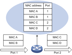
Overview
A device maintains a MAC address table for frame forwarding. Each entry in this table indicates the MAC address of a connected device, to which interface this device is connected and to which VLAN the interface belongs. A MAC address table consists of two types of entries: static and dynamic. Static entries are manually configured and never age out. Dynamic entries can be manually configured or dynamically learned and will age out.
When a frame arrives at a port, Port A for example, the device performs the following tasks:
1. Checks the frame for the source MAC address (MAC-SOURCE for example).
2. Looks up the MAC address in the MAC address table.
¡ If an entry is found, updates the entry.
¡ If no entry is found, adds an entry for the MAC address and the receiving port (Port A) to the MAC address table.
When receiving a frame destined for MAC-SOURCE, the device looks up the MAC address table and forwards it from port A.
|
|
NOTE: Dynamically learned MAC addresses cannot overwrite static MAC address entries, but the latter can overwrite the former. |
When forwarding a frame, the device adopts the following forwarding modes based on the MAC address table:
· Unicast mode—If an entry matching the destination MAC address exists, the device forwards the frame directly from the sending port recorded in the entry.
· Broadcast mode—If the device receives a frame with the destination address being all Fs, or no entry matches the destination MAC address, the device broadcasts the frame to all the ports except the receiving port.
Figure 1 MAC address table of the device
Configuring a MAC address entry
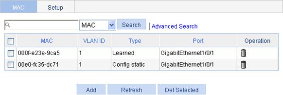
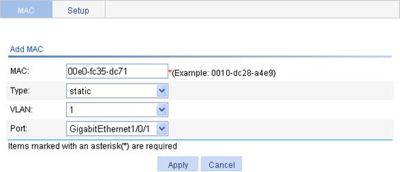
1. Select Network > MAC from the navigation tree. The system automatically displays the MAC tab, which shows all the MAC address entries on the device, as shown in Figure 2.
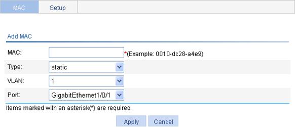
2. Click Add in the bottom to enter the page for creating MAC address entries, as shown in Figure 3.
Figure 3 Creating a MAC address entry
3. Configure the MAC address entry as described in Table 1.
4. Click Apply.
|
Item |
Description |
|
MAC |
Set the MAC address to be added. |
|
Type |
Set the type of the MAC address entry: · static—Static MAC address entries that never age out. · dynamic—Dynamic MAC address entries that will age out. · blackhole—Blackhole MAC address entries that never age out.
The tab displays the following types of MAC address entries: · Config static—Static MAC address entries manually configured by the users. · Config dynamic—Dynamic MAC address entries manually configured by the users. · Blackhole—Blackhole MAC address entries. · Learned—Dynamic MAC address entries learned by the device. · Other—Other types of MAC address entries. |
|
VLAN |
Set the ID of the VLAN to which the MAC address belongs. |
|
Port |
Set the port to which the MAC address belongs. |
Setting the aging time of MAC address entries
1. Select Network > MAC from the navigation tree.
2. Click the Setup tab to enter the page for setting the MAC address entry aging time, as shown in Figure 4.
Figure 4 Setting the aging time for MAC address entries
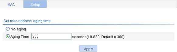
3. Set the aging time as described in Table 2.
4. Click Apply.
|
Item |
Description |
|
No-aging |
Specify that the MAC address entry never ages out. |
|
Aging time |
Set the aging time for the MAC address entry. |
MAC address configuration example
Network requirements
Use the MAC address table management function of the Web-based NMS. Create a static MAC address 00e0-fc35-dc71 for GigabitEthernet 1/0/1 in VLAN 1.
Configuration procedure
1. Create a static MAC address entry:
a. Select Network > MAC from the navigation tree to enter the MAC tab.
b. Click Add.
The page shown in Figure 5 appears.
c. Enter MAC address 00e0-fc35-dc71, select static from the Type list, select 1 from the VLAN list, and select GigabitEthernet1/0/1 from the Port list.
d. Click Apply.
Figure 5 Creating a static MAC address entry
VLAN configuration
Overview
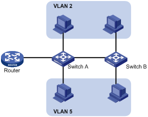
Ethernet is a network technology based on the Carrier Sense Multiple Access/Collision Detect (CSMA/CD) mechanism. As the medium is shared, collisions and excessive broadcasts are common on an Ethernet. To address the issue, virtual LAN (VLAN) was introduced to break a LAN down into separate VLANs. VLANs are isolated from each other at Layer 2. A VLAN is a bridging domain, and all broadcast traffic is contained within it, as shown in Figure 6.
You can implement VLANs based on a variety of criteria. The web interface, however, is available only for port-based VLANs, which group VLAN members by port. A port forwards traffic for a VLAN only after it is assigned to the VLAN.
For more information about VLAN, see H3C WX Series Access Controllers Layer 2 Configuration Guide.
Recommended configuration procedure
|
Step |
Remarks |
|
Required. |
|
|
Required. Select either task. Configure the untagged member ports and tagged member ports of the VLAN, or remove ports from the VLAN. |
|
Creating a VLAN
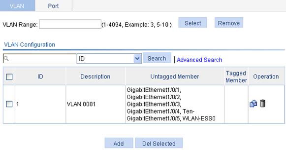
1. Select Network > VLAN from the navigation tree. The system automatically selects the VLAN tab and enters the page as shown in Figure 7.
Figure 7 VLAN configuration page
|
|
TIP: To easily configure a specific range of VLANs within a large number of VLANs, enter a VLAN range in the VLAN Range field and click Select, and all undesired VLANs will be filtered out. If you click Remove, all VLANs within this range will be deleted. |
2. Click Add to enter the page for creating a VLAN, as shown in Figure 8.
3. Enter the ID of the VLAN you want to create.
4. Click Apply.

Modifying a VLAN
1. Select Network > VLAN from the navigation tree. The system automatically selects the VLAN tab and enters the page as shown in Figure 7.
2.
Click the ![]() icon of the VLAN you want to modify to
enter the page as shown in Figure 9.
icon of the VLAN you want to modify to
enter the page as shown in Figure 9.
3. Configure the description and port members for the VLAN as described in Table 3.
4. Click Apply.
|
Item |
Description |
|
|
ID |
Display the ID of the VLAN to be modified. |
|
|
Description |
Set the description string of the VLAN. By default, the description string of a VLAN is its VLAN ID, such as VLAN 0001. |
|
|
Port |
Untagged Member |
Find the port to be modified and select the Untagged Member, Tagged Member, or Not a Member option for the port: · Untagged—Indicates that the port sends the traffic of the VLAN with the VLAN tag removed. · Tagged—Indicates that the port sends the traffic of the VLAN without removing the VLAN tag. · Not a Member—Removes the port from the VLAN.
When you configure an access port as a tagged member of a VLAN, the link type of the port is automatically changed into hybrid. |
|
Tagged Member |
||
|
Not a Member |
||
Modifying a port
1. Select Network > VLAN from the navigation tree
2. Click the Port tab to enter the page as shown in Figure 10.
Figure 10 Port configuration page
3.
Click the ![]() icon for the port to be modified to
enter the page as shown in Figure 11.
icon for the port to be modified to
enter the page as shown in Figure 11.
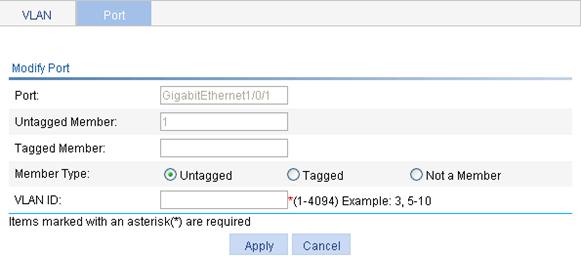
4. Configure the port as described in Table 4.
5. Click Apply.
|
Item |
Description |
|
|
Port |
Display the port to be modified. |
|
|
Untagged Member |
Display the VLAN(s) to which the port belongs as an untagged member. |
|
|
Tagged Member |
Display the VLAN(s) to which the port belongs as a tagged member. |
|
|
Member Type |
Untagged |
Select the Untagged, Tagged, or Not a Member option: · Untagged—Indicates that the port sends the traffic of the VLAN with the VLAN tag removed. · Tagged—Indicates that the port sends the traffic of the VLAN without removing the VLAN tag. · Not a Member—Removes the port from the VLAN.
· You cannot configure an access port as an untagged member of a nonexistent VLAN. · When you configure an access port as a tagged member of a VLAN, or configure a trunk port as an untagged member of multiple VLANs in bulk, the link type of the port is automatically changed into hybrid. · You can configure a hybrid port as a tagged or untagged member of a VLAN only if the VLAN is an existing, static VLAN. |
|
Tagged |
||
|
Not a Member |
||
|
VLAN ID |
Specify the VLAN to which the port belongs. |
|
VLAN configuration examples
Network requirements
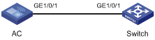
As shown in Figure 12:
· GigabitEthernet 1/0/1 of AC is connected to GigabitEthernet 1/0/1 of Switch.
· GigabitEthernet 1/0/1 on both devices are hybrid ports with VLAN 100 as their default VLAN.
· Configure GigabitEthernet 1/0/1 to permit packets of VLAN 2, VLAN 6 through VLAN 50, and VLAN 100 to pass through.
Configuring AC
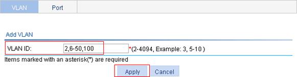
1. Create VLAN 2, VLAN 6 through VLAN 50, and VLAN 100:
a. Select Network > VLAN from the navigation tree to enter the VLAN tab.
b. Click Add.
c. Enter VLAN IDs 2,6-50,100, as shown in Figure 13.
d. Click Apply.
2. Configure GigabitEthernet 1/0/1 as an untagged member of VLAN 100:
a. Enter 100 in the VLAN Range field, as shown in Figure 14.
b. Click Select to display only the information of VLAN 100.
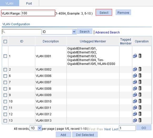
c.
Click the ![]() icon
of VLAN 100.
icon
of VLAN 100.
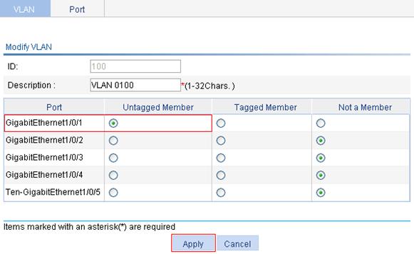
d. Select the Untagged Member option for port GigabitEthernet 1/0/1, as shown in Figure 15.
e. Click Apply.
3. Configure GigabitEthernet 1/0/1 as a tagged member of VLAN 2, and VLAN 6 through VLAN 50:
a. Select Network > VLAN from the navigation tree and then select the Port tab.
b. Click the ![]() icon of port GigabitEthernet 1/0/1.
icon of port GigabitEthernet 1/0/1.
c. Select the Tagged option, and enter VLAN IDs 2, 6-50, as shown in Figure 16.
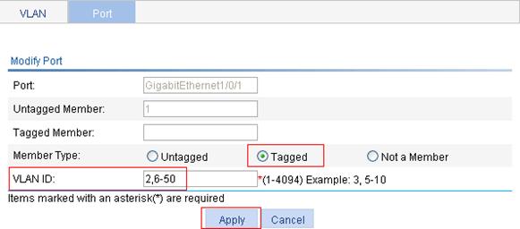
d. Click Apply. A dialog box appears asking you to confirm the operation.
e. Click OK in the dialog box.
Configuring Switch
The configuration on Switch is similar to that on AC.
Configuration guidelines
When you configure VLAN, follow these guidelines:
· VLAN 1 is the default VLAN, which cannot be manually created or removed.
· Some VLANs are reserved for special purposes. You cannot manually create or remove them.
· Dynamic VLANs cannot be manually removed.
Overview
Introduction to ARP
The Address Resolution Protocol (ARP) is used to resolve an IP address into an Ethernet MAC address (or physical address).
In an Ethernet LAN, a device uses ARP to resolve the IP address of the next hop to the corresponding MAC address.
For more information about ARP, see H3C WX Series Access Controllers Layer 3 Configuration Guide.
Introduction to gratuitous ARP
Gratuitous ARP packets
In a gratuitous ARP packet, the sender IP address and the target IP address are the IP address of the sending device, the sender MAC address is the MAC address of the sending device, and the target MAC address is the broadcast address ff:ff:ff:ff:ff:ff.
A device sends a gratuitous ARP packet for either of the following purposes:
· Determine whether its IP address is already used by another device. If the IP address is already used, the device will be informed of the conflict by an ARP reply.
· Inform other devices of the change of its MAC address.
Learning of gratuitous ARP packets
With this feature enabled, a device, upon receiving a gratuitous ARP packet, adds an ARP entry that contains the sender IP and MAC addresses in the packet to its ARP table. If the corresponding ARP entry exists, the device updates the ARP entry.
With this feature disabled, the device uses the received gratuitous ARP packets to update existing ARP entries, but not to create new ARP entries.
Displaying ARP entries
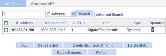
Select Network > ARP Management from the navigation tree to enter the default ARP Table page shown in Figure 17. All ARP entries are displayed on the page.
Figure 17 ARP Table configuration page
Creating a static ARP entry
1. Select Network > ARP Management from the navigation tree to enter the default ARP Table page shown in Figure 17.
2. Click Add to enter the New Static ARP Entry page, as shown in Figure 18.
Figure 18 Adding a static ARP entry
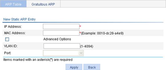
3. Configure the static ARP entry as described in Table 5.
4. Click Apply.
|
Item |
Description |
|
|
IP Address |
Enter an IP address for the static ARP entry. |
|
|
MAC Address |
Enter a MAC address for the static ARP entry. |
|
|
Advanced Options |
VLAN ID |
Enter a VLAN ID and specify a port for the static ARP entry.
The VLAN ID must be the ID of the VLAN that has already been created, and the port must belong to the VLAN. The corresponding VLAN interface must have been created. |
|
Port |
||
Removing ARP entries
1. Select Network > ARP Management from the navigation tree to enter the default ARP Table page shown in Figure 17.
2. Remove ARP entries:
¡ To remove specific ARP entries, select target ARP entries, and click Del Selected.
¡ To remove all static and dynamic ARP entries, click Delete Static and Dynamic.
¡ To remove all static ARP entries, click Delete Static.
¡ To remove all dynamic ARP entries, click Delete Dynamic.
Configuring gratuitous ARP
1. Select Network > ARP Management from the navigation tree.
2. Click the Gratuitous ARP tab to enter the page shown in Figure 19.
Figure 19 Gratuitous ARP configuration page
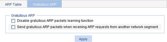
3. Configure gratuitous ARP as described in Table 6.
|
Item |
Description |
|
Disable gratuitous ARP packets learning function |
Disable learning of ARP entries according to gratuitous ARP packets. Enabled by default. |
|
Send gratuitous ARP packets when receiving ARP requests from another network segment |
Enable the device to send gratuitous ARP packets upon receiving ARP requests from another network segment. Disabled by default. |
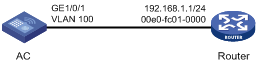
Static ARP configuration example
Network requirements
To enhance communication security between the AC and the router, configure a static ARP entry on the AC.
Configuration procedure
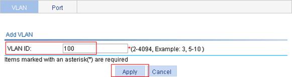
1. Create VLAN 100:
a. Select Network > VLAN from the navigation tree to enter the default VLAN page.
b. Click Add.
c. Enter 100 for VLAN ID, as shown in Figure 21.
d. Click Apply.
2. Add GigabitEthernet 1/0/1 to VLAN 100:
a. On the VLAN page, click the ![]() icon of VLAN 100.
icon of VLAN 100.
b. Select the Untagged Member option for GigabitEthernet1/0/1.
c. Click Apply.
Figure 22 Adding GigabitEthernet 1/0/1 to VLAN 100

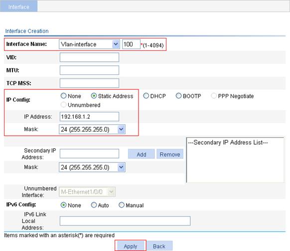
3. Configure VLAN-interface 100:
a. Select Device > Interface from the navigation tree.
b. Click Add.
c. On the page that appears, select Vlan-interface from the Interface Name list, and enter 100, select the Static Address option for IP Config, enter 192.168.1.2 for IP Address., and select 24 (255.255.255.0) for Mask.
d. Click Apply.
Figure 23 Configuring VLAN-interface 100
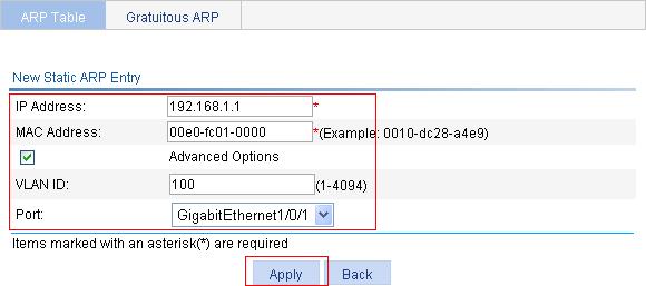
4. Create a static ARP entry:
a. Select Network > ARP Management from the navigation tree to enter the default ARP Table page.
b. Click Add.
c. On the page that appears, enter 192.168.1.1 for IP Address, enter 00e0-fc01-0000 for MAC Address, select the Advanced Options option, enter 100 for VLAN ID, and select GigabitEthernet1/0/1 from the Port list.
d. Click Apply.
Figure 24 Creating a static ARP entry
Although ARP is easy to implement, it provides no security mechanism and thus is prone to network attacks. Currently, ARP attacks and viruses are threatening LAN security. The device can provide multiple features to detect and prevent such attacks. This chapter mainly introduces these features.
ARP detection
The ARP detection feature enables access devices to block ARP packets from unauthorized clients to prevent user spoofing and gateway spoofing attacks.
ARP detection provides the following functions:
· User validity check—The device compares the sender IP and MAC addresses of a received ARP packet against the static IP source guard binding entries, DHCP snooping entries, 802.1X security entries, or OUI MAC addresses. If no match is found, the ARP packet is discarded.
· ARP packet validity check—The device does not check ARP packets received from an ARP trusted port. Upon receiving an ARP packet from an ARP untrusted port, the device checks the ARP packet based on source MAC address, destination MAC address, or source and destination IP addresses. ARP packets that fail the check are discarded.
For more information about ARP detection, see H3C WX Series Access Controllers Security Configuration Guide.
Source MAC address based ARP attack detection
This feature allows the device to check the source MAC address of ARP packets delivered to the CPU. If the number of ARP packets from a MAC address within five seconds exceeds the specified threshold, the device considers this an attack and adds the MAC address to the attack detection table. Before the attack detection entry is aged out, the device generates a log message upon receiving an ARP packet sourced from that MAC address and filters out subsequent ARP packets from that MAC address (in filter mode), or only generates a log message upon receiving an ARP packet sourced from that MAC address (in monitor mode).
A gateway or critical server may send a large number of ARP packets. To prevent these ARP packets from being discarded, you can specify the MAC address of the gateway or server as a protected MAC address. A protected MAC address is excluded from ARP attack detection even if it is an attacker.
ARP active acknowledgement
The ARP active acknowledgement feature is configured on gateway devices to identify invalid ARP packets.
ARP active acknowledgement works before the gateway creates or modifies an ARP entry to avoid generating any incorrect ARP entry.
ARP packet source MAC address consistency check
This feature enables a gateway device to filter out ARP packets with the source MAC address in the Ethernet header different from the sender MAC address in the ARP message, so that the gateway device can learn correct ARP entries.
Configuring ARP detection
|
|
NOTE: If both the ARP detection based on specified objects and the ARP detection based on static IP Source Guard binding entries/DHCP snooping entries/802.1X security entries/OUI MAC addresses are enabled, the former one applies first, and then the latter applies. |
1. Select Network > ARP Anti-Attack from the navigation tree to enter the default ARP Detection page shown in Figure 25.
Figure 25 ARP Detection configuration page
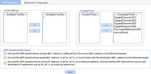
2. Configure ARP detection as described in Table 7.
3. Click Apply.
|
Item |
Description |
|
VLAN Settings |
Select VLANs on which ARP detection is to be enabled. To add VLANs to the Enabled VLANs list box, select one or multiple VLANs from the Disabled VLANs list box and click the << button. To remove VLANs from the Enabled VLANs list box, select one or multiple VLANs from the list box and click the >> button. |
|
Trusted Ports |
Select trusted ports and untrusted ports. To add ports to the Trusted Ports list box, select one or multiple ports from the Untrusted Ports list box and click the << button. To remove ports from the Trusted Ports list box, select one or multiple ports from the list box and click the >> button. |
|
ARP Packet Validity Check |
Select ARP packet validity check modes, including: · Discard the ARP packet whose sender MAC address is different from the source MAC address in the Ethernet header. · Discard the ARP packet whose target MAC address is all 0s, all 1s, or inconsistent with the destination MAC address in the Ethernet header. · Discard the ARP request whose source IP address is all 0s, all 1s, or a multicast address, and discard the ARP reply whose source and destination IP addresses are all 0s, all 1s, or multicast addresses. ARP packet validity check takes precedence over user validity check. If none of the above is selected, the system does not check the validity of ARP packets. |
Configuring other ARP attack protection functions
Other ARP attack protection functions include source MAC address based ARP attack detection, ARP active acknowledgement, and ARP packet source address consistency check.
1. Select Network > ARP Anti-Attack from the navigation tree.
2. Click the Advanced Configuration tab to enter the page shown in Figure 26.
Figure 26 Advanced Configuration page
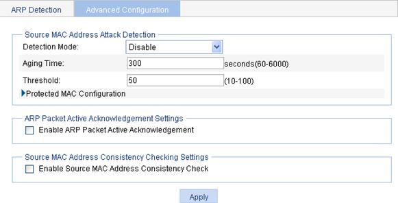
3. Configure ARP attack protection parameters as described in Table 8.
4. Click Apply.
|
Item |
Description |
|
|
Source MAC Address Attack Detection |
Detection Mode |
Select the detection mode for source MAC address based ARP attack detection. The detection mode can be: · Disable—The source MAC address attack detection is disabled. · Filter Mode—The device generates an alarm and filters out ARP packets sourced from a MAC address if the number of ARP packets received from the MAC address within five seconds exceeds the specified value. · The device only generates an alarm if the number of ARP packets sent from a MAC address within five seconds exceeds the specified value. |
|
Aging Time |
Enter the aging time of the source MAC address based ARP attack detection entries. |
|
|
Threshold |
Enter the threshold of source MAC address based ARP attack detection. |
|
|
Protected MAC Configuration |
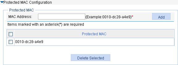
Add a protected MAC address in the following way: 1. Expand Protected MAC Configuration and contents are displayed as shown in Figure 27. 2. Enter a MAC address. 3. Click Add. A protected MAC address is excluded from ARP attack detection even if it is an attacker. You can specify certain MAC addresses, such as that of a gateway or an important server, as a protected MAC address. |
|
|
Enable ARP Packet Active Acknowledgement |
Enable or disable ARP packet active acknowledgement. |
|
|
Enable Source MAC Address Consistency Check |
Enable or disable source MAC address consistency check. |
|
Figure 27 Protected MAC configuration
IGMP snooping configuration
Overview
Internet Group Management Protocol (IGMP) snooping is a multicast constraining mechanism that runs on Layer 2 devices to manage and control multicast groups.
By analyzing received IGMP messages, a Layer 2 device that is running IGMP snooping establishes mappings between ports and multicast MAC addresses and forwards multicast data based on these mappings.
As shown in Figure 28, when IGMP snooping is not running on the switch, multicast packets are flooded to all devices at Layer 2. However, when IGMP snooping is running on the switch, multicast packets for known multicast groups are multicast to the receivers, rather than broadcast to all hosts, at Layer 2.
Figure 28 Multicast forwarding before and after IGMP snooping runs
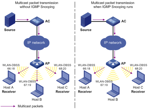
IGMP snooping sends Layer 2 multicast packets to the intended receivers only. This mechanism provides the following advantages:
· Reducing Layer 2 broadcast packets and saving network bandwidth
· Enhancing the security of multicast packets
· Facilitating the implementation of accounting for each host
For more information about IGMP snooping, see H3C WX Series Access Controllers IP Multicast Configuration Guide.
Recommended configuration procedure
|
Step |
Remarks |
|
Required. By default, IGMP snooping is disabled. |
|
|
Required. Enable IGMP snooping in the VLAN and configure the IGMP snooping version and querier feature. By default, IGMP snooping is disabled in a VLAN.
· IGMP snooping must be enabled globally before it can be enabled in a VLAN. · When you enable IGMP snooping in a VLAN, this function takes effect for ports in this VLAN only. |
|
|
Optional. Configure the maximum number of multicast groups allowed and the fast leave function for ports in the specified VLAN.
· Multicast routing or IGMP snooping must be enabled globally before IGMP snooping can be enabled on a port. · IGMP snooping configured on a port takes effect only after IGMP snooping is enabled in the VLAN or IGMP is enabled on the VLAN interface. |
|
|
Optional. |
Enabling IGMP snooping globally
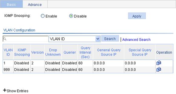
1. Select Network > IGMP snooping from the navigation tree to enter the basic configuration page shown in Figure 29.
2. Select Enable, and click Apply.
Figure 29 Basic IGMP snooping configurations
Configuring IGMP snooping on a VLAN
1. Select Network > IGMP snooping from the navigation tree to enter the basic configuration page shown in Figure 29.
2.
Click the ![]() icon corresponding to the VLAN to enter the page you can configure
IGMP snooping in the VLAN, as shown in Figure 30.
icon corresponding to the VLAN to enter the page you can configure
IGMP snooping in the VLAN, as shown in Figure 30.
Figure 30 Configuring IGMP snooping in the VLAN
3. Configure IGMP snooping as described in Table 9.
4. Click Apply.
|
Item |
Description |
|
VLAN ID |
This field displays the ID of the VLAN to be configured. |
|
IGMP snooping |
Enable or disable IGMP snooping in the VLAN. You can proceed with the subsequent configurations only if Enable is selected here. |
|
Version |
By configuring an IGMP snooping version, you actually configure the versions of IGMP messages that IGMP snooping can process. · IGMP snooping version 2 can process IGMPv1 and IGMPv2 messages, but not IGMPv3 messages, which will be flooded in the VLAN. · IGMP snooping version 3 can process IGMPv1, IGMPv2, and IGMPv3 messages. |
|
Drop Unknown |
Enable or disable the function of dropping unknown multicast packets. Unknown multicast data refers to multicast data for which no entries exist in the IGMP snooping forwarding table. · With the function of dropping unknown multicast data enabled, the device drops all the unknown multicast data received. · With the function of dropping unknown multicast data disabled, the device floods unknown multicast data in the VLAN to which the unknown multicast data belong. |
|
Querier |
Enable or disable the IGMP snooping querier function. On a network without Layer 3 multicast devices, no IGMP querier-related function can be implemented because a Layer 2 device does not support IGMP. To address this issue, you can enable IGMP snooping querier on a Layer 2 device so that the device can generate and maintain multicast forwarding entries at data link layer, thereby implementing IGMP querier-related functions. |
|
Query interval |
Configure the IGMP query interval. |
|
General Query Source IP |
Source IP address of IGMP general queries. |
|
Special Query Source IP |
Source IP address of IGMP group-specific queries. |
Configuring IGMP snooping on a port
1. Select Network > IGMP snooping from the navigation tree to enter the basic configuration page.
2. Click the Advanced tab to enter the page shown in Figure 31.
Figure 31 Advanced configuration

3. Configure IGMP snooping on a port as described in Table 10.
4. Click Apply.
|
Item |
Description |
|
Port |
Select the port on which advanced IGMP snooping features are to be configured. After a port is selected, advanced features configured on this port are displayed at the lower part of this page. |
|
VLAN ID |
Specify a VLAN in which you can configure the fast leave function for the port or the maximum number of multicast groups allowed on the port. |
|
Group Limit |
Configure the maximum number of multicast groups that the port can join. With this feature, you can regulate multicast traffic on the port.
· When the number of multicast groups a port has joined reaches the configured threshold, the system deletes all the forwarding entries persistent on that port from the IGMP snooping forwarding table, and the hosts on this port must join the multicast groups again. · Support for the maximum number of multicast groups that a port can join may vary depending on your device model. For more information, see "Feature matrixes." |
|
Fast Leave |
Enable or disable the fast leave function for the port. With the fast leave function enabled on a port, the device, when receiving an IGMP leave message on the port, immediately deletes that port from the outgoing port list of the corresponding forwarding table entry. Then, when receiving IGMP group-specific queries for that multicast group, the device will not forward them to that port. In VLANs where only one host is attached to each port, the fast leave function helps improve bandwidth and resource usage.
If fast leave is enabled for a port to which more than one host is attached, when one host leaves a multicast group, the other hosts listening to the same multicast group will fail to receive multicast data. |
Displaying IGMP snooping multicast entry information
1. Select Network > IGMP snooping from the navigation tree to enter the basic configuration page shown in Figure 29.
2. Click the plus sign (+) in front of Show Entries to display IGMP snooping multicast entries, as shown in Figure 32.
Figure 32 Displaying entry information
3. Clicking the ![]() icon corresponding
to an entry to display the detailed information of the entry, as shown in Figure 33.
icon corresponding
to an entry to display the detailed information of the entry, as shown in Figure 33.
Figure 33 Detailed information of an entry

|
Field |
Description |
|
VLAN ID |
ID of the VLAN to which the entry belongs. |
|
Source |
Multicast source address, where 0.0.0.0 indicates all multicast sources. |
|
Group |
Multicast group address. |
|
Router port |
All router ports. |
|
Member port |
All member ports. |
IGMP snooping configuration examples
Network requirements
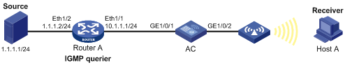
· As shown in Figure 34, Router A connects to a multicast source (Source) through Ethernet 1/2, and to AC through Ethernet 1/1.
· The multicast source sends multicast data to group 224.1.1.1. Host A is a receiver of the multicast group.
· IGMPv2 runs on Router A and IGMP snooping version 2 runs on AC.
· The function of dropping unknown multicast packets is enabled on AC to prevent AC from flooding multicast packets in the VLAN if no corresponding Layer 2 forwarding entry exists.
· The fast leave function is enabled for GigabitEthernet 1/0/2 on AC to improve bandwidth and resource usage.
Configuring IP addresses
Configure the IP address for each interface, as shown in Figure 34. (Details not shown.)
Configuring Router A
Enable IP multicast routing, enable PIM-DM on each interface, and enable IGMP on Ethernet 1/1. (Details not shown.)
Configuring the AC
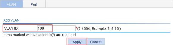
1. Create VLAN 100:
a. Select Network > VLAN from the navigation tree to enter the VLAN displaying page.
b. Click Add.
c. Enter the VLAN ID 100, as shown in Figure 35.
d. Click Apply.
Figure 35 Creating VLAN 100
2. Configure GigabitEthernet 1/0/1 and GigabitEthernet 1/0/2 as untagged members of VLAN 100:
a. Click the ![]() icon of VLAN 100 to
enter its configuration page.
icon of VLAN 100 to
enter its configuration page.
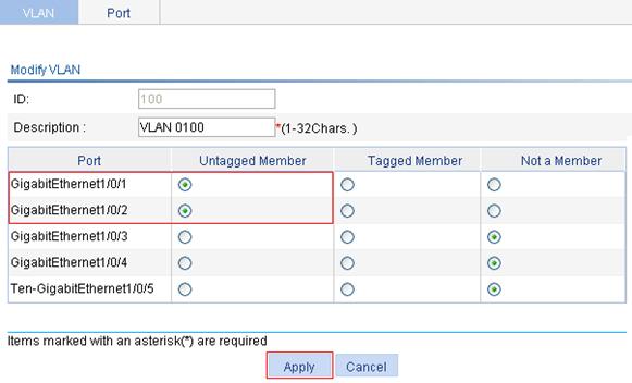
b. Select the Untagged Member option for GigabitEthernet 1/0/1 and GigabitEthernet 1/0/2, as shown in Figure 36.
c. Click Apply.
Figure 36 Adding a port to the VLAN
3. Enable IGMP snooping globally:
a. Select Network > IGMP snooping from the navigation tree to enter the basic configuration page.
b. Select the Enable option for IGMP Snooping.
c. Click Apply.
Figure 37 Enabling IGMP snooping globally

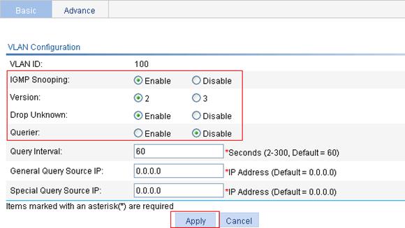
4. Enable IGMP snooping and the function of dropping unknown multicast data on VLAN 1:
a. Click the ![]() icon corresponding to VLAN 100.
icon corresponding to VLAN 100.
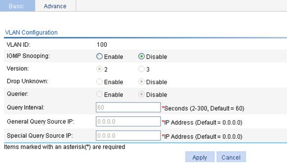
b. On the page that appears, select the Enable option for IGMP Snooping, select the 2 option for Version, and select the Enable option for Drop Unknown.
c. Click Apply.
Figure 38 Configuring the VLAN
5. Enable the fast leave function for GigabitEthernet 1/0/2:
a. Click the Advanced tab.
b. Select GigabitEthernet 1/0/2 from the Port list, enter the VLAN ID 100, and select the Enable option for Fast Leave.
c. Click Apply.
Figure 39 Advanced configuration

Verifying the configuration
Display the IGMP snooping multicast entry information on AC.
1. Select Network > IGMP snooping from the navigation tree to enter the basic configuration page.
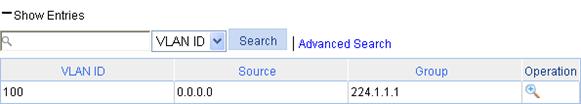
2. Click the plus sign (+) in front of Show Entries to view IGMP snooping multicast entries, as shown in Figure 40.
Figure 40 IGMP snooping multicast entry information displaying page

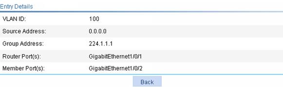
3. Click the ![]() icon corresponding to the multicast entry to view information about this entry, as shown in Figure 41. The
page shows that GigabitEthernet 1/0/2 of AC is added to multicast group
224.1.1.1.
icon corresponding to the multicast entry to view information about this entry, as shown in Figure 41. The
page shows that GigabitEthernet 1/0/2 of AC is added to multicast group
224.1.1.1.
Figure 41 Information about an IGMP snooping multicast entry
IPv4 and IPv6 routing configuration
|
|
NOTE: The term router in this document refers to routers, access controllers, unified switches, and access controller modules. |
Overview
Upon receiving a packet, a router determines the optimal route based on the destination address and forwards the packet to the next router in the path. When the packet reaches the last router, it then forwards the packet to the destination host. Routing provides the path information that guides the forwarding of packets.
A router selects optimal routes from the routing table, and sends them to the forwarding information base (FIB) table to guide packet forwarding. Each router maintains a routing table and a FIB table.
Static routes are manually configured. If a network's topology is simple, you only need to configure static routes for the network to work properly. Static routes cannot adapt to network topology changes. If a fault or a topological change occurs in the network, the network administrator must modify the static routes manually.
For more information about routing table and static routing, see H3C WX Series Access Controllers Layer 3 Configuration Guide.
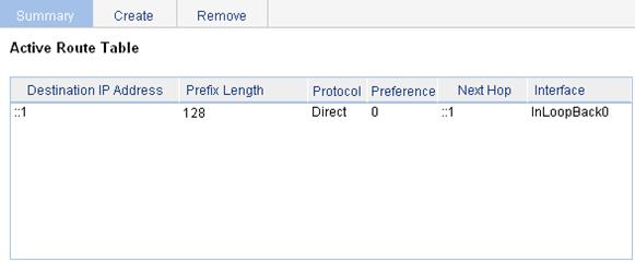
Displaying the IPv4 active route table
Select Network > IPv4 Routing from the navigation tree to enter the page shown in Figure 42.
Figure 42 IPv4 active route table
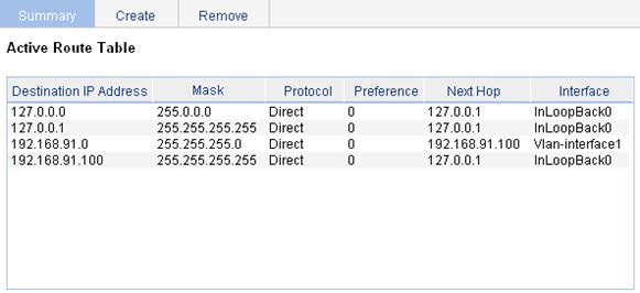
|
Field |
Description |
|
Destination IP Address |
Destination IP address and subnet mask of the IPv4 route. |
|
Mask |
|
|
Protocol |
Protocol that discovered the IPv4 route. |
|
Preference |
Preference value for the IPv4 route. The smaller the number, the higher the preference. |
|
Next Hop |
Next hop IP address of the IPv4 route. |
|
Interface |
Outgoing interface of the IPv4 route. Packets destined for the specified network segment will be sent out the interface. |
Creating an IPv4 static route
1. Select Network > IPv4 Routing from the navigation tree.
2. Click the Create tab to enter the IPv4 static route configuration page, as shown in Figure 43.
Figure 43 Creating an IPv4 static route
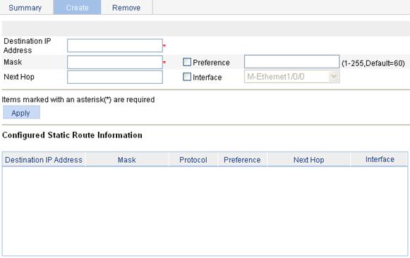
3. Specify relevant information as described in Table 13.
4. Click Apply.
|
Item |
Description |
|
Destination IP Address |
Enter the destination host or network IP address, in dotted decimal notation. |
|
Mask |
Enter the mask of the destination IP address. You can enter a mask length or a mask in dotted decimal notation. |
|
Preference |
Set a preference value for the static route. The smaller the number, the higher the preference. For example, specifying the same preference for multiple static routes to the same destination enables load sharing on the routes, while specifying different preferences enables route backup. |
|
Next Hop |
Enter the next hop IP address, in dotted decimal notation. |
|
Interface |
Select the outgoing interface. You can select any available Layer 3 interface, for example, a virtual interface, of the device. If you select NULL 0, the destination IP address is unreachable. |
Displaying the IPv6 active route table
Select Network > IPv6 Routing from the navigation tree to enter the page shown in Figure 44.
Figure 44 IPv6 active route table
|
Field |
Description |
|
Destination IP Address |
Destination IP address and prefix length of the IPv6 route. |
|
Prefix Length |
|
|
Protocol |
Protocol that discovered the IPv6 route. |
|
Preference |
Preference value for the IPv6 route. The smaller the number, the higher the preference. |
|
Next Hop |
Next hop IP address of the IPv6 route. |
|
Interface |
Outgoing interface of the IPv6 route. Packets destined for the specified network segment will be sent out the interface. |
Creating an IPv6 static route
1. Select Network > IPv6 Routing from the navigation tree.
2. Click the Create tab to enter the IPv6 static route configuration page, as shown in Figure 45.
Figure 45 Creating an IPv6 static route
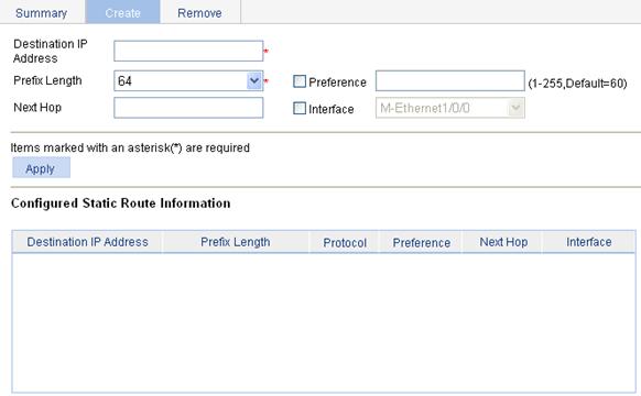
3. Specify relevant information as described in Table 15.
4. Click Apply.
|
Item |
Description |
|
Destination IP Address |
Enter the destination host or network IP address, in the X:X::X:X format. The 128-bit destination IPv6 address is a hexadecimal address with eight parts separated by colons (:). Each part is represented by a 4-digit hexadecimal integer. |
|
Prefix Length |
Enter the prefix length of the destination IPv6 address. |
|
Preference |
Set a preference value for the static route. The smaller the number, the higher the preference. For example, specifying the same preference for multiple static routes to the same destination enables load sharing on the routes, while specifying different priorities for them enables route backup. |
|
Next Hop |
Enter the next hop address, in the same format as the destination IP address. |
|
Interface |
Select the outgoing interface. You can select any available Layer 3 interface, for example, a virtual interface, of the device. If you select NULL 0, the destination IPv6 address is unreachable. |
IPv4 static route configuration example
Network requirements
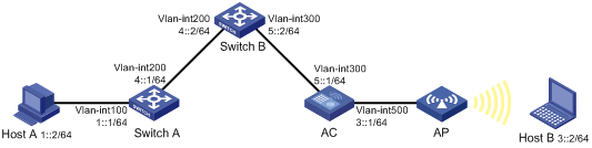
The IP addresses of devices are shown in Figure 46. IPv4 static routes must be configured on Switch A, Switch B and AC for Host A and Host B to communicate with each other.
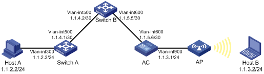
Configuration outlines
1. On Switch A, configure a default route with Switch B as the next hop.
2. On Switch B, configure one static route with Switch A as the next hop and the other with AC as the next hop.
3. On AC, configure a default route with Switch B as the next hop.
Configuration procedure
1. Configure a default route with the next hop address 1.1.4.2 on Switch A.
2. Configure two static routes on Switch B: one with destination address 1.1.2.0/24 and next hop address 1.1.4.1, and the other with destination address 1.1.3.0/24 and next hop address 1.1.5.6.
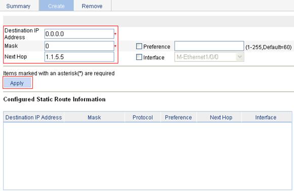
3. Configure a default route on AC:
a. Select Network > IPv4 Routing from the navigation tree.
b. Click the Create tab to enter the IPv4 static route configuration page, as shown in Figure 47.
c. Enter 0.0.0.0 for Destination IP Address, 0 for Mask, and 1.1.5.5 for Next Hop.
d. Click Apply.
Figure 47 Configuring a default route
Verifying the configuration
1. Display the route table:
Enter the IPv4 route page of Switch A, Switch B, and AC, respectively, to verify that the newly configured static routes are displayed as active routes on the page.
2. Ping Host B from Host A (assuming both hosts run Windows XP):
C:\Documents and Settings\Administrator>ping 1.1.3.2
Pinging 1.1.3.2 with 32 bytes of data:
Reply from 1.1.3.2: bytes=32 time=1ms TTL=128
Reply from 1.1.3.2: bytes=32 time=1ms TTL=128
Reply from 1.1.3.2: bytes=32 time=1ms TTL=128
Reply from 1.1.3.2: bytes=32 time=1ms TTL=128
Ping statistics for 1.1.3.2:
Packets: Sent = 4, Received = 4, Lost = 0 (0% loss),
Approximate round trip times in milli-seconds:
Minimum = 1ms, Maximum = 1ms, Average = 1ms
IPv6 static route configuration example
Network requirements
The IP addresses of devices are shown in Figure 48. IPv6 static routes must be configured on Switch A, Switch B and AC for Host A and Host B to communicate with each other.
Configuration outlines
1. On Switch A, configure a default route with Switch B as the next hop.
2. On Switch B, configure one static route with Switch A as the next hop and the other with AC as the next hop.
3. On AC, configure a default route with Switch B as the next hop.
Configuration procedure
1. Configure a default route with the next hop address 4::2 on Switch A.
2. Configure two static routes on Switch B: one with destination address 1::/64 and next hop address 4::1, and the other with destination address 3::/64 and next hop address 5::1.
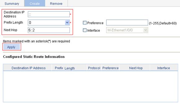
3. Configure a default route on AC:
a. Select Network > IPv6 Routing from the navigation tree.
b. Click the Create tab to enter the IPv6 static route configuration page, as shown in Figure 49.
c. Enter :: for Destination IP Address, select 0 for Prefix Length, and enter 5::2 for Next Hop.
d. Click Apply.
Figure 49 Configuring a default route
Verifying the configuration
1. Display the route table:
Enter the IPv6 route page of Switch A, Switch B, and AC, respectively, to verify that the newly configured static routes are displayed as active routes on the page.
2. Ping Host B from Switch A:
<SwitchA> system-view
[SwitchA] ping ipv6 3::2
PING 3::2 : 56 data bytes, press CTRL_C to break
Reply from 3::2
bytes=56 Sequence=1 hop limit=254 time = 63 ms
Reply from 3::2
bytes=56 Sequence=2 hop limit=254 time = 62 ms
Reply from 3::2
bytes=56 Sequence=3 hop limit=254 time = 62 ms
Reply from 3::2
bytes=56 Sequence=4 hop limit=254 time = 63 ms
Reply from 3::2
bytes=56 Sequence=5 hop limit=254 time = 63 ms
--- 3::2 ping statistics ---
5 packet(s) transmitted
5 packet(s) received
0.00% packet loss
round-trip min/avg/max = 62/62/63 ms
Configuration guidelines
When you configure a static route, follow these guidelines:
1. If you do not specify the preference when you configure a static route, the default preference is used. Reconfiguration of the default preference applies only to newly created static routes. Currently, the Web interface does not support configuration of the default preference.
2. When you configure a static route, the static route does not take effect if you specify the next hop address first and then configure it as the IP address of a local interface, such as an Ethernet interface and VLAN interface.
3. When specifying the output interface, note that:
¡ If NULL 0 or a loopback interface is specified as the output interface, there is no need to configure the next hop address.
¡ If a point-to-point interface is specified as the output interface, you do not need to specify the next hop or change the configuration after the peer address has changed. For example, a PPP interface obtains the peer's IP address through PPP negotiation, and therefore, you only need to specify it as the output interface.
¡ If the output interface is an NBMA or P2MP interface, which supports point-to-multipoint networks, the IP address-to-link layer address mapping must be established. Therefore, H3C recommends that you specify the next hop IP address when you configure it as the output interface.
¡ If you want to specify a broadcast interface (such as an Ethernet interface, virtual template, or VLAN interface) as the output interface, which may have multiple next hops, you must specify the next hop at the same time.
|
|
NOTE: · After the DHCP client is enabled on an interface, the interface can dynamically obtain an IP address and other configuration parameters from the DHCP server. This facilitates configuration and centralized management. For more information about the DHCP client configuration, see "Interface management." · For more information about DHCP, see H3C WX Series Access Controllers Layer 3 Configuration Guide. |
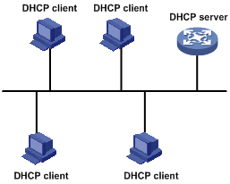
The Dynamic Host Configuration Protocol (DHCP) provides a framework to assign configuration information to network devices.
DHCP uses the client/server model. Figure 50 shows a typical a DHCP application.
Figure 50 A typical DHCP application
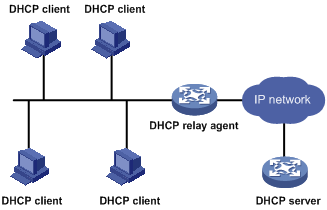
A DHCP client can obtain an IP address and other configuration parameters from a DHCP server on another subnet through a DHCP relay agent.
Figure 51 DHCP relay agent application
Introduction to DHCP snooping
|
|
NOTE: The DHCP snooping-enabled device must be either between the DHCP client and relay agent, or between the DHCP client and server. It does not work if it is between the DHCP relay agent and DHCP server. |
As a DHCP security feature, DHCP snooping can implement the following:
1. Recording IP-to-MAC mappings of DHCP clients
2. Ensuring DHCP clients to obtain IP addresses from authorized DHCP servers
Recording IP-to-MAC mappings of DHCP clients
DHCP snooping reads DHCP-REQUEST messages and DHCP-ACK messages from trusted ports to record DHCP snooping entries, including MAC addresses of clients, IP addresses obtained by the clients, ports that connect to DHCP clients, and VLANs to which the ports belong.
Ensuring DHCP clients to obtain IP addresses from authorized DHCP servers
If there is an unauthorized DHCP server on a network, DHCP clients may obtain invalid IP addresses and network configuration parameters, and cannot normally communicate with other network devices. With DHCP snooping, the ports of a device can be configured as trusted or untrusted, ensuring the clients to obtain IP addresses from authorized DHCP servers.
· Trusted—A trusted port forwards DHCP messages normally.
· Untrusted—An untrusted port discards the DHCP-ACK or DHCP-OFFER messages received from any DHCP server.
Recommended configuration procedure (for DHCP server)
|
Step |
Remarks |
|
Required. Enable DHCP globally. By default, global DHCP is disabled. |
|
|
2. Creating an address pool for the DHCP server |
Required. Use at least one approach.
· If the DHCP server and DHCP clients are on the same subnet, make sure the address pool is on the same network segment as the interface with the DHCP server enabled; otherwise, the clients will fail to obtain IP addresses. · If a DHCP client obtains an IP address via a DHCP relay agent, an IP address pool on the same network segment as the DHCP relay agent interface must be configured; otherwise, the client will fail to obtain an IP address. |
|
Optional. With the DHCP server enabled on an interface, upon receiving a client's request, the DHCP server will assign an IP address from its address pool to the DHCP client. With DHCP enabled, interfaces work in the DHCP server mode.
· An interface cannot serve as both the DHCP server and the DHCP relay agent. The latest configuration takes effect. · The DHCP server works on interfaces with IP addresses manually configured only. |
|
|
Optional. |
Enabling DHCP
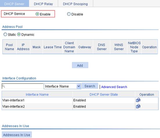
1. Select Network > DHCP from the navigation tree to enter the default DHCP Server page shown in Figure 52.
2. Select the Enable option on the upper part of the page to enable DHCP globally.
Figure 52 DHCP configuration page
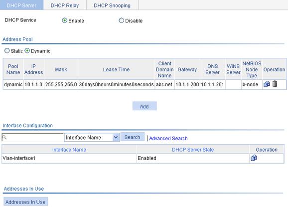
Creating a static address pool for the DHCP server
1. Select Network > DHCP from the navigation tree to enter the default DHCP Server page shown in Figure 52.
2. Select the Static option in the Address Pool field to view all static address pools.
3. Click Add to enter the page shown in Figure 53.
Figure 53 Creating a static address pool
4. Configure the static address pool as described in Table 16.
5. Click Apply.
|
Item |
Description |
|
IP Pool Name |
Enter the name of a static address pool. |
|
IP Address |
Enter an IP address and select a subnet mask for the static address pool. The IP address cannot be the IP address of any interface on the DHCP server. Otherwise, an IP address conflict may occur and the bound client cannot obtain an IP address correctly. You can enter a mask length or a mask in dotted decimal notation.. |
|
Mask |
|
|
Client MAC Address |
Configure the client MAC address or the client ID for the static address pool.
The client ID must be identical to the ID of the client to be bound. Otherwise, the client cannot obtain an IP address.. |
|
Client ID |
|
|
Client Domain Name |
Enter the domain name suffix for the client. With the suffix assigned, the client only needs to enter part of a domain name, and the system adds the domain name suffix for name resolution. |
|
Gateway Address |
Enter the gateway addresses for the client. A DHCP client that wants to access an external host needs to send requests to a gateway. You can specify gateways in each address pool and the DHCP server will assign gateway addresses while assigning an IP address to the client. Up to eight gateways can be specified in a DHCP address pool, separated by commas. |
|
DNS Server Address |
Enter the DNS server addresses for the client. To allow the client to access a host on the Internet through DNS, you need to specify a DNS server address. Up to eight DNS servers can be specified in a DHCP address pool, separated by commas. |
|
WINS Server Address |
Enter the WINS server addresses for the client. If b-node is specified for the client, you do not need to specify any WINS server address. Up to eight WINS servers can be specified in a DHCP address pool, separated by commas. |
|
NetBIOS Node Type |
Select the NetBIOS node type for the client. |
Creating a dynamic address pool for the DHCP server
1. Select Network > DHCP from the navigation tree to enter the default DHCP Server page shown in Figure 52.
2. Select the Dynamic option in the Address Pool field to view all dynamic address pools.
3. Click Add to enter the page shown in Figure 54.
Figure 54 Creating a dynamic address pool
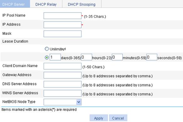
4. Configure the dynamic address pool as described in Table 17.
5. Click Apply.
|
Item |
Description |
|
|
IP Pool Name |
Enter the name of a dynamic address pool. |
|
|
IP Address |
Enter an IP address segment for dynamic allocation. To avoid address conflicts, the DHCP server excludes the IP addresses used by gateways or FTP servers from dynamic allocation. You can enter a mask length or a mask in dotted decimal notation. |
|
|
Mask |
||
|
Lease Duration |
Unlimited. |
Configure the address lease duration for the address pool. Unlimited indicates the infinite duration. |
|
days/hours/minutes/seconds. |
||
|
Client Domain Name |
Enter the domain name suffix for the client. With the suffix assigned, the client only needs to enter part of a domain name, and the system will add the domain name suffix for name resolution. |
|
|
Gateway Address |
Enter the gateway addresses for the client. DHCP clients that want to access hosts outside the local subnet request gateways to forward data. You can specify gateways in each address pool for clients and the DHCP server will assign gateway addresses while assigning an IP address to the client. Up to eight gateways can be specified in a DHCP address pool, separated by commas. |
|
|
DNS Server Address |
Enter the DNS server addresses for the client. To allow the client to access a host on the Internet via the host name, you need to specify DNS server addresses. Up to eight DNS servers can be specified in a DHCP address pool, separated by commas. |
|
|
WINS Server Address |
Enter the WINS server addresses for the client. If b-node is specified for the client, you do not need to specify any WINS server address. Up to eight WINS servers can be specified in a DHCP address pool, separated by commas. |
|
|
NetBIOS Node Type |
Select the NetBIOS node type for the client. |
|
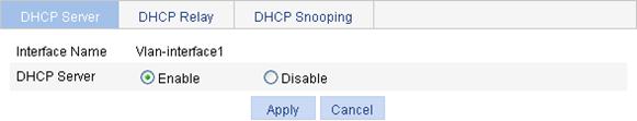
Enabling the DHCP server on an interface
1. Select Network > DHCP from the navigation tree to enter the default DHCP Server page shown in Figure 52.
2.
Click the ![]() icon next to a specific interface to enter the page shown in Figure 55.
icon next to a specific interface to enter the page shown in Figure 55.
3. Select the Enable option for DHCP Server.
4. Click Apply.
Figure 55 Configuring a DHCP server interface
Displaying information about assigned IP addresses
1. Select Network > DHCP > DHCP Server from the navigation tree to enter the page, as shown in Figure 52.
2. Click Addresses in Use in the Address In Use field on the lowest part of the page to view information about the IP address assigned from the address pool.
Figure 56 Displaying addresses in use
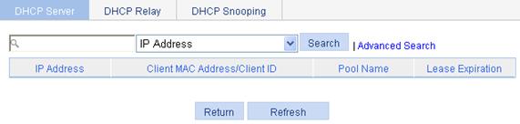
|
Field |
Description |
|
IP Address |
Assigned IP address. |
|
Client MAC Address/Client ID |
Client MAC address or client ID bound to the IP address. |
|
Pool Name |
Name of the DHCP address pool where the IP address belongs. |
|
Lease Expiration |
Lease time of the IP address. |
Recommended configuration procedure (for DHCP relay agent)
|
Step |
Remarks |
|
1. Enabling DHCP and configuring advanced parameters for the DHCP relay agent |
Required. Enable DHCP globally and configure advanced DHCP parameters. By default, global DHCP is disabled. |
|
Required. To improve reliability, you can specify several DHCP servers as a group on the DHCP relay agent and correlate a relay agent interface with the server group. When the interface receives requesting messages from clients, the relay agent will forward them to all the DHCP servers of the group. |
|
|
Required. Enable the DHCP relay agent on an interface, and correlate the interface with a DHCP server group. With DHCP enabled, interfaces work in the DHCP server mode by default.
· An interface cannot serve as both the DHCP server and the DHCP relay agent. The latest configuration takes effect. · If the DHCP relay agent is enabled on an Ethernet subinterface, a packet received from a client on this interface must contain a VLAN tag and the VLAN tag must be the same as the VLAN ID of the subinterface; otherwise, the packet is discarded. · The DHCP relay agent works on interfaces with IP addresses manually configured only. · If an Ethernet subinterface serves as a DHCP relay agent, it conveys IP addresses only to subinterfaces of DHCP clients. In this case, a PC cannot obtain an IP address as a DHCP client. |
|
|
Optional. Create a static IP-to-MAC binding, and view static and dynamic bindings. The DHCP relay agent can dynamically record clients' IP-to-MAC bindings after clients get IP addresses. It also supports static bindings. In other words, you can manually configure IP-to-MAC bindings on the DHCP relay agent, so that users can access external network using fixed IP addresses. By default, no static binding is created. |
Enabling DHCP and configuring advanced parameters for the DHCP relay agent
1. Select Network > DHCP from the navigation tree.
2. Click the DHCP Relay tab to enter the page as shown in Figure 57.
Figure 57 DHCP relay agent configuration page
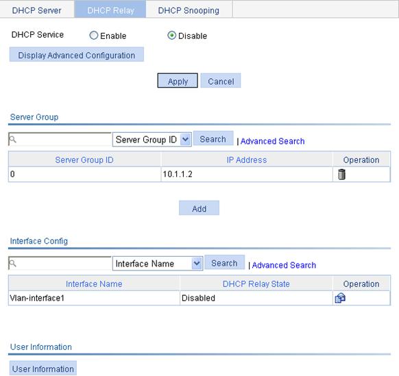
3. Select the Enable option for DHCP Service.
4. Click Display Advanced Configuration to expand the advanced DHCP relay agent configuration field, as shown in Figure 58.
Figure 58 Advanced DHCP relay agent configuration field
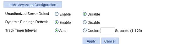
5. Configure the advanced DHCP relay agent parameters as described in Table 19.
6. Click Apply. You must also click Apply for enabling the DHCP service.
|
Item |
Description |
|
Unauthorized Server Detect |
Enable or disable unauthorized DHCP server detection. There are unauthorized DHCP servers on networks, which reply DHCP clients with wrong IP addresses. With this feature enabled, upon receiving a DHCP request, the DHCP relay agent will record the IP address of any DHCP server that assigned an IP address to the DHCP client and the receiving interface. The administrator can use this information to check out DHCP unauthorized servers. The device puts a record once for each DHCP server. The administrator needs to find unauthorized DHCP servers from the log information. After the information of recorded DHCP servers is cleared, the relay agent will re-record server information following this mechanism. |
|
Dynamic Bindings Refresh |
Enable or disable periodic refresh of dynamic client entries, and set the refresh interval. Via the DHCP relay agent, a DHCP client sends a DHCP-RELEASE unicast message to the DHCP server to relinquish its IP address. In this case the DHCP relay agent simply conveys the message to the DHCP server, thus it does not remove the IP address from dynamic client entries. To solve this problem, the periodic refresh of dynamic client entries feature is introduced. With this feature, the DHCP relay agent uses the IP address of a client and the MAC address of the DHCP relay agent interface to periodically send a DHCP-REQUEST message to the DHCP server. · If the server returns a DHCP-ACK message or does not return any message within a specified interval, which means that the IP address is assignable now, the DHCP relay agent will age out the client entry. · If the server returns a DHCP-NAK message, which means the IP address is still in use, the relay agent will not age it out. If the Auto option is selected, the refresh interval is calculated by the relay agent according to the number of client entries.. |
|
Track Timer Interval |
Creating a DHCP server group
1. Select Network > DHCP from the navigation tree.
2. Click the DHCP Relay tab to enter the page as shown in Figure 57.
3. In the Server Group field, click Add to enter the page as shown in Figure 59.
Figure 59 Creating a server group

4. Specify the DHCP server group information as described in Table 20.
5. Click Apply.
|
Item |
Description |
|
Server Group ID |
Enter the ID of a DHCP server group. You can create up to 20 DHCP server groups. |
|
IP Address |
Enter the IP address of a server in the DHCP server group. The server IP address cannot be on the same subnet as the IP address of the DHCP relay agent. Otherwise, the client cannot obtain an IP address. |
Enabling the DHCP relay agent on an interface
1. Select Network > DHCP from the navigation tree.
2. Click the DHCP Relay tab to enter the page as shown in Figure 57.
3.
In the Interface Config field, click the ![]() icon of a specific
interface to enter the page as shown
in Figure 60.
icon of a specific
interface to enter the page as shown
in Figure 60.
Figure 60 Configuring a DHCP relay agent interface
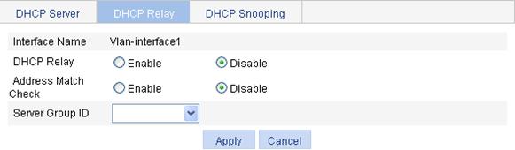
4. Configure the parameters as described in Table 21.
5. Click Apply.
|
Item |
Description |
|
Interface Name |
This field displays the name of a specific interface. |
|
DHCP Relay |
Enable or disable the DHCP relay agent on the interface. If the DHCP relay agent is disabled, the DHCP server is enabled on the interface. |
|
Address Match Check |
Enable or disable IP address check. With this function enabled, the DHCP relay agent checks whether a requesting client's IP and MAC addresses match a binding (dynamic or static) on the DHCP relay agent. If not, the client cannot access outside networks via the DHCP relay agent. This prevents invalid IP address configuration. |
|
Server Group ID |
Correlate the interface with a DHCP server group. A DHCP server group can be correlated with multiple interfaces. |
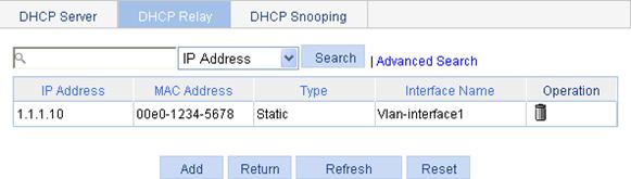
Configuring and displaying clients' IP-to-MAC bindings
1. Select Network > DHCP from the navigation tree
2. Click the DHCP Relay tab to enter the page as shown in Figure 57.
3. In the User Information field, click User Information to view static and dynamic bindings, as shown in Figure 61.
Figure 61 Displaying clients' IP-to-MAC bindings
4. Click Add to enter the page shown in Figure 62.
Figure 62 Creating a static IP-to-MAC binding
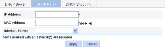
5. Configure static IP-to-MAC binding as described in Table 22.
6. Click Apply.
|
Item |
Description |
|
IP Address |
Enter the IP address of a DHCP client. |
|
MAC Address |
Enter the MAC address of the DHCP client. |
|
Interface Name |
Select the Layer 3 interface connected with the DHCP client.
The interface of a static binding entry must be configured as a DHCP relay agent. Otherwise, address entry conflicts may occur. |
Recommended configuration procedure (for DHCP snooping)
|
Step |
Remarks |
|
Required. By default, DHCP snooping is disabled. |
|
|
Required. Specify an interface as trusted and configure DHCP snooping to support Option 82. By default, an interface is untrusted and DHCP snooping does not support Option 82.
You need to specify the ports connected to the authorized DHCP servers as trusted to make sure that DHCP clients can obtain valid IP addresses. The trusted port and the port connected to the DHCP client must be in the same VLAN. |
|
|
Optional. Display clients' IP-to-MAC bindings recorded by DHCP snooping. |
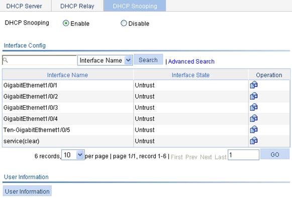
Enabling DHCP snooping
1. Select Network > DHCP from the navigation tree.
2. Click the DHCP Snooping tab to enter the page as shown in Figure 63.
3. Select the Enable option for DHCP Snooping.
Figure 63 DHCP snooping configuration page
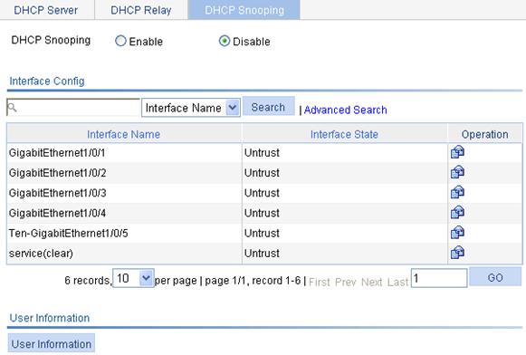
Configuring DHCP snooping functions on an interface
1. Select Network > DHCP from the navigation tree.
2. Click the DHCP Snooping tab to enter the page as shown in Figure 63.
3.
In the Interface Config
field, click the ![]() icon of a specific
interface to enter the page as shown
in Figure 64.
icon of a specific
interface to enter the page as shown
in Figure 64.
Figure 64 DHCP snooping interface configuration page
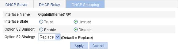
4. Configure the parameters as described in Table 23.
5. Click Apply.
|
Item |
Description |
|
Interface Name |
This field displays the name of a specific interface. |
|
Interface State |
Configure the interface as trusted or untrusted. |
|
Option 82 Support |
Configure DHCP snooping to support Option 82 or not. |
|
Option 82 Strategy |
Select the handling strategy for DHCP requests containing Option 82. The strategies include: · Drop—The message is discarded if it contains Option 82. · Keep—The message is forwarded without its Option 82 being changed. · Replace—The message is forwarded after its original Option 82 is replaced with the Option 82 padded in normal format. |
Displaying clients' IP-to-MAC bindings
1. Select Network > DHCP from the navigation tree.
2. Click the DHCP Snooping tab to enter the page as shown in Figure 63.
3. Click User Information to enter the DHCP snooping user information page, as shown in Figure 65.
Figure 65 DHCP snooping user information
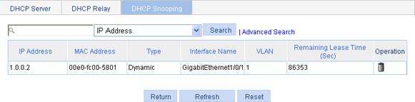
4. View clients' IP-to-MAC bindings recorded by DHCP snooping as described in Table 24.
|
Item |
Description |
|
IP Address |
This field displays the IP address assigned by the DHCP server to the client. |
|
MAC Address |
This field displays the MAC address of the client. |
|
Type |
This field displays the client type, which can be: · Dynamic—The IP-to-MAC binding is generated dynamically. · Static—The IP-to-MAC binding is configured manually. Currently, static bindings are not supported. |
|
Interface Name |
This field displays the device interface to which the client is connected. |
|
VLAN |
This field displays the VLAN to which the device belongs. |
|
Remaining Lease Time |
This field displays the remaining lease time of the IP address. |
DHCP server configuration example
Network requirements
As shown in Figure 66, the DHCP client on subnet 10.1.1.0/24 obtains an IP address dynamically from the DHCP server (AC). The IP address of VLAN-interface 2 of the AC is 10.1.1.1/24.
In subnet 10.1.1.0/24, the address lease duration is ten days and twelve hours and the gateway address is 10.1.1.1.
Configuration procedure
1. Enable DHCP:
a. Select Network > DHCP from the navigation tree to enter the default DHCP Server page.
b. Select the Enable option for DHCP Service.
Figure 67 Enabling DHCP
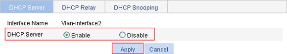
2. Enable the DHCP server on VLAN-interface 2: (This operation can be omitted because the DHCP server is enabled on the interface by default.)
a. In the Interface Config field, click the ![]() icon of VLAN-interface 2.
icon of VLAN-interface 2.
b. Select the Enable option for DHCP Server.
c. Click Apply.
Figure 68 Enabling the DHCP server on VLAN-interface 2
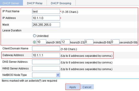
3. Configure a dynamic address pool for the DHCP server:
a. Select the Dynamic option in the Address Pool field (default setting), and click Add.
b. On the page that appears, enter test for IP Pool Name, enter 10.1.1.0 for IP Address, enter 255.255.255.0 for Mask, enter 10 days 12 hours 0 minutes 0 seconds for Lease Duration, and enter 10.1.1.1 for Gateway Address.
c. Click Apply.
Figure 69 Configuring a dynamic address pool for the DHCP server
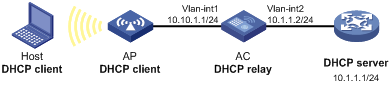
DHCP relay agent configuration example
Network requirements
As shown in Figure 70, VLAN-interface 1 on the DHCP relay agent (AC) connects to the network where DHCP clients reside. The IP address of VLAN-interface 1 is 10.10.1.1/24 and the IP address of VLAN-interface 2 is 10.1.1.1/24. VLAN-interface 2 is connected to the DHCP server whose IP address is 10.1.1.1/24.
The AC forwards messages between DHCP clients and the DHCP server.
Configuration procedure
|
|
NOTE: Because the DHCP relay agent and server are on different subnets, you must configure a static route or dynamic routing protocol so they can communicate. |
1. Enable DHCP:
a. Select Network > DHCP from the navigation tree.
b. Click the DHCP Relay tab.
c. Select the Enable option for DHCP Service.
d. Click Apply.
Figure 71 Enabling DHCP

2. Configure a DHCP server group:
a. In the Server Group field, click Add.
b. Enter 1 for Server Group ID, and 10.1.1.1 for IP Address.
c. Click Apply.
Figure 72 Adding a DHCP server group

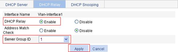
3. Enable the DHCP relay agent on VLAN-interface 1:
a. In the Interface Config field, click the ![]() icon of VLAN-interface 1.
icon of VLAN-interface 1.
b. Select the Enable option for DHCP Relay, and select 1 for Server Group ID.
c. Click Apply.
Figure 73 Enabling the DHCP relay agent on an interface and correlate it with a server group
DHCP snooping configuration example
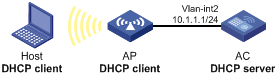
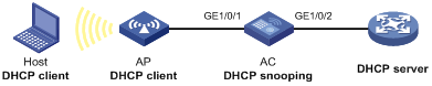
Network requirements
As shown in Figure 74, a DHCP snooping device (AC) is connected to a DHCP server through GigabitEthernet 1/0/2, and to an AP through GigabitEthernet 1/0/1.
· Enable DHCP snooping on the AC and configure DHCP snooping to support Option 82. Configure the handling strategy for DHCP requests containing Option 82 as replace.
· Enable GigabitEthernet 1/0/2 to forward DHCP server responses; disable GigabitEthernet 1/0/1 from forwarding DHCP server responses.
· Configure the AC to record clients' IP-to-MAC address bindings in DHCP-REQUEST messages and DHCP-ACK messages received from a trusted port.
Configuration procedure
1. Enable DHCP snooping:
a. Select Network > DHCP from the navigation tree.
b. Click the DHCP Snooping tab.
c. Select the Enable option for DHCP Snooping.
Figure 75 Enabling DHCP snooping
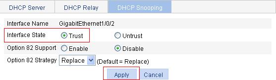
2. Configure DHCP snooping functions on GigabitEthernet 1/0/2:
a. Click the ![]() icon of GigabitEthernet 1/0/2 on the interface list.
icon of GigabitEthernet 1/0/2 on the interface list.
b. Select the Trust option for Interface State.
c. Click Apply.
Figure 76 Configuring DHCP snooping functions on GigabitEthernet 1/0/2
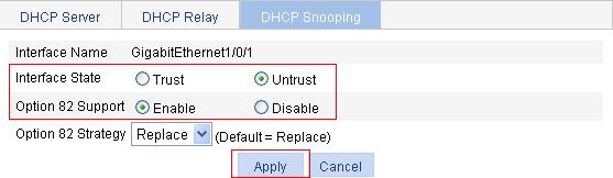
3. Configure DHCP snooping functions on GigabitEthernet 1/0/1.
a. Click the ![]() icon of GigabitEthernet 1/0/1 on the interface list.
icon of GigabitEthernet 1/0/1 on the interface list.
b. To configure the DHCP snooping functions on the interface:
¡ Select the Untrust option for Interface State.
¡ Select the Enable option for Option 82 Support.
¡ Select Replace from the Option 82 Strategy list.
c. Click Apply.
Figure 77 Configuring DHCP snooping functions on GigabitEthernet 1/0/1
Overview
Domain Name System (DNS) is a distributed database used by TCP/IP applications to translate domain names into corresponding IP addresses. With DNS, you can use easy-to-remember domain names in some applications and let the DNS server translate them into correct IP addresses.
There are two types of DNS services, static and dynamic. After a user specifies a name, the device checks the local static name resolution table for an IP address. If no IP address is available, it contacts the DNS server for dynamic name resolution, which takes more time than static name resolution. Therefore, some frequently queried name-to-IP address mappings are stored in the local static name resolution table to improve efficiency.
Static domain name resolution
Configuring static domain name resolution is to set up mappings between domain names and IP addresses manually. IP addresses of the corresponding domain names can be found in the static domain resolution table when you use applications such as telnet.
Dynamic domain name resolution
Dynamic domain name resolution is implemented by querying the DNS server.
DNS proxy
A DNS proxy forwards DNS requests and replies between DNS clients and a DNS server.
A DNS client considers the DNS proxy as the DNS server and sends a DNS request to the DNS proxy, which forwards the request to the designated DNS server, and conveys the reply from the DNS server to the client.
The DNS proxy simplifies network management. When the DNS server address is changed, you only need to change the configuration on the DNS proxy instead of on each DNS client.
For more information about DNS, see H3C WX Series Access Controllers Layer 3 Configuration Guide.
Recommended configuration procedure
Configuring static name resolution table
|
Step |
Remarks |
|
Required. By default, no host name-to-IP address mappings are configured in the static domain name resolution table. |
Configuring dynamic domain name resolution
|
Step |
Remarks |
|
Required. This function is disabled by default. |
|
|
Required. Not configured by default. |
|
|
Optional. Not configured by default. |
|
|
Optional. |
Configuring DNS proxy
|
Step |
Remarks |
|
Required. By default, the device is not a DNS proxy. |
|
|
Required. Not configured by default. |
Configuring static name resolution table
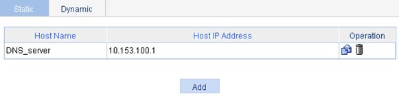
1. Select Network > DNS from the navigation tree to enter the default static domain name resolution configuration page shown in Figure 78.
Figure 78 Static domain name resolution configuration page
2. Click Add to enter the page shown in Figure 79.
Figure 79 Creating a static domain name resolution entry
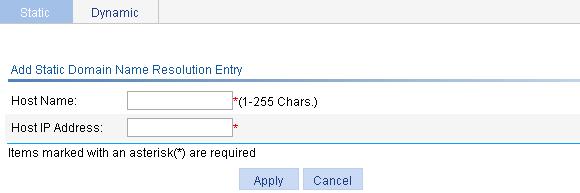
3. Configure the parameters as described in Table 25.
4. Click Apply.
|
Item |
Description |
|
Host Name |
Configure the mapping between a host name and an IP address in the static domain mane table. Each host name corresponds to only one IP address. If you configure multiple IP addresses for a host name, the last configured one takes effect.. |
|
Host IP Address |
Configuring dynamic domain name resolution
1. Select Network > DNS from the navigation tree.
2. Click the Dynamic tab to enter the page shown in Figure 80.
3. Select the Enable option for Dynamic DNS.
4. Click Apply.
Figure 80 Dynamic domain name resolution configuration page
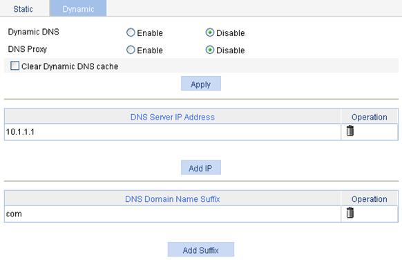
Configuring DNS proxy
1. Select Network > DNS from the navigation tree.
2. Click the Dynamic tab to enter the page shown in Figure 80.
3. Select the Enable option for DNS Proxy.
4. Click Apply.
Adding a DNS server address
1. Select Network > DNS from the navigation tree.
2. Click the Dynamic tab to enter the page shown in Figure 80.
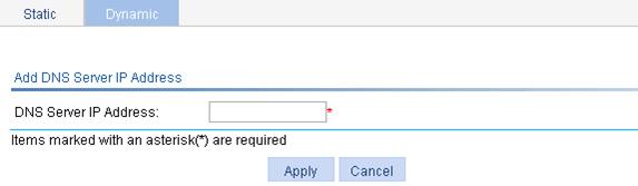
3. Click Add IP to enter the page shown in Figure 81.
4. Enter an IP address in DNS Server IP address field.
5. Click Apply.
Figure 81 Adding a DNS server address
Adding a domain name suffix
1. Select Network > DNS from the navigation tree.
2. Click the Dynamic tab to enter the page shown in Figure 80.
3. Click Add Suffix to enter the page shown in Figure 82.
4. Enter a DNS suffix in the DNS Domain Name Suffix field.
5. Click Apply.
Figure 82 Adding a domain name suffix
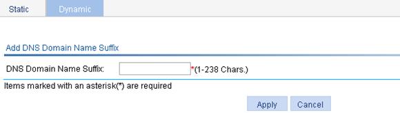
Clearing dynamic DNS cache
1. Select Network > DNS from the navigation tree.
2. Click the Dynamic tab to enter the page shown in Figure 80.
3. Select the Clear Dynamic DNS cache box.
4. Click Apply.
DNS configuration example
Network requirements
As shown in Figure 83, the AC wants to access the host by using an easy-to-remember domain name rather than an IP address, and to request the DNS server on the network for an IP address by using dynamic domain name resolution. The IP address of the DNS server is 2.1.1.2/16 and the DNS server has a com domain, which stores the mapping between domain name host and IP address 3.1.1.1/16.
AC serves as a DNS client, and uses dynamic domain name resolution and the suffix to access the host with the domain name host.com and the IP address 3.1.1.1/16.
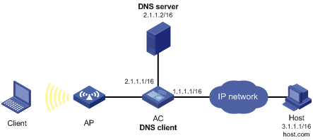
|
|
NOTE: · Before performing the following configuration, make sure that the AC and the host are reachable to each another, and the IP addresses of the interfaces are configured as shown in Figure 83. · This configuration may vary with DNS servers. The following configuration is performed on a PC running Windows Server 2000. |
Configuring the DNS server
1. Create zone com:
a. Select Start > Programs > Administrative Tools > DNS.
b. As shown in Figure 84, right click Forward Lookup Zones and select New Zone.
c. Follow the instructions to create a new zone named com.
Figure 84 Creating a zone
2. Create a mapping between host name and IP address:
a. In Figure 85, right click zone com, and then select New Host.

b. In the dialog box as shown in Figure 86, enter host name host and IP address 3.1.1.1.
c. Click Add Host.
Figure 86 Adding a mapping between domain name and IP address

Configuring the AC
1. Enable dynamic domain name resolution.
a. Select Network > DNS from the navigation tree.
b. Click the Dynamic tab
c. Select the Enable option for Dynamic DNS, as shown in Figure 87.
d. Click Apply.
Figure 87 Enabling dynamic domain name resolution
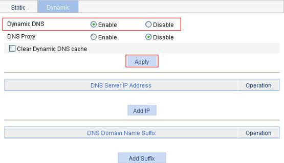
2. Configure the DNS server address:
a. Click Add IP in Figure 87 to enter the page for adding a DNS server IP address.
b. Enter 2.1.1.2 for DNS Server IP Address, as shown in Figure 88.
c. Click Apply.
Figure 88 Adding a DNS server address
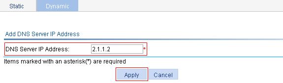
3. Configure the domain name suffix:
· Click Add Suffix in Figure 87.
· Enter com for DNS Domain Name Suffix, as shown in Figure 89.
· Click Apply.
Figure 89 Adding a DNS domain name suffix
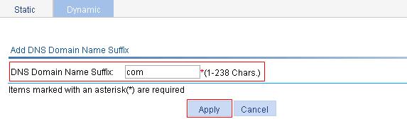
Verifying the configuration
Use the ping host command on the AC to verify that the communication between the AC and the host is normal and that the corresponding destination IP address is 3.1.1.1.
1. Select Diagnostic Tools > Ping from the navigation tree to enter the IPv4 Ping configuration page.
2. Enter host in the Destination IP address or host name field.
3. Click Start to execute the ping command
4. View the result in the Summary field.
Figure 90 Ping operation
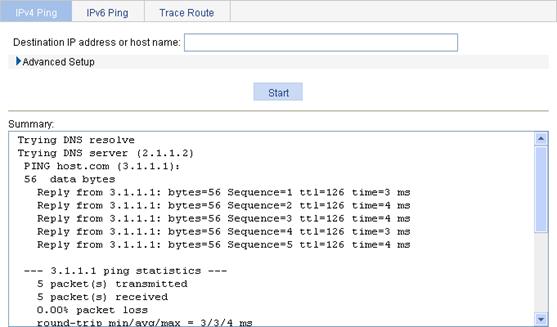
Overview
The service management module provides the following types of services: FTP, Telnet, SSH, SFTP, HTTP and HTTPS. You can enable or disable the services as needed. In this way, the performance and security of the system can be enhanced, thus secure management of the device can be achieved.
The service management module also provides the function to modify HTTP and HTTPS port numbers, and the function to associate the FTP, HTTP, or HTTPS service with an ACL, thus reducing attacks of illegal users on these services.
FTP service
The File Transfer Protocol (FTP) is an application layer protocol for sharing files between server and client over a TCP/IP network.
Telnet service
The Telnet protocol is an application layer protocol that provides remote login and virtual terminal functions on the network.
SSH service
Secure Shell (SSH) offers an approach to securely logging in to a remote device. By encryption and strong authentication, it protects devices against attacks such as IP spoofing and plain text password interception.
SFTP service
The secure file transfer protocol (SFTP) is a new feature in SSH2.0. SFTP uses the SSH connection to provide secure data transfer. The device can serve as the SFTP server, allowing a remote user to log in to the SFTP server for secure file management and transfer. The device can also serve as an SFTP client, enabling a user to login from the device to a remote device for secure file transfer.
HTTP service
The Hypertext Transfer Protocol (HTTP) is used for transferring web page information across the Internet. It is an application-layer protocol in the TCP/IP protocol suite.
You can log in to the device using the HTTP protocol with HTTP service enabled, accessing and controlling the device with Web-based network management.
HTTPS service
The Secure HTTP (HTTPS) refers to the HTTP protocol that supports the Security Socket Layer (SSL) protocol.
The SSL protocol of HTTPS enhances the security of the device in the following ways:
· Uses the SSL protocol to ensure the legal clients to access the device securely and prohibit the illegal clients;
· Encrypts the data exchanged between the HTTPS client and the device to ensure the data security and integrity, realizing the security management of the device;
· Defines certificate attribute-based access control policy for the device to control the access right of the client, in order to further avoid attacks from illegal clients.
Configuring service management
1. Select Network > Service from the navigation tree to enter the service management configuration page, as shown in Figure 91.
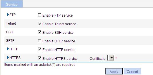
2. Enable or disable various services on the page as described in Table 26.
3. Click Apply.
|
Item |
Description |
|
|
FTP |
Enable FTP service |
Specify whether to enable the FTP service. The FTP service is disabled by default. |
|
ACL |
Associate the FTP service with an ACL. Only the clients that pass the ACL filtering are permitted to use the FTP service. You can view this configuration item by clicking the expanding button in front of FTP. |
|
|
Telnet |
Enable Telnet service |
Specify whether to enable the Telnet service. The Telnet service is enabled by default. |
|
SSH |
Enable SSH service |
Specify whether to enable the SSH service. The SSH service is disabled by default. |
|
SFTP |
Enable SFTP service |
Specify whether to enable the SFTP service. The SFTP service is disabled by default.
When you enable the SFTP service, the SSH service must be enabled. |
|
HTTP |
Enable HTTP service |
Specify whether to enable the HTTP service. The HTTP service is disabled by default. |
|
Port Number |
Set the port number for HTTP service. You can view this configuration item by clicking the expanding button in front of HTTP.
When you modify a port, make sure that the port is not used by other service. |
|
|
ACL |
Associate the HTTP service with an ACL. Only the clients that pass the ACL filtering are permitted to use the HTTP service. You can view this configuration item by clicking the expanding button in front of HTTP. |
|
|
HTTPS |
Enable HTTPS service |
Specify whether to enable the HTTPS service. The HTTPS service is disabled by default. |
|
Port Number |
Set the port number for HTTPS service. You can view this configuration item by clicking the expanding button in front of HTTPS.
When you modify a port, make sure that the port is not used by other service. |
|
|
ACL |
Associate the HTTPS service with an ACL. Only the clients that pass the ACL filtering are permitted to use the HTTPS service. You can view this configuration item by clicking the expanding button in front of HTTPS. |
|
|
Certificate |
Set the local certificate for the HTTPS service. The list displays certificate subjects. You can configure the available PKI domains by selecting Authentication > Certificate Management from the navigation tree at the left side of the interface. For more information, see "Certificate management."
The service management, portal authentication and local EAP service modules always reference the same PKI domain. Changing the referenced PKI domain in any of the three modules also changes that referenced in the other two modules. |
|
Ping
You can use the ping function to check whether a device with a specified address is reachable, and to examine network connectivity.
A successful execution of the ping command involves the following steps:
1. The source device sends an ICMP echo request (ECHO-REQUEST) to the destination device.
2. The destination device responds by sending an ICMP echo reply (ECHO-REPLY) to the source device after receiving the ICMP echo request.
3. The source device displays related statistics after receiving the reply.
Output of the ping command falls into the following:
· The ping command can be applied to the destination's host name or IP address. If the destination's host name is unknown, the prompt information is displayed.
· If the source device does not receive an ICMP echo reply within the timeout time, it displays the prompt information and the statistics during the ping operation. If the source device receives an ICMP echo reply within the timeout time, it displays the number of bytes of the echo reply, the message sequence number, Time to Live (TTL), the response time, and the statistics during the ping operation. Statistics during the ping operation include number of packets sent, number of echo reply messages received, percentage of messages not received, and the minimum, average, and maximum response time.
Trace route
By using the trace route command, you can display the Layer 3 devices involved in delivering a packet from source to destination. This function is useful for identification of failed node(s) in the event of network failure.
The trace route command involves the following steps in its execution:
1. The source device sends a packet with a TTL value of 1 to the destination device.
2. The first hop (the Layer 3 device that first receives the packet) responds by sending a TTL-expired ICMP message to the source, with its IP address encapsulated. In this way, the source device can get the address of the first Layer 3 device.
3. The source device sends a packet with a TTL value of 2 to the destination device.
4. The second hop responds with a TTL-expired ICMP message, which gives the source device the address of the second Layer 3 device.
5. This process continues until the ultimate destination device is reached. In this way, the source device can trace the addresses of all the Layer 3 devices involved to get to the destination device.
The traceroute command can be applied to the destination's host name or IP address. If the destination's host name is unknown, the prompt information is displayed.
Ping operation
IPv4 ping operation
1. Select Diagnostic Tools > Ping from the navigation tree to enter the IPv4 Ping configuration page.
2. Click the expansion button before Advanced Setup to display the configurations of the advanced parameters of IPv4 ping operation, as shown in Figure 92.
Figure 92 IPv4 ping configuration page
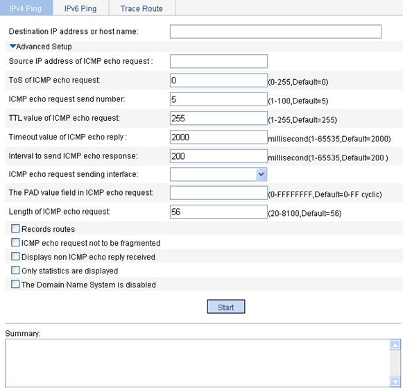
3. Enter the IPv4 address or host name of the destination device in the Destination IP address or host name field.
4. Set the advanced parameters for the IPv4 ping operation.
5. Click Start to execute the ping command.
6. View the result in the Summary field.
Figure 93 IPv4 ping operation results
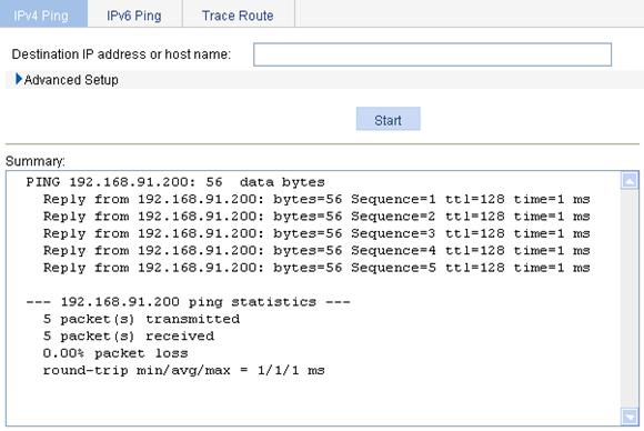
IPv6 ping operation
1. Select Diagnostic Tools > Ping from the navigation tree.
2. Enter the IPv6 ping configuration page (default setting).
3. Expand Advanced Setup to display the configurations of the advanced parameters of IPv6 ping operation, as shown in Figure 94.
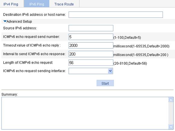
4. Enter the IPv6 address or host name of the destination device in the Destination IP address or host name field.
5. Set the advanced parameters for the IPv6 ping operation.
6. Click Start to execute the ping command.
7. View the result in the Summary field, as shown in Figure 95.
Figure 95 IPv6 ping operation results
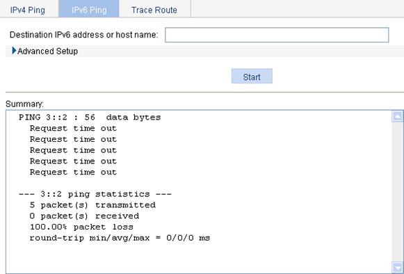
Trace route operation
|
|
NOTE: · The web interface does not support trace route on IPv6 addresses. · Before performing the trace route operations, execute the ip ttl-expires enable command on the intermediate device to enable the sending of ICMP timeout packets and the ip unreachables enable command on the destination device to enable the sending of ICMP destination unreachable packets. |
1. Select Diagnostic Tools > Trace Route from the navigation tree.
2. Click the Trace Route tab to enter the Trace Route configuration page, as shown in Figure 96.
Figure 96 Trace Route configuration page
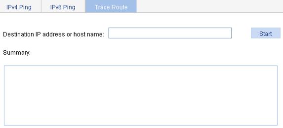
3. Enter the destination IP address or host name.
4. Click Start to execute the trace route command.
5. View the result in the Summary field, as shown in Figure 97.
Figure 97 Trace route operation results