- Table of Contents
-
- H3C WX Series Access Controllers Web-Based Configuration Guide(R3308 R2308)-6W107
- 00-Preface
- 01-About the WX Series Access Controllers Web Configuration Guide
- 02-Quick Start
- 03-Web Overview
- 04-Summary
- 05-Device
- 06-Network
- 07-AP Configuration
- 08-Wireless Service
- 09-WLAN Roaming Configuration
- 10-Radio Configuration
- 11-Authentication
- 12-Security
- 13-QoS configuration
- 14-Advanced Settings
- 15-Stateful Failover Configuration
- Related Documents
-
| Title | Size | Download |
|---|---|---|
| 02-Quick Start | 164.79 KB |
Quick start wizard home page
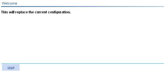
From the navigation tree, select Quick Start to enter the home page of the Quick Start wizard, as shown in Figure 1.
Figure 1 Home page of the quick start wizard
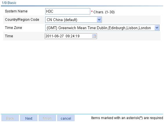
Basic configuration
On the home page of the Quick Start wizard, click start to enter the basic configuration page, as shown in Figure 2.
Figure 2 Basic configuration page
|
Item |
Description |
|
System Name |
Specify the name of the current device. By default, the system name of the device is H3C. |
|
Country/Region Code |
Select the code of the country where you are. This field defines the radio frequency characteristics such as the power and the total number of channels for frame transmission. Before configuring the device, you need to configure the country code correctly. If the Country Code field is grayed out, it cannot be modified. |
|
Time Zone |
Select a time zone for the system. |
|
Time |
Specify the current time and date. |
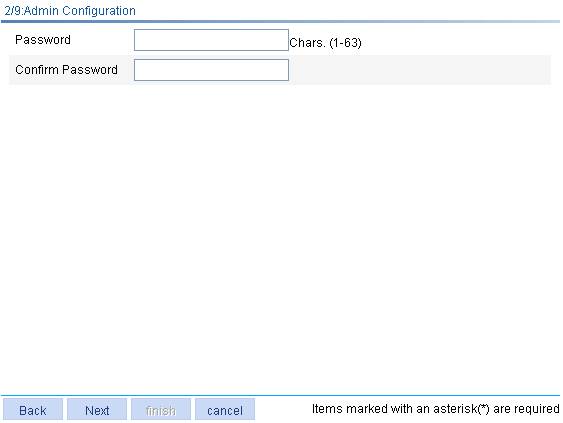
Admin configuration
On the basic configuration page, click Next to enter the admin configuration page, as shown in Figure 3.
Figure 3 Admin configuration page
|
Item |
Description |
|
Password |
Specify the password for user Admin to use to log into the device, in cipher text. |
|
Confirm Password |
Enter the password again to confirm the password. |
IP configuration
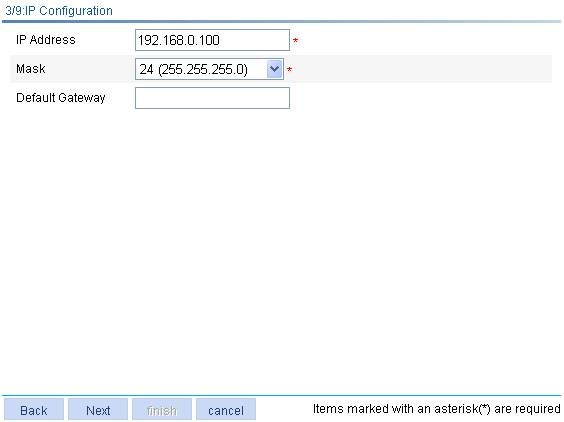
On the Admin Configuration page, click Next to enter the IP configuration page, as shown in Figure 4.
Figure 4 IP configuration page
|
Item |
Description |
|
IP Address |
Specify the IP address of VLAN-interface 1. This IP address is used for logging into the device. The default is 192.168.0.100. |
|
Mask |
Specify the IP address mask of VLAN-interface 1. By default, the mask is 24-bit long. |
|
Default Gateway |
Specify the IP address of the default gateway that connects the device to the network. By default, the IP address of the default gateway is not specified. |
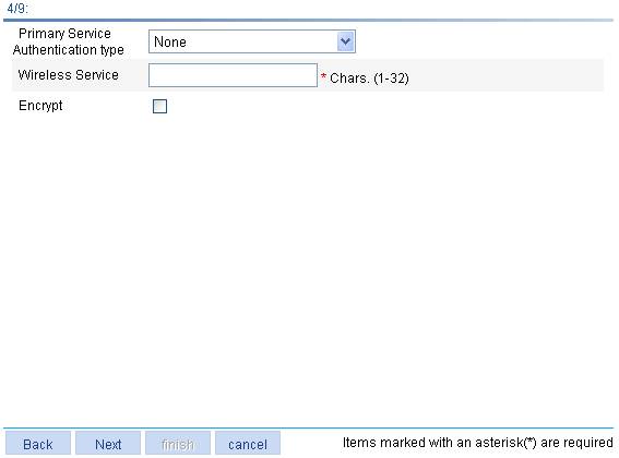
Wireless configuration
On the IP configuration page, click Next to enter the wireless configuration page, as shown in Figure 5.
Figure 5 Wireless configuration page
|
Item |
Description |
|
Primary Service Authentication type |
Select the authentication type for the wireless service, which can be: · None: Performs no authentication. · User authentication (802.1X): Performs 802.1X authentication. · Portal: Performs Portal authentication. |
|
Wireless Service |
Specify the Service Set Identifier (SSID). |
|
Encrypt |
Select this box to go to the 7/13: Encryption Configuration step. By default, no encryption is performed. If this option is not selected, the 7/13: Encryption Configuration step is skipped. |
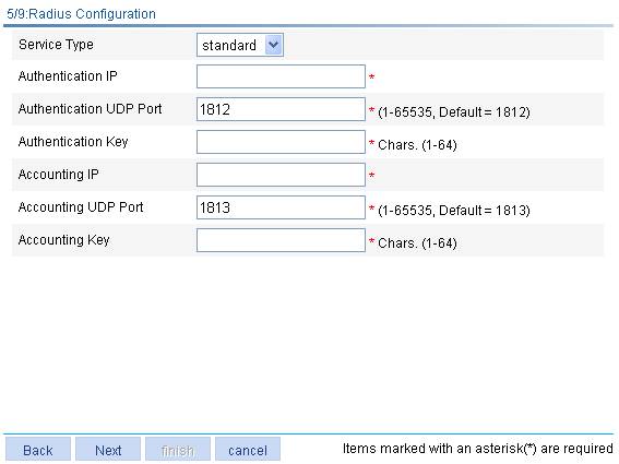
RADIUS configuration
On the wireless configuration page, select User authentication (802.1X) or Portal for the Primary Service Authentication Type field, and then click Next to enter the RADIUS configuration page, as shown in Figure 6.
Figure 6 RADIUS configuration page
|
Item |
Description |
|
Service Type |
Select the type of the RADIUS server. Two types are available: standard and enhanced: · extended—Specifies extended RADIUS server, which is usually an IMC server. In this case, the RADIUS client (access device) and the RADIUS server exchange packets based on the specifications and packet format definitions of a private RADIUS protocol. · standard—Specifies the standard RADIUS server. In this case, the RADIUS client (access device) and the RADIUS server exchange packets based on the specifications and packet format definitions of the standard RADIUS protocols (RFC 2138, RFC 2139, and the updates). |
|
Authentication IP |
Enter the IP address of the RADIUS authentication server. |
|
Authentication UDP Port |
Enter the port number of the RADIUS authentication server. |
|
Authentication Key |
Enter the shared key of the RADIUS authentication server. |
|
Accounting IP |
Enter the IP address of the RADIUS accounting server. |
|
Accounting UDP Port |
Enter the port number of the RADIUS accounting server. |
|
Accounting Key |
Enter the shared key of the RADIUS accounting server. |
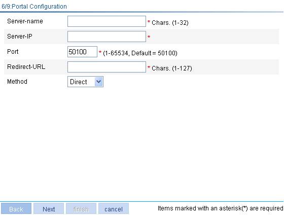
Portal configuration
On the wireless configuration page, select Portal for the Primary Service Authentication Type field, and then click Next to enter the RADIUS configuration page. After you complete RADIUS configuration, click Next to enter the portal configuration page, as shown in Figure 7.
Figure 7 Portal configuration page
|
Item |
Description |
|
Server-name |
Specify the system name of the portal server. |
|
Server-IP |
Enter the IP address of the portal server. |
|
Port |
Enter the port number of the portal server. |
|
Redirect-URL |
Enter the URL of the portal authentication server. |
|
Method |
Specify the portal authentication method to be used, which can be: · Direct—Before authentication, a user manually configures an IP address or directly obtains a public IP address through DHCP, and can access only the portal server and predefined free websites. After passing authentication, the user can access the network resources. The authentication process of direct authentication is relatively simple than that of the re-DHCP authentication. · Layer3—Layer 3 authentication is similar to direct authentication but allows Layer 3 forwarding devices to be present between the authentication client and the access device. · Redhcp—Before authentication, a user gets a private IP address through DHCP and can access only the portal server and predefined free websites. After passing authentication, the user is allocated a public IP address and can access the network resources. |
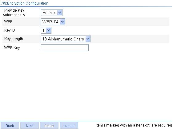
Encryption configuration
On the wireless configuration page, select User authentication (802.1X) for Primary Service Authentication Type and click Next to enter the encryption configuration page, as shown in Figure 8.
Figure 8 Encryption configuration page
|
Item |
Description |
|
Provide Key Automatically |
Specify whether to use WEP keys provided automatically or use static WEP keys. · Enable: Use WEP keys provided automatically. · Disable: Use static WEP keys. By default, static WEP keys are used. After you select Enable, WEP104 is displayed for WEP.
Automatically provided WEP keys must be used together with 802.1X authentication. Therefore, This option is available only after you select User authentication (802.1X) for Primary Service Authentication type on the wireless configuration page. |
|
WEP |
Select the key type of the WEP encryption mechanism, which can be WEP40, WEP104 and WEP 128. |
|
Key ID |
Select the WEP key index, which can be 1, 2, 3, or 4. Each number represents one of the four static keys of WEP. The selected key index will be used for frame encryption and decryption.
If you select to enable Provide Key Automatically, only 1, 2, and 3 are available for the Key ID option. |
|
Key Length |
Select the key length. · When the key type is WEP40, the key length can be five alphanumeric characters or ten hexadecimal characters. · When the key type is WEP104, the key length can be 13 alphanumeric characters or 26 hexadecimal characters. · When the key type is WEP128, the key length can be 16 alphanumeric characters or 32 hexadecimal characters. |
|
WEP Key |
Enter the WEP key. |
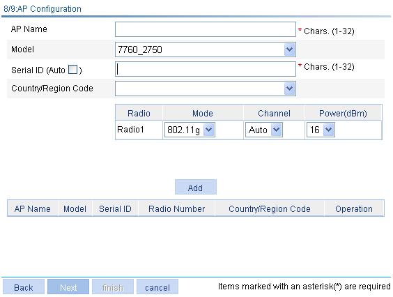
AP configuration
On the guest service configuration page, click Next to enter the AP configuration page, as shown in Figure 9. You can configure an AP and click Add. You can configure multiple APs on the page. The section at the bottom of the page displays all existing APs.
Figure 9 AP configuration page
|
Item |
Description |
|
AP Name |
Enter the name of the AP. |
|
Model |
Select the model of the AP. |
|
Serial ID |
Specify the serial ID of the AP. · If the Auto box is not selected, you need to manually enter a serial ID. · If the Auto box is selected, the AC automatically searches the serial ID of the AP. This option needs to cooperate with the auto AP function to implement automatic AP discovery so that the AP can connect with the AC automatically. If there are a large number of APs, the automatic AP discovery function can avoid repeated configuration of AP serial numbers. For how to configure auto AP, see "AP configuration." |
|
Country/Region Code |
Select a country/region code for the AP. By default, no country/region code is configured for the AP and the AP uses the global country/region code (which is configured on the AC). If the country/region code is specified on this page, the AP uses this configuration. For information about the country/region code configured on the AC, see "Advanced settings." |
|
Radio |
Radio unit of the AP. |
|
Mode |
Select the radio mode. The radio mode depends on the AP model. |
|
Channel |
Select the working channel. The channel list for the radio depends on the country/region code and radio mode, and varies with device models. Auto: Specifies the automatic channel mode. With Auto specified, the AC evaluates the quality of channels in the wireless network, and selects the best channel as the working channel. After the channel is changed, the power list is refreshed. |
|
Power |
Select the transmission power. The maximum power of the radio depends on the country/region code, working channel, AP model, radio mode, and antenna type. If 802.11n is specified as the radio mode, the maximum power of the radio also depends on the bandwidth mode. |
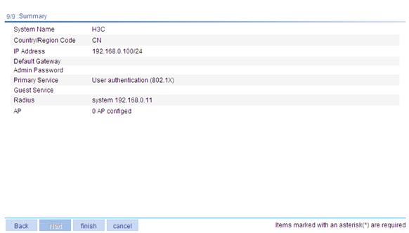
Configuration summary
On the AP configuration page, click Next to enter the configuration summary page, as shown in Figure 10. The configuration summary page displays all configurations you have made. Click finish to save your configurations.
Figure 10 Configuration summary page