- Table of Contents
-
- H3C WX Series Access Controllers Web-Based Configuration Guide(R3308 R2308)-6W107
- 00-Preface
- 01-About the WX Series Access Controllers Web Configuration Guide
- 02-Quick Start
- 03-Web Overview
- 04-Summary
- 05-Device
- 06-Network
- 07-AP Configuration
- 08-Wireless Service
- 09-WLAN Roaming Configuration
- 10-Radio Configuration
- 11-Authentication
- 12-Security
- 13-QoS configuration
- 14-Advanced Settings
- 15-Stateful Failover Configuration
- Related Documents
-
| Title | Size | Download |
|---|---|---|
| 07-AP Configuration | 187.98 KB |
The AP configuration module allows you to perform the following configurations:
· Establish a connection between AC and AP
· Configure auto AP
· Configure an AP group
AC-AP connection
An AP and an AC establish a tunnel connection based on UDP.
An AP uses a data tunnel to encapsulate data packets to be sent to the AC. These packets can be raw 802.11 packets or 802.11 to 802.3 translated packets. An AC provides a control tunnel to support remote AP configuration and management, and WLAN and mobile management.
The AC can dynamically configure an AP based on the information provided by the administrator.
Auto AP
The auto AP feature allows an AP to automatically connect to an AC. When you deploy a wireless network with many APs, the auto AP function avoids configuration of many AP serial IDs, thus simplifying configuration.
AP group
Some wireless service providers need to control the access positions of clients. For example, as shown in the figure below, to meet security or billing needs, it is required to connect wireless clients 1, 2 and 3 to the wired network through APs 1, 2 and 3 respectively. To achieve this, you can configure an AP group that the clients can be associated with and then apply the AP group in a user profile.
Figure 1 Client access control

Configuring an AP
Creating an AP
1. Select AP > AP Setup from the navigation tree.
2. Click Add to enter the page for adding an AP.
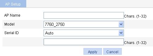
3. Create the AP as described in Table 1.
4. Click Apply.
|
Item |
Description |
|
AP Name |
AP name. |
|
Model |
AP model. |
|
Serial ID |
· Auto—If selected, the AC automatically searches the AP serial ID. This function is used together with the auto AP function. For how to configure auto AP, see "Configuring auto AP." · Manual—If this mode is selected, you need to type an AP serial ID. |
Configuring an AP
1. Select AP > AP Setup from the navigation tree.
2.
Click the ![]() icon corresponding
to the target AP to enter the page for configuring an AP.
icon corresponding
to the target AP to enter the page for configuring an AP.
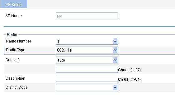
3. Configure the AP as described in Table 2.
4. Click Apply.
|
Item |
Description |
|
AP Name |
Display the name of the AP selected. |
|
Radio Number |
Select the number of the radios on the AP. The value depends on the AP model. |
|
Radio Type |
Select the radio type, which can be one of the following values: · 802.11a. · 802.11b. · 802.11g. · 802.11n (2.4 GHz) · 802.11n (5 GHz) The value depends on the AP model and radio type. |
|
Serial ID |
Set a serial ID for the AP. · Auto—If selected, the AP serial ID is automatically found. This option is used together with the auto AP function. For how to configure auto AP, see "Configuring auto AP." · Manual—You need to enter an AP serial ID.
The serial ID is the unique identity of the AP. If the AP has connected to the AC, changing or deleting its serial ID renders the tunnel down and the AP needs to discover the AC to connect again. |
|
Description |
Description of the AP. |
|
District Code |
By default, no district code is configured for an AP, which uses the global district code. An AP configured with a district code uses its own district code rather than the global one. For how to configure the global district code, see "Advanced settings".
Some ACs and fit APs use locked district codes, whichever is used is determined as follows: · An AC's locked district code cannot be changed, and all managed fit APs whose district codes are not locked must use the AC's locked district code. · A fit AP's locked district code cannot be changed and the fit AP can only use the district code. · If an AC and a managed fit AP use different locked district codes, the fit AP uses its own locked district code. |
Configuring advanced settings
1. Select AP > AP Setup from the navigation tree.
2.
Click the ![]() icon corresponding to the target AP.
icon corresponding to the target AP.
3. On the page that appears, expand Advanced Setup to enter the page for advanced AP setup.
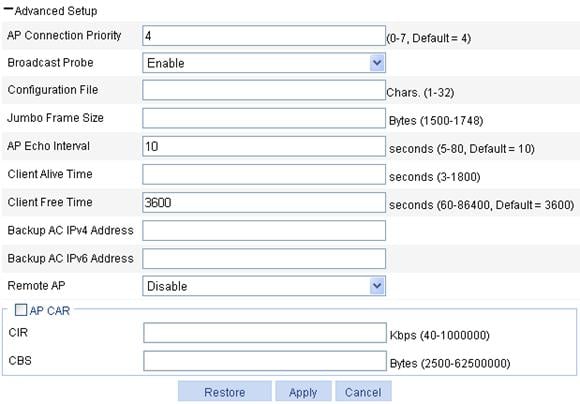
4. Configure advanced settings for the AP as described in Table 3.
5. Click Apply.
|
Item |
Description |
|
|
AP Connection Priority |
AP connection priority. Specify the AP connection priority on the AC. For more information, see "AP connection priority configuration example." It can also be used together with the backup function. For more information, see "Advanced settings." |
|
|
Broadcast Probe |
· Enable—Enable the AP to respond to broadcast probe requests. The AP will respond to broadcast probe requests with the SSID null. · Disable—Disable the AP from responding to broadcast probe requests. The AP will respond to broadcast probe requests with the specified SSID. By default, this option is enabled. |
|
|
Configuration File |
Specify a name for the configuration file in the storage media and maps the specified configuration file to the AP. When local forwarding is enabled, you can use the configuration file to configure the AP. For example, when you configure a user profile when local forwarding is enabled, you must write the user profile, QoS policy, and ACL commands to the configuration file, and download the configuration file to the AP.
The commands in the configuration file must be in their complete form. |
|
|
Jumbo Frame Size |
Set the maximum size of jumbo frames. When this function is enabled, the AC can send frames whose size does not exceed the maximum size to the AP. By default, the AC cannot send jumbo frames to the AP. |
|
|
AP Echo Interval |
Set the interval for sending echo requests. There is a keep-live mechanism between AP and AC, to confirm whether the tunnel is working or not. An AP periodically sends echo requests to an AC. The AC responds to echo requests by sending echo responses, which indicates that the tunnel is up. |
|
|
Client Alive Time |
Set the client keep alive interval. The keep-alive mechanism is used to detect clients segregated from the system due to various reasons such as power failure or crash, and disconnect them from the AP. By default, the client keep-alive functionality is disabled. |
|
|
Client Free Time |
Maximum interval for which the link between the AP and a client can be idle. |
|
|
Backup AC IPv4 Address |
Set the IPv4 address of the backup AC for the AP. |
If you configure the global backup AC information both in Advanced Setup > AC Backup and AP > AP Setup, the configuration in AP > AP Setup takes precedence. For more information about AC backup, see "Advanced settings." |
|
Backup AC IPv6 Address |
Set the IPv6 address of the backup AC for the AP. |
|
|
AP CAR |
Select this box to configure CAR for the AP. By default, no CAR is set for an AP. |
|
|
Remote AP |
· Enable—Enable the remote AP function. · Disable—Disable the remote AP function. By default, the remote AP function is disabled. With this function enabled, when the tunnel between the AP and AC is terminated, the AP automatically enables local forwarding (despite whether or not local forwarding is configured on the AC) to provide wireless access for logged-in clients but not allow new clients. When a tunnel is established between the AP and AC again, the AP automatically switches to the centralized forwarding mode and logs off all clients on the remote AP.
If a tunnel has been established between the remote AP and AC, when the tunnel between the AP and AC is terminated, the remote AP uses the backup tunnel to provide wireless access for logged-in clients. For more information about AC backup, see "Advanced settings." |
|
|
CIR |
Committed information rate, in Kbps. |
|
|
CBS |
Committed burst size, in bits. By default, the CBS is the number of bytes transmitted in 500 ms at the rate of CIR. For example, if CIR is 100, CBS is 50000 bits, or, 6250 bytes by default. |
|
Configuring auto AP
Enabling auto AP
1. Select Advance > Auto AP from the navigation tree.
Figure 5 Configuring auto AP
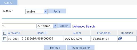
2. Enable auto AP as described in Table 4.
|
Item |
Description |
|
Auto AP |
· enable—Enable the auto AP function. You must also select Auto from the Serial ID list on the AP setup page to use the auto AP function. · disable—Disable the auto AP function. By default, the auto AP function is disabled.
After using the auto AP function, H3C recommends you to disable the auto AP function. |
Renaming an AP
1. After enabling auto AP, click Refresh.
2.
To modify the automatically found AP name, click
the ![]() icon in the Operation column.
icon in the Operation column.
Figure 6 Renaming an AP
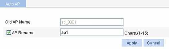
3. On the page that appears, rename the AP as described in Table 5.
4. Click Apply.
|
Item |
Description |
|
Old AP Name |
Display the name of the automatically discovered AP. |
|
AP Rename |
Select the AP Rename check box, and type the new AP name. |
For the example of configuring auto AP, see "Access service configuration."
Batch switch
If you do not need to modify the automatically found AP names, you can select the AP Name box, and then click Transmit All AP to complete auto AP setup.
Configuring an AP group
Creating an AP group
1. Select AP > AP Group from the navigation tree.
2. Click Add.
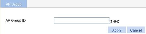
3. Create the AP group as described in Table 6.
|
Item |
Description |
|
AP Group ID |
AP group ID. The value range varies with devices. For more information, see "Feature matrixes." |
Configuring an AP group
1. Select AP > AP Group from the navigation tree.
2.
Click the ![]() icon corresponding to the target AP group to enter the page for configuring
an AP group.
icon corresponding to the target AP group to enter the page for configuring
an AP group.
Figure 8 Configuring an AP group
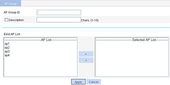
3. Configure the AP group as described in Table 7.
4. Click Apply.
|
Item |
Description |
|
AP Group ID |
Display the ID of the selected AP group. |
|
Description |
Select this option to configure a description for the AP group. |
|
Exist AP List |
Set the APs in the configured AP group. · To add the APs to the Selected AP List, click the APs to be added to the AP group, and click the > button in the AP List area. · To delete the selected APs from the AP group, select the APs to be deleted in the Selected AP List, and click the < button. The APs to be added in AP Group ID should be created by selecting AP > AP Setup first. |
Applying the AP group
Select Authentication > Users from the navigation tree to apply the AP group. For the related configuration, see "Users."
AP connection priority configuration example
Network requirements
Configure a higher AP connection priority on AC 1 to enable the AP to establish a connection with AC 1.
Figure 9 Network diagram
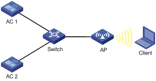
Configuring AC 1
1. Configure AP-related information:
For the detailed configuration, see "Access service configuration."
2. Configure an AP connection priority:
a. Select AP > AP Setup from the navigation tree.
b. Click the ![]() icon corresponding to the target AP to
enter the AP setup page.
icon corresponding to the target AP to
enter the AP setup page.
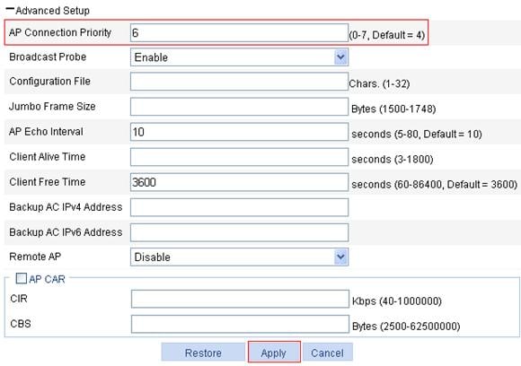
c. Expand Advanced Setup to enter the page shown in Figure 10 and set the AP connection priority to 6.
d. Click Apply.
Figure 10 Configuring AP connection priority
Configuring AC 2
1. Configure AP-related information:
For the detailed configuration, see "Access service configuration."
2. Configure AP connection priority:
Use the default AP connection priority on AC 2.
Verifying the configuration
A higher AP connection priority is configured on AC 1, so AP must establish a connection with AC 1.