- Table of Contents
-
- H3C WX Series Access Controllers Web-Based Configuration Guide(R3308 R2308)-6W107
- 00-Preface
- 01-About the WX Series Access Controllers Web Configuration Guide
- 02-Quick Start
- 03-Web Overview
- 04-Summary
- 05-Device
- 06-Network
- 07-AP Configuration
- 08-Wireless Service
- 09-WLAN Roaming Configuration
- 10-Radio Configuration
- 11-Authentication
- 12-Security
- 13-QoS configuration
- 14-Advanced Settings
- 15-Stateful Failover Configuration
- Related Documents
-
| Title | Size | Download |
|---|---|---|
| 04-Summary | 405.16 KB |
Contents
Displaying detailed information of WLAN service
Displaying statistics of WLAN service
Displaying connection history information of WLAN service
Displaying WLAN service information of an AP
Displaying AP connection history information
Displaying AP radio information
Displaying AP detailed information
Displaying client detailed information
Displaying client roaming information
Displaying RF ping information
Device information
You can view the following information on the Device Info menu:
· Device information
· System resource state
· Device interface information
· Recent system logs (at most five)
After logging in to the Web interface, you enter the Summary > Device Info page.
Figure 1 Device info page

Select the refresh mode from the Refresh Period list.
· If you select a specific refresh period (for example, 1 minute), the system periodically refreshes the Device Info page according to the selected refresh period.
· If you select Manual, you need to click Refresh to refresh the page.
Device info
Table 1 Field description
|
Field |
Description |
|
Device Name |
Display the device model. |
|
Product Information |
Display the product information. |
|
Device Location |
Display the location of the device. To configure the device location information, select Device > SNMP > Setup; for more information, see "SNMP configuration." |
|
Contact Information |
Display the contact information for device maintenance. To configure the contact information, select Device > SNMP > Setup; for more information, see "SNMP configuration." |
|
SerialNum |
Display the serial number of the device. |
|
Software Version |
Display the software version of the device. |
|
Hardware Version |
Display the hardware version of the device. |
|
Bootrom Version |
Display the Boot ROM version of the device. |
|
Running Time |
Display the running time after the latest boot of the device. |
System resource state
|
Field |
Description |
|
CPU Usage |
Display the real-time CPU usage. |
|
Memory Usage |
Display the real-time memory usage and the total memory size. |
|
Temperature |
Display the temperature of the device. |
Device interface information
|
Field |
Description |
|
Interface |
Display interface name and interface number. |
|
IP Address/Mask |
Display the IP address and mask of an interface. |
|
Status |
Display interface status. ·
·
·
|
|
|
NOTE: For more information about device interfaces, click the More hyperlink under the Device Interface Information area to enter the Device > Interface page to view and operate the interfaces. For more information, see "Interface management." |
Recent system logs
|
Field |
Description |
|
Time |
Display the time when the system logs are generated. |
|
Level |
Display the level of the system logs. |
|
Description |
Display the contents of the system logs. |
|
|
NOTE: For more information about system logs, click the More hyperlink under the Recent System Operation Logs area to enter the Device > Syslog > Loglist page to view the logs. For more information, see "Log management." |
Displaying WLAN service
1. Select Summary > Wireless Service from the navigation tree
2. Click the specified WLAN service to view the detailed information, statistics, or connection history.
Displaying detailed information of WLAN service
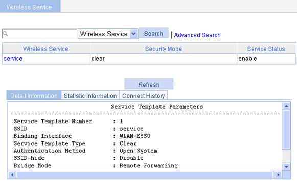
The detailed information of WLAN service (clear type) is as shown in Figure 2. For the description of the fields, see Table 5.
Figure 2 Display detailed information of WLAN service (clear type)
|
Field |
Description |
|
Service Template Number |
Service template number. |
|
SSID |
Service set identifier (SSID) for the ESS. |
|
Binding Interface |
Name of the interface bound with the service template. |
|
Service Template Type |
Service template type. |
|
Authentication Method |
Type of authentication used. WLAN service of the clear type only uses open system authentication. |
|
SSID-hide |
· Disable—The SSID is advertised in beacon frames. · Enable—Disables the advertisement of the SSID in beacon frames. |
|
Bridge Mode |
Forwarding mode: · Local forwarding—Uses local forwarding in the service template. · Remote forwarding—Uses AC remote forwarding in the service template. |
|
Service Template Status |
Status of service template: · Enable—Enables WLAN service. · Disable—Disables WLAN service. |
|
Maximum clients per BSS |
Maximum number of associated clients per BSS. |
The detailed information of WLAN service (crypto type) is as shown in Figure 3. For the description of the fields in the detailed information, see Table 6.
Figure 3 Display detailed information of WLAN service (crypto type)
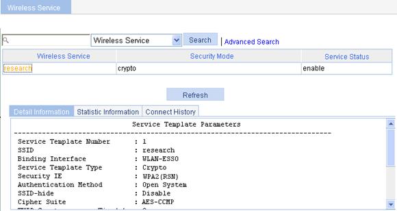
Table 6 Field description
|
Field |
Description |
|
Service Template Number |
Service template number. |
|
SSID |
SSID for the ESS. |
|
Binding Interface |
Name of the interface bound with the service template. |
|
Service Template Type |
Service template type. |
|
Security IE |
Security IE: WPA or WPA2 (RSN) |
|
Authentication Method |
Authentication method: open system or shared key. |
|
SSID-hide |
· Disable—The SSID is advertised in beacon frames. · Enable—Disables the advertisement of the SSID in beacon frames. |
|
Cipher Suite |
Cipher suite: AES-CCMP, TKIP, WEP40, WEP104, or WEP128. |
|
TKIP Countermeasure Time(s) |
TKIP countermeasure time in seconds. |
|
PTK Life Time(s) |
PTK lifetime in seconds. |
|
GTK Rekey |
GTK rekey configured. |
|
GTK Rekey Method |
GTK rekey method configured: packet based or time based. |
|
GTK Rekey Time(s) |
Time for GTK rekey in seconds. · If Time is selected, the GTK will be refreshed after a specified period of time. · If Packet is selected, the GTK will be refreshed after a specified number of packets are transmitted. |
|
Bridge Mode |
Forwarding mode: · Local forwarding—Uses local forwarding in the service template. · Remote forwarding—Uses AC remote forwarding in the service template. |
|
Service Template Status |
Status of service template: · Enable—Enables WLAN service. · Disable—Disables WLAN service. |
|
Maximum clients per BSS |
Maximum number of associated clients per BSS. |
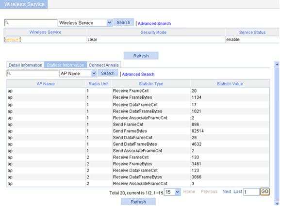
Displaying statistics of WLAN service
The statistics of WLAN service are as shown in Figure 4.
Figure 4 Displaying WLAN service statistics
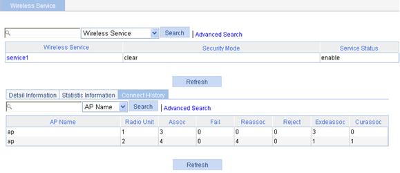
Displaying connection history information of WLAN service
The connection history information of WLAN service is as shown in Figure 5.
Figure 5 Displaying the connection history information of WLAN service
Displaying AP
Select Summary > AP from the navigation tree to enter the AP page, as shown in Figure 6. You can display the WLAN service information, connection history, radio and detailed information of an AP by clicking the tabs on the page.
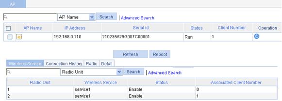
Displaying WLAN service information of an AP
The WLAN service information of an AP is as shown in Figure 6.
Figure 6 Displaying WLAN service information
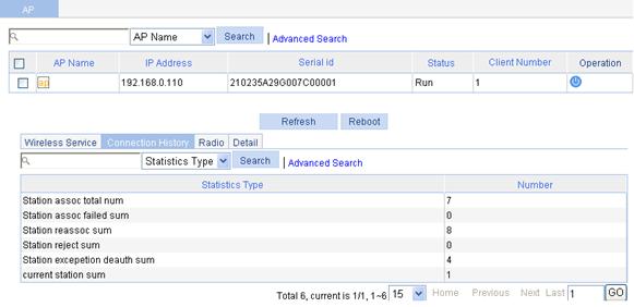
Displaying AP connection history information
The connection history information of an AP is as shown in Figure 7.
Figure 7 Displaying AP connection history information
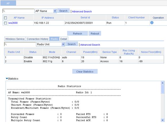
Displaying AP radio information
Select Summary > AP from the navigation tree to enter the AP page, click the Radio tab on the page, and click the name of the specified AP to view the radio statistics of an AP.
The radio statistics of an AP are as shown in Figure 8. For the description of the fields in the AP radio statistics, see Table 7.
Figure 8 Displaying AP radio information
|
|
NOTE: · The Noise Floor item in the table indicates various random electromagnetic waves during the wireless communication. For the environment with a high noise floor, you can improve the signal-to-noise ratio (SNR) by increasing the transmit power or reducing the noise floor. · The Service Type item in the table has two options: Access and Mesh. · Res Using Ratio represents the resource utilization of a radio within a certain period. For example, in a period of 10 seconds, if a radio has occupied the channel for five seconds, the resource utilization of the radio is 5 seconds divided by 10 seconds: 50%. |
|
Field |
Description |
|
AP name |
Access point name. |
|
Radio Id |
Radio ID. |
|
Transmitted Frames Statistics |
Statistics of transmitted frames. |
|
Total Frames |
Total number of frames (probe response frames and beacon frames) transmitted. Total Frames = Unicast Frames + Broadcast/Multicast Frames + Others. |
|
Unicast Frames |
Number of unicast frames (excluding probe response frames) transmitted. |
|
Broadcast/Multicast Frames |
Number of broadcast or multicast frames (excluding beacon frames) transmitted. |
|
Others |
Total number of other type of frames transmitted. |
|
Discard Frames |
Number of frames discarded. |
|
Retry Count |
Number of transmission retries. |
|
Multiple Retry Count |
Number of frames that have been retransmitted. |
|
Authentication Frames |
Number of authentication responses transmitted. |
|
Failed RTS |
Number of RTS failed during transmission. |
|
Successful RTS |
Number of RTS transmitted successfully. |
|
Failed ACK |
Number of transmitted frames for which no acknowledgement is received. |
|
Association Frames |
Number of association responses transmitted. |
|
Received Frames Statistics |
Statistics of received frames. |
|
Total Frames |
Number of frames received. |
|
Unicast Frames |
Number of unicast frames received. |
|
Broadcast/Multicast Frames |
Number of broadcast or multicast frames received. |
|
Fragmented Frames |
Number of fragmented frames received. |
|
FCS Failures |
Number of frames dropped due to FCS failure. |
|
Authentication Frames |
Number of authentication requests received. |
|
Duplicate Frames |
Number of duplicate frames received. |
|
Decryption Errors |
Number of frames dropped due to decryption error. |
|
Association Frames |
Number of association requests received. |
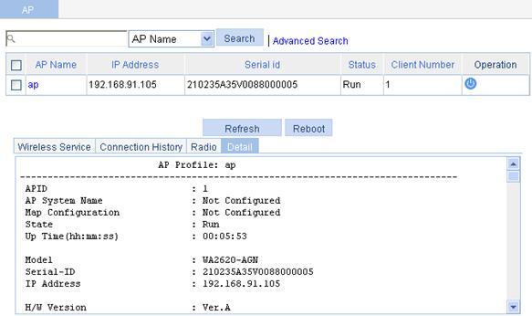
Displaying AP detailed information
Select Summary > AP from the navigation tree to enter the AP page, click the Detail tab on the page, and click the name of the specified AP to view the detailed information of an AP.
The detailed information of an AP is as shown in Figure 9. For the description of the fields in the AP detailed information, see Table 8.
Figure 9 Displaying AP detailed information
|
Field |
Description |
|
APID |
Access point identifier. |
|
AP System Name |
Access point name. |
|
Map Configuration |
Configuration file mapped to the AP. |
|
State |
Current state of the AP: · ImageDownload—The AP is downloading the version. If the ImageDownload state persists, check the following: 1) The version of the fit AP saved on the AC matches with the version that the AC requires; 2) The space of the flash is enough. · Idle—The AP is idle. If the Idle state persists, check the following: 1) If the fields of Latest IP Address and Tunnel Down Reason are displayed as -NA-, it indicates that the AP has never connected to the AC successfully. You need to check the network cable, power supply of the fit AP, and the AP serial number if the serial number was manually input. 2) If the fields of Latest IP Address and Tunnel Down Reason are displayed as other contents, it indicates that the AP has connected to the AC successfully. See the output of the Tunnel Down Reason field for the detailed reason. · Run—The AP is operating. It indicates that the AP has connected to the AC successfully. · Config—The AC is delivering configuration file to the fit AP, and the fit AP is collecting radio information through the radio interface and reporting to the AC. This state is an instantaneous state. |
|
Up Time(hh:mm:ss) |
Time duration for which the AP has been connected to the AC. NA indicates AP is not connected to the AC. |
|
Model |
AP model name. |
|
Serial-ID |
Serial ID of the AP. |
|
IP Address |
IP address of the AP. |
|
H/W Version |
Hardware version of the AP. |
|
S/W Version |
Software version of the AP. |
|
Boot-Rom version |
Boot ROM version of the AP. |
|
Description |
Description of the AP. |
|
Connection Type |
AP connection type: "Master" or "Backup" |
|
Peer AC MAC Address |
Peer AC MAC address in case of AC backup. |
|
Priority Level |
AP connection priority. |
|
Echo Interval(s) |
Interval for sending echo requests, in seconds. |
|
Statistics report Interval(s) |
Interval for sending statistics information messages, in seconds. |
|
Cir (Kbps) |
Committed information rate in kbps. |
|
Cbs (Bytes) |
Committed burst size in bytes. |
|
Jumboframe Threshold |
Threshold value of jumbo frames. |
|
Transmitted control packets |
Number of transmitted control packets. |
|
Received control packets |
Number of received control packets. |
|
Transmitted data packets |
Number of transmitted data packets. |
|
Received data packets |
Number of received data packets. |
|
Configuration Failure Count |
Count of configuration request message failures. |
|
Last Failure Reason |
Last configuration request failure reason. |
|
Last Reboot Reason |
Last reboot reason of the AP: · Normal—The AP was powered off. · Crash—The AP crashed, and the information is needed for analysis. · Tunnel Initiated—The reset wlan ap command is executed on the AC (in this case, the Tunnel Down Reason is displayed as Reset AP). · Tunnel Link Failure—The fit AP rebooted abnormally because an error occurred when the AP was establishing a connection with the AC. |
|
Latest IP Address |
IP address of the last AP. |
|
Tunnel Down Reason |
The tunnel between the AC and the AP is down when one of the following occurs: · Neighbor Dead Timer Expire—The AC does not receive an Echo request from the AP within three times the handshake interval. · Response Timer Expire—The AC sends a control packet to the AP but does not receive any response within the specified waiting time. · Reset AP—The AP is rebooted by the execution of a command on the AC. · AP Config Change: The corresponding configurations are modified on the AC. · No Reason—Other reasons. |
|
Connection Count |
Connection count between the AP and AC. This field is reset in one of the following situations: · AC is rebooted. · You re-configure an AP template after deleting the old one. If you click Reboot on this page to reboot the AP, the connection count will not be reset. |
|
AP Mode |
Mode supported by the AP. Currently only the split MAC mode is supported. |
|
AP operation mode |
Operation mode of AP. Currently Normal and Monitor modes are supported. |
|
Portal Service |
Whether the portal service is enabled or not. |
|
Device Detection |
Whether device detection is enabled or not. |
|
Maximum Number of Radios |
Maximum number of radios supported by the AP. |
|
Current Number of Radios |
Number of radios in use on the AP. |
|
Client Keep-alive Interval |
Interval to detect clients segregated from the system due to various reasons such as power failure or crash, and disconnect them from the AP. |
|
Client Idle Interval(s) |
If the client is idle for more than the specified interval, that is, if the AP does not receive any data from the client within the specified interval, the client will be removed from the network. |
|
Broadcast-probe Reply Status |
Whether the AP is enabled to respond to broadcast probe requests or not. |
|
Basic BSSID |
MAC address of the AP. |
|
Current BSS Count |
Number of BSSs connected with the AP. |
|
Running Clients Count |
Number of clients currently running. |
|
Wireless Mode |
Wireless mode: 802.11a, 802.11b, or 802.11g. |
|
Client Dot11n-only |
· Enabled—Only 802.11n clients can be associated with the AP. · Disabled—802.11a/b/g/n clients can be associated with the AP. |
|
Channel Band-width |
Channel bandwidth, 20 MHz or 40 MHz. |
|
Secondary channel offset |
Secondary channel information for 802.11n radio mode: · SCA (Second Channel Above)—The AP operates in 40 MHz bandwidth mode, and the secondary channel is above the primary channel. · SCB (Second Channel Below)—The AP operates in 40 MHz bandwidth mode, and the secondary channel is below the primary channel. · SCN—The AP operates in 20 MHz bandwidth mode. |
|
HT protection mode |
802.11n protection modes: · no protection mode(0)—The clients associated with the AP, and the wireless devices within the coverage of the AP operate in 802.11n mode, and all the clients associated with the AP operate in either 40 MHz or 20 MHz mode. · Non-member mode(1)—The clients associated with the AP operate in 802.11n mode, but non-802.11n wireless devices exist within the coverage of the AP. · 20 MHz mode(2)—The radio mode of the AP is 40 MHz. The clients associated with the AP and the wireless devices within the coverage of the AP operate in 802.11n mode, and at least one 802.11n client operating in 20 MHz mode is associated with the radio of the AP. · Non-HT mix mode(3)—All situations except the above three. |
|
Short GI for 20MHz |
Whether the AP supports short GI when it operates in 20 MHz mode. |
|
Short GI for 40MHz |
Whether the AP supports short GI when it operates in 40 MHz mode. |
|
Mandatory MCS Set |
Mandatory MCS for the AP. |
|
Supported MCS Set |
Supported MCS for the AP. |
|
A-MSDU |
Status of the A-MSDU function: enable or disable. |
|
A-MPDU |
Status of the A-MPDU function: enable or disable. |
|
Configured Channel |
Operating channel: · If the channel is manually configured, the configured channel number is displayed. · If the channel is automatically selected, auto(channel) is displayed, where channel is the optimal channel automatically selected by the AC. If the AP operates in 802.11n radio mode and 40 MHz bandwidth mode, this field displays the primary channel. |
|
Configured Power(dBm) |
Transmission power on the radio. · If one-time (transmit power control) is adopted, the configured transmit power is displayed. · If auto TPC is adopted, two values are displayed, with the first being the maximum power, and the second auto (number), where number in the brackets represents the actual power. |
|
Interference (%) |
Interference observed on the operating channel, in percentage. |
|
Channel Load (%) |
Load observed on the operating channel, in percentage. |
|
Utilization (%) |
Utilization rate of the operating channel, in percentage. |
|
Co-channel Neighbor Count |
Number of neighbors found on the operating channel. |
|
Channel Health |
Status of the channel. |
|
Preamble Type |
Type of preamble that the AP can support: short or long. |
|
Radio Policy |
Radio policy used. |
|
Service Template |
Service template number. |
|
SSID |
SSID for the ESS. |
|
Port |
WLAN-DBSS interface associated with the service template. |
|
Mesh Policy |
Mesh policy adopted. |
|
ANI Support |
ANI (Adaptive Noise Immunity) status: enabled or disabled. |
|
11g Protection |
11.g protection status: enable or disable. |
|
Admin State |
Administrative state of the radio. |
|
Physical State |
Physical state of the radio. |
|
Operational Rates (Mbps) |
Operational rates in Mbps. |
|
Radar detected Channels |
Channels on which radar signals are detected. |
Displaying clients
Select Summary > Client from the navigation tree to enter the page as shown in Figure 10. For the description of the fields in the client information, see Table 9.
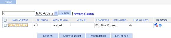
|
Field |
Description |
|
Refresh |
Refresh the current page. |
|
Add to Blacklist |
Add the selected client to the static blacklist, which you can display by selecting Security > Filter from the navigation tree. |
|
Reset Statistic |
Clear statistics of the specified client. |
|
Disconnect |
Log off the selected client. |
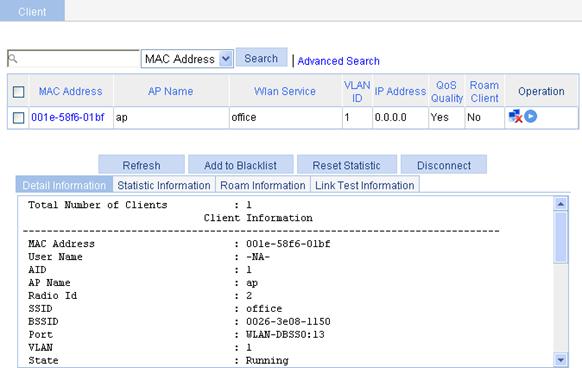
Displaying client detailed information
Select Summary > Client from the navigation tree to enter the Client page, click the Detail Information tab on the page, and click the name of the specified client to view the detailed information of the client.
The detailed information of a client is as shown in Figure 11. For the description of the fields in the client detailed information, see Table 10.
Figure 11 Displaying client detailed information
|
Field |
Description |
|
MAC address |
MAC address of the client. |
|
AID |
Association ID of the client. |
|
User Name |
Username of the client. · The field is displayed as –NA– if the client adopts plain-text authentication or an authentication method that does not require a username. · The field is irrelevant to the portal authentication method. If the client uses the portal authentication method, the field does not display the portal username of the client. |
|
AP Name |
Name of the AP. |
|
Radio Id |
Radio ID of the client. |
|
SSID |
SSID of the AP. |
|
BSSID |
BSSID of the AP. |
|
Port |
WLAN-DBSS interface associated with the client. |
|
VLAN |
VLAN to which the client belongs. |
|
State |
State of the client. Backup indicates a backup client. |
|
Power Save Mode |
Client's power save mode: active or sleep. |
|
Wireless Mode |
Wireless mode such as 802.11a, 802.11b, 802.11g, 802.11an, or 803.11gn. |
|
Channel Band-width |
Channel bandwidth, 20 MHz or 40 MHz. |
|
SM Power Save Enable |
SM Power Save enables a client to have one antenna in active state, and others in sleep state to save power. · Enabled: SM Power Save is supported. · Disabled: SM Power Save is not supported. |
|
Short GI for 20MHz |
Whether the client supports short GI when its channel bandwidth is 20 MHz. · Not Supported. · Supported. |
|
Short GI for 40MHz |
Whether the client supports short GI when its channel bandwidth is 40 MHz. · Not Supported. · Supported. |
|
Support MCS Set |
MCS supported by the client. |
|
BLOCK ACK-TID 0 |
BLOCK ACK is negotiated based on QoS priority ID 0: · OUT—Outbound direction. · IN— Inbound direction. · BOTH—Both directions. |
|
BLOCK ACK-TID 1 |
BLOCK ACK is negotiated based on QoS priority ID 1: · OUT—Outbound direction. · IN—Inbound direction. · BOTH—Both directions. |
|
BLOCK ACK-TID 2 |
BLOCK ACK is negotiated based on QoS priority ID 2: · OUT—Outbound direction. · IN—Inbound direction. · BOTH—Both directions. |
|
BLOCK ACK-TID 3 |
BLOCK ACK is negotiated based on QoS priority ID 3: · OUT—Outbound direction. · IN—Inbound direction. · BOTH—Both directions. |
|
QoS Mode |
Whether the AP supports the WMM function. |
|
Listen Interval (Beacon Interval) |
Specifies how often the client wakes up to receive frames saved in the AP and is expressed in units of beacon interval. |
|
RSSI |
Received signal strength indication. This value indicates the client signal strength detected by the AP. |
|
Rx/Tx Rate |
Represents the frame reception/transmission rate of the client, including data, management, and control frames. For the AC + fit AP mode, there is delay because Rx Rate is transmitted from AP to AC periodically depending on the statistics interval. |
|
Client Type |
Client type such as RSN, WPA, or Pre-RSN. |
|
Authentication Method |
Authentication method such as open system or shared key. |
|
AKM Method |
AKM suite used, such as Dot1X or PSK. |
|
4-Way Handshake State |
Displays either of the 4-way handshake states: · IDLE—Displayed in initial state. · PTKSTART—Displayed when the 4–way handshake is initialized. · PTKNEGOTIATING—Displayed after valid message 3 was sent. · PTKINITDONE—Displayed when the 4-way handshake is successful. |
|
Group Key State |
Displays the group key state: · IDLE—Displayed in initial state. · REKEYNEGOTIATE—Displayed after the AC sends the initial message to the client. · REKEYESTABLISHED—Displayed when re-keying is successful. |
|
Encryption Cipher |
Encryption password: clear or crypto. |
|
Roam Status |
Displays the roaming status: Normal or Fast Roaming. |
|
Roam Count |
Roaming count of the client, including intra-AC roaming and inter-AC roaming. · For intra-AC roaming, this field is reset after the client is de-associated with the AP connected to the AC. · For inter-AC roaming, this field is reset after the client leaves the mobility group to which the AC belongs. |
|
Up Time |
Time for which the client has been associated with the AP. |
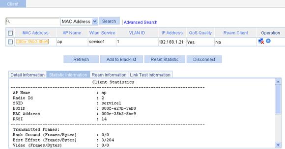
Displaying client statistics
Select Summary > Client from the navigation tree to enter the Client page, click the Statistic Information tab on the page, and click the name of the specified client to view the statistics of the client.
The statistics of a client is as shown in Figure 12. For the description of the fields in the client statistic information, see Table 11.
Figure 12 Displaying client statistics
|
Field |
Description |
|
AP Name |
Name of the associated access point. |
|
Radio Id |
Radio ID. |
|
SSID |
SSID of the AP. |
|
BSSID |
BSSID of the AP. |
|
MAC Address |
MAC Address of the client. |
|
RSSI |
Received signal strength indication. This value indicates the client signal strength detected by the AP. |
|
Transmitted Frames |
Number of transmitted frames. |
|
Back Ground(Frames/Bytes) |
Statistics of background traffic, in frames or in bytes. |
|
Best Effort(Frames/Bytes) |
Statistics of best effort traffic, in frames or in bytes. |
|
Video(Frames/Bytes) |
Statistics of video traffic, in frames or in bytes. |
|
Voice(Frames/Bytes) |
Statistics of voice traffic, in frames or in bytes. |
|
Received Frames |
Number of received frames. |
|
Discarded Frames |
Number of discarded frames. |
|
|
NOTE: You can collect statistics of priority queues such as Back Ground, Best Effort, Video and Voice on a QoS client only. Traffic including SVP packets sent and received on a client where QoS is not enabled falls into Best Effort priority queue. Therefore, the queues collected may be different from the queues actually sent. You can collect statistics of priority queues carried in Dot11E or WMM packets; otherwise, statistics collection of priority queues on the receive end may fail. |
Displaying client roaming information
Select Summary > Client from the navigation tree to enter the Client page, click the Roam Information tab on the page, and click the name of the specified client to view the roaming information of the client.
Client roaming information is as shown in Figure 13. For the detailed description of the fields in the client roaming information, see Table 12.
Figure 13 Displaying client roaming information
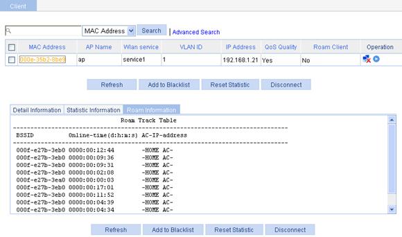
Table 12 Field description
|
Field |
Description |
|
BSSID |
BSSID of the AP associated with the client. |
|
Online-time |
Online time of the client. |
|
AC-IP-address |
The IP address of the AC connected with the client. When the configured roaming channel type is IPv6, the IPv6 address of the AC is displayed. |
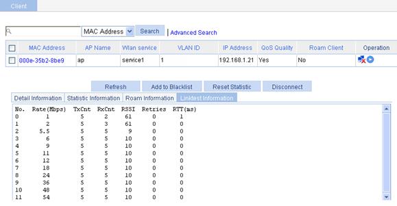
Displaying RF ping information
Radio Frequency Ping (RF Ping) is a ping function performed on wireless links. This function enables you to get the connection information between the AP and its associated clients, such as signal strength, packet re-transmission attempts, and round trip time (RTT).
Select Summary > Client from the navigation tree to enter the Client page, click the Link Test Information tab on the page, and click the name of the specified client to view the link test information of the client, as shown in Figure 14. For the description of the fields in the client link test information, see Table 13.
Figure 14 View link test information
|
Field |
Description |
|
No./MCS |
· Rate number for a non-802.11n client. · MCS value for an 802.11n client. |
|
Rate(Mbps) |
Rate at which the radio interface sends wireless ping frames. |
|
TxCnt |
Number of wireless ping frames that the radio interface sent. |
|
RxCnt |
Number of wireless ping frames that the radio interface received from the client. |
|
RSSI |
Received signal strength indication. This value indicates the client signal strength detected by the AP. |
|
Retries |
Total number of retransmitted ping frames. |
|
RTT(ms) |
Round trip time. |