- Table of Contents
-
- 01-Fundamentals Configuration Guide
- 00-Preface
- 01-CLI configuration
- 02-RBAC configuration
- 03-Login management configuration
- 04-FTP and TFTP configuration
- 05-File system management configuration
- 06-Configuration file management configuration
- 07-Software upgrade configuration
- 08-ISSU configuration
- 09-Emergency shell configuration
- 10-Automatic configuration
- 11-Device management configuration
- 12-Tcl configuration
- 13-License management
- 14-Management with BootWare
- 15-Python configuration
- Related Documents
-
| Title | Size | Download |
|---|---|---|
| 11-Device management configuration | 248.62 KB |
Specifying the system time source
Enabling displaying the copyright statement
Changing the brand name of an MPU
Setting the system operating mode
Rebooting devices immediately at the CLI
Schedule configuration example
Setting the number of redundant power modules
Re-assigning IDs to AC power modules
Setting the fan operating mode
Setting the port status detection timer
Setting memory usage thresholds
Configuring the temperature alarm thresholds
Enabling forwarding acceleration for a card
Configuring hardware failure detection and protection
Specifying the actions to be taken for hardware failures
Enabling hardware failure protection for interfaces
Enabling hardware failure protection for aggregation groups
Enabling data forwarding path failure detection
Verifying and diagnosing transceiver modules
Diagnosing transceiver modules
Disabling alarm traps for transceiver modules
Restoring the factory-default configuration
Displaying and maintaining device management configuration
This chapter describes how to configure basic device parameters and manage the device.
You can perform the configuration tasks in this chapter in any order.
EB cards have the "EB" suffix in their marks, such as LST1GP48LEB1. The similar is true for EC, EF, FC, and FG cards.
Device management task list
|
Tasks at a glance |
|
(Required.) Configuring the device name |
|
(Required.) Configuring the system time |
|
(Optional.) Enabling displaying the copyright statement |
|
(Optional.) Configuring banners |
|
(Optional.) Changing the brand name of an MPU |
|
(Required.) Setting the system operating mode |
|
(Optional.) Rebooting the device |
|
(Optional.) Scheduling a task |
|
(Required.) Managing power supply |
|
(Optional.) Setting the fan operating mode |
|
(Optional.) Setting the port status detection timer |
|
(Optional.) Monitoring CPU usage |
|
(Required.) Setting memory usage thresholds |
|
(Required.) Configuring the temperature alarm thresholds |
|
(Optional.) Disabling all USB interfaces |
|
(Required.) Isolating a card |
|
(Optional.) Enabling forwarding acceleration for a card |
|
(Required.) Configuring hardware failure detection and protection |
|
(Required.) Enabling data forwarding path failure detection |
|
(Optional.) Verifying and diagnosing transceiver modules |
|
(Optional.) Restoring the factory-default configuration |
Configuring the device name
A device name (also called hostname) identifies a device in a network and is used in CLI view prompts. For example, if the device name is Sysname, the user view prompt is <Sysname>.
|
Step |
Command |
Remarks |
|
1. Enter system view. |
system-view |
N/A |
|
2. Configure the device name. |
sysname sysname |
The default device name is H3C. |
Configuring the system time
Correct system time is essential to network management and communication. Configure the system time correctly before you run the device on the network.
Specifying the system time source
The device can use one of the following system time sources:
· None—Local system time. If you specify this time source for the device, you must set the system time as described in "Setting the system time."
· NTP—NTP time source. When the device uses the NTP time source, you cannot change the system time manually. For more information about NTP, see Network Management and Monitoring Configuration Guide.
To specify the system time source:
|
Step |
Command |
Remarks |
|
1. Enter system view. |
system-view |
N/A |
|
2. Specify the system time source. |
clock protocol { none | ntp mdc mdc-id } |
By default, the device uses the NTP time source specified on the default MDC. If you configure this command multiple times, the most recent configuration takes effect. |
Setting the system time
When the system time source is the local system time, the system time is determined by the UTC time, local time zone, and daylight saving time. You can use the display clock command to view the system time.
|
Step |
Command |
Remarks |
|
1. Set the UTC time. |
clock datetime time date |
N/A |
|
2. Enter system view. |
system-view |
N/A |
|
3. Set the local time zone. |
clock timezone zone-name { add | minus } zone-offset |
The default local time zone is the UTC time zone. |
|
4. Set the daylight saving time. |
clock summer-time name start-time start-date end-time end-date add-time |
By default, daylight saving time is disabled. |
Enabling displaying the copyright statement
When displaying the copyright statement is enabled, the device displays the copyright statement in the following situations:
· When a Telnet or SSH user logs in.
· When a console or AUX user quits user view. This is because the device automatically tries to restart the user session again.
The following is a sample copyright statement:
******************************************************************************
* Copyright (c) 2004-2014 Hangzhou H3C Tech. Co., Ltd. All rights reserved. *
* Without the owner's prior written consent, *
* no decompiling or reverse-engineering shall be allowed. *
******************************************************************************
To enable displaying the copyright statement:
|
Step |
Command |
Remarks |
|
1. Enter system view. |
system-view |
N/A |
|
2. Enable displaying the copyright statement. |
copyright-info enable |
By default, this function is enabled. |
Configuring banners
Banners are messages that the system displays when a user logs in.
Banner types
The system supports the following banners:
· Legal banner—Appears after the copyright or license statement. To continue login, the user must enter Y or press Enter. To quit the process, the user must enter N. Y and N are case insensitive.
· Message of the Day (MOTD) banner—Appears after the legal banner and before the login banner.
· Login banner—Appears only when password or scheme authentication is configured.
· Incoming banner.
· Shell banner—Appears for all login users.
Banner input methods
You can configure a single-line banner or a multiline banner.
· Single-line banner.
A single-line banner must be input in the same line as the command. The start and end delimiters for the banner can be any printable character. However, they must be the same and must not be included in the banner. The input text, including the command keywords and the delimiters, cannot exceed 510 characters. Do not press Enter before you input the end delimiter.
For example, you can configure the shell banner "Have a nice day." as follows:
<System> system-view
[System] header shell %Have a nice day.%
· Multiline banner.
A multiline banner can be up to 2000 characters. To input a multiline banner, use one of the following methods:
¡ Method 1—Press Enter after the last command keyword. At the system prompt, enter the banner and end the last line with the delimiter character %. For example, you can configure the banner "Have a nice day. Please input the password." as follows:
<System> system-view
[System] header shell
Please input banner content, and quit with the character '%'.
Have a nice day.
Please input the password.%
¡ Method 2—After you type the last command keyword, type any single printable character as the start delimiter for the banner and press Enter. At the system prompt, type the banner and end the last line with the same delimiter. For example, you can configure the banner "Have a nice day. Please input the password." as follows:
<System> system-view
[System] header shell A
Please input banner content, and quit with the character 'A'.
Have a nice day.
Please input the password.A
¡ Method 3—After you type the last command keyword, type the start delimiter and part of the banner and press Enter. At the system prompt, enter the rest of the banner and end the last line with the same delimiter. For example, you can configure the banner "Have a nice day. Please input the password." as follows:
<System> system-view
[System] header shell AHave a nice day.
Please input banner content, and quit with the character 'A'.
Please input the password.
A
Configuration procedure
To configure banners:
|
Step |
Command |
|
1. Enter system view. |
system-view |
|
2. Configure the legal banner. |
header legal text |
|
3. Configure the MOTD banner. |
header motd text |
|
4. Configure the login banner. |
header login text |
|
5. Configure the incoming banner. |
header incoming text |
|
6. Configure the shell banner. |
header shell text |
Changing the brand name of an MPU
The device supports both H3C MPUs and HP MPUs. H3C recommends that you set the same brand name for the MPUs of the device. The device can operate correctly when it uses one H3C MPU and one HP MPU. However, network management software that identifies a device by the active MPU's brand name cannot identify the device correctly after a switchover. To avoid this problem, use the display brand command to view the brand names of the MPUs and change brand names as required.
To change the brand name of an MPU:
|
Task |
Command |
Remarks |
|
Change the brand name of an MPU. |
· In standalone mode: · In IRF mode: |
The default brand name of an H3C MPU is H3C. The hpn and nec keywords are not supported. Change to the brand name of an MPU takes effect after the MPU reboots. |
Setting the system operating mode
The device can operate in the following modes:
· advance—Advanced mode.
· bridgee—Enhanced Layer 2 mode.
· routee—Enhanced Layer 3 mode.
· standard—Standard mode.
· grand—Grand mode.
In different operating modes, the device supports different features, and might have different specifications for the supported features.
Configuration guidelines
Different cards support different system operating modes, as shown in Table 1.
To achieve the best card performance, set the system operating mode to grand if the device is using only FD cards and FG cards.
Table 1 System operating mode and card compatibility
|
Operating mode |
EB card |
EC card |
EF card |
FD/FG card |
OAA cards |
|
standard |
√ |
√ |
√ |
√ |
√ |
|
bridgee |
× |
√ |
√ |
√ |
√ |
|
routee |
× |
√ |
√ |
√ |
√ |
|
advance |
× |
× |
√ |
√ |
× |
|
grand |
× |
× |
× |
√ |
× |
The √ sign stands for "supported." The × sign stands for "unsupported."
Configuration procedure
To set the system operating mode:
|
Step |
Command |
Remarks |
|
1. Enter system view. |
system-view |
N/A |
|
2. Set the system operating mode. |
system-working-mode { advance | bridgee | routee | standard | grand } |
By default, the device operates in standard mode. |
Rebooting the device
|
|
CAUTION: · A reboot can interrupt network services. · To avoid configuration loss, use the save command to save the running configuration before a reboot. For more information about the save command, see Fundamentals Command Reference. · Before a reboot, use the display startup and display boot-loader commands to verify that the startup configuration file and startup software images are correctly specified. If a startup configuration file or software image problem exists, the device cannot start up correctly. For more information about the two display commands, see Fundamentals Command Reference. |
The following device reboot methods are available:
· Immediately reboot the device at the CLI.
· Schedule a reboot at the CLI, so the device automatically reboots at the specified time or after the specified period of time.
· Power off and then power on the device. This method might cause data loss, and is the least-preferred method.
Using the CLI, you can reboot the device from a remote host.
Configuration guidelines
Follow these guidelines when you schedule a reboot:
· In standalone mode, the automatic reboot configuration is canceled if an active/standby switchover occurs.
· In IRF mode, the automatic reboot configuration is effective on all member devices. It will be canceled if a switchover between the global active MPU and a global standby MPU occurs.
· For data security, the device does not reboot while it is performing file operations.
Rebooting devices immediately at the CLI
Execute one of the following commands as appropriate in user view:
|
Task |
Command |
|
Reboot a card or the entire device. |
· In standalone mode: · In IRF mode: |
Scheduling a device reboot
The device supports only one device reboot schedule. If you configure the scheduler reboot delay or scheduler reboot at command multiple times or configure both commands, the most recent configuration takes effect.
To schedule a reboot, execute either of the following commands in user view:
|
Task |
Command |
Remarks |
|
Specify the reboot date and time. |
scheduler reboot at time [ date ] |
By default, no reboot date or time is specified. |
|
Specify the reboot delay time. |
scheduler reboot delay time |
By default, no reboot delay time is specified. |
Scheduling a task
You can schedule the device to automatically execute a command or a set of commands without administrative interference.
You can configure a one-time schedule or a periodic schedule. A one-time schedule is not saved to the configuration file and is lost when the device reboots. A periodic schedule is saved to the startup configuration file and is automatically executed periodically.
Configuration guidelines
Follow these guidelines when you schedule a task:
· Make sure all commands in a schedule are compliant to the command syntax. The system does not check the syntax when you assign a command to a job.
· A schedule cannot contain any of these commands: telnet, ftp, ssh2, and monitor process.
· A schedule does not support user interaction. If a command requires a yes or no answer, the system always assumes that a Y or Yes is entered. If a command requires a character string input, the system assumes that the either default character string (if any) is entered, or a null string is entered.
· A schedule is executed in the background, and no output (except for logs, traps, and debug information) is displayed for the schedule.
Configuration procedure
To configure a one-time schedule for the device:
|
Step |
Command |
Remarks |
|
1. Enter system view. |
system-view |
N/A |
|
2. Create a job. |
scheduler job job-name |
By default, no job exists. |
|
3. Assign a command to the job. |
command id command |
By default, no command is assigned to a job. You can assign multiple commands to a job. A command with a smaller ID will be executed first. |
|
4. Create a schedule. |
scheduler schedule schedule-name |
By default, no schedule exists. |
|
5. Assign a job to a schedule. |
job job-name |
By default, no job is assigned to a schedule. You can assign multiple jobs to a schedule. The jobs will be executed concurrently. |
|
6. Specify an execution time table for the one-time schedule. |
· Specify the
execution date and time: · Specify the
execution days and time: · Specify the
execution delay time: |
Configure one command as required. By default, no execution time is specified for a schedule. Executing commands clock datetime, clock summer-time, and clock timezone does not change the execution time table that is already configured for a schedule. |
To configure a periodic schedule for the device:
|
Step |
Command |
Remarks |
|
1. Enter system view. |
system-view |
N/A |
|
2. Create a job. |
scheduler job job-name |
By default, no job exists. |
|
3. Assign a command to the job. |
command id command |
By default, no command is assigned to a job. You can assign multiple commands to a job. A job with a smaller ID will be executed first. |
|
4. Create a schedule. |
scheduler schedule schedule-name |
By default, no schedule exists. |
|
5. Assign a job to a schedule. |
job job-name |
By default, no job is assigned to a schedule. You can assign multiple jobs to a schedule. The jobs will be executed concurrently. |
|
6. Specify an execution time table for the periodic schedule. |
· Execute the schedule at an interval from the specified time on: · Execute the schedule at the specified time on every specified day in a month
or week: |
Configure either command. By default, no execution time is specified for a schedule. Executing commands clock datetime, clock summer-time, and clock timezone does not change the execution time table that is already configured for a schedule. |
Schedule configuration example
Network requirements
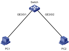
As shown in Figure 1, two interfaces of the device are connected to users.
To save energy, configure the device to perform the following operations:
· Enable interfaces GigabitEthernet 3/0/1 and GigabitEthernet 3/0/2 at 8:00 a.m. every Monday through Friday.
· Disable the interfaces at 18:00 every Monday through Friday.
Scheduling procedure
# Enter system view.
<Sysname> system-view
# Configure a job for disabling interface GigabitEthernet 3/0/1.
[Sysname] scheduler job shutdown-GigabitEthernet3/0/1
[Sysname-job-shutdown-GigabitEthernet3/0/1] command 1 system-view
[Sysname-job-shutdown-GigabitEthernet3/0/1] command 2 interface GigabitEthernet 3/0/1
[Sysname-job-shutdown-GigabitEthernet3/0/1] command 3 shutdown
[Sysname-job-shutdown-GigabitEthernet3/0/1] quit
# Configure a job for enabling interface GigabitEthernet 3/0/1.
[Sysname] scheduler job start-GigabitEthernet3/0/1
[Sysname-job-start-GigabitEthernet3/0/1] command 1 system-view
[Sysname-job-start-GigabitEthernet3/0/1] command 2 interface GigabitEthernet 3/0/1
[Sysname-job-start-GigabitEthernet3/0/1] command 3 undo shutdown
[Sysname-job-start-GigabitEthernet3/0/1] quit
# Configure a job for disabling interface GigabitEthernet 3/0/2.
[Sysname] scheduler job shutdown-GigabitEthernet3/0/2
[Sysname-job-shutdown-GigabitEthernet3/0/2] command 1 system-view
[Sysname-job-shutdown-GigabitEthernet3/0/2] command 2 interface GigabitEthernet 3/0/2
[Sysname-job-shutdown-GigabitEthernet3/0/2] command 3 shutdown
[Sysname-job-shutdown-GigabitEthernet3/0/2] quit
# Configure a job for enabling interface GigabitEthernet 3/0/2.
[Sysname] scheduler job start-GigabitEthernet3/0/2
[Sysname-job-start-GigabitEthernet3/0/2] command 1 system-view
[Sysname-job-start-GigabitEthernet3/0/2] command 2 interface GigabitEthernet 3/0/2
[Sysname-job-start-GigabitEthernet3/0/2] command 3 undo shutdown
[Sysname-job-start-GigabitEthernet3/0/2] quit
# Configure a periodic schedule for enabling the interfaces at 8:00 a.m. every Monday through Friday.
[Sysname] scheduler schedule START-pc1/pc2
[Sysname-schedule-START-pc1/pc2] job start-GigabitEthernet3/0/1
[Sysname-schedule-START-pc1/pc2] job start-GigabitEthernet3/0/2
[Sysname-schedule-START-pc1/pc2] time repeating at 8:00 week-day mon tue wed thu fri
[Sysname-schedule-START-pc1/pc2] quit
# Configure a periodic schedule for disabling the interfaces at 18:00 every Monday through Friday.
[Sysname] scheduler schedule STOP-pc1/pc2
[Sysname-schedule- STOP-pc1/pc2] job shutdown-GigabitEthernet3/0/1
[Sysname-schedule- STOP-pc1/pc2] job shutdown-GigabitEthernet3/0/2
[Sysname-schedule-STOP-pc1/pc2] time repeating at 18:00 week-day mon tue wed thu fri
[Sysname-schedule-STOP-pc1/pc2] quit
Verifying the scheduling
# Display the configuration information of all jobs.
[Sysname] display scheduler job
Job name: shutdown-GigabitEthernet3/0/1
system-view
interface GigabitEthernet 3/0/1
shutdown
Job name: shutdown-GigabitEthernet3/0/2
system-view
interface GigabitEthernet 3/0/2
shutdown
Job name: start-GigabitEthernet3/0/1
system-view
interface GigabitEthernet 3/0/1
undo shutdown
Job name: start-GigabitEthernet3/0/2
system-view
interface GigabitEthernet 3/0/2
undo shutdown
# Display the schedule information.
[Sysname] display scheduler schedule
Schedule name : START-pc1/pc2
Schedule type : Run on every Mon Tue Wed Thu Fri at 08:00:00
Start time : Wed Sep 28 08:00:00 2011
Last execution time : Wed Sep 28 08:00:00 2011
Last completion time : Wed Sep 28 08:00:03 2011
Execution counts : 1
-----------------------------------------------------------------------
Job name Last execution status
start-GigabitEthernet3/0/1 Successful
start-GigabitEthernet3/0/2 Successful
Schedule name : STOP-pc1/pc2
Schedule type : Run on every Mon Tue Wed Thu Fri at 18:00:00
Start time : Wed Sep 28 18:00:00 2011
Last execution time : Wed Sep 28 18:00:00 2011
Last completion time : Wed Sep 28 18:00:01 2011
Execution counts : 1
-----------------------------------------------------------------------
Job name Last execution status
shutdown-GigabitEthernet3/0/1 Successful
shutdown-GigabitEthernet3/0/2 Successful
# Display schedule log information.
[Sysname] display scheduler logfile
Job name : start-GigabitEthernet3/0/1
Schedule name : START-pc1/pc2
Execution time : Wed Sep 28 08:00:00 2011
Completion time : Wed Sep 28 08:00:02 2011
--------------------------------- Job output -----------------------------------
<Sysname>system-view
System View: return to User View with Ctrl+Z.
[Sysname]interface GigabitEthernet 3/0/1
[Sysname-GigabitEthernet3/0/1]undo shutdown
Job name : start-GigabitEthernet3/0/2
Schedule name : START-pc1/pc2
Execution time : Wed Sep 28 08:00:00 2011
Completion time : Wed Sep 28 08:00:02 2011
--------------------------------- Job output -----------------------------------
<Sysname>system-view
System View: return to User View with Ctrl+Z.
[Sysname]interface GigabitEthernet 3/0/2.
[Sysname-GigabitEthernet3/0/2]undo shutdown
Job name : shutdown-GigabitEthernet3/0/1
Schedule name : STOP-pc1/pc2
Execution time : Wed Sep 28 18:00:00 2011
Completion time : Wed Sep 28 18:00:01 2011
--------------------------------- Job output -----------------------------------
<Sysname>system-view
System View: return to User View with Ctrl+Z.
[Sysname]interface GigabitEthernet 3/0/1
[Sysname-GigabitEthernet3/0/1]shutdown
Job name : shutdown-GigabitEthernet3/0/2
Schedule name : STOP-pc1/pc2
Execution time : Wed Sep 28 18:00:00 2011
Completion time : Wed Sep 28 18:00:01 2011
--------------------------------- Job output -----------------------------------
<Sysname>system-view
System View: return to User View with Ctrl+Z.
[Sysname]interface GigabitEthernet 3/0/2
[Sysname-GigabitEthernet3/0/2]shutdown
Managing power supply
Power modules might have problems such as overloading, overcurrent, overvoltage, overtemperature, and short circuit. Some power modules use a hardware protection measure, for example, powering off the device, to protect the entire device from being damaged. The hardware protection measure helps protect the device but interrupts services. The power supply management feature can minimize service interruption while protecting the device against overloading problems.
The power supply management feature constantly monitors the amount of usable power and the system loads. If a potential power supply problem is found, this feature takes protective measures immediately to remove requirements for power supply hardware protection. Examples of protective measures include sending a notification, starting to use the redundant power, and powering off certain LPUs.
|
|
IMPORTANT: To make sure the power modules and the device can operate correctly, do not install AC and DC power modules on the same device. |
Setting the number of redundant power modules
All power modules on the device operate in load balanced mode. By setting the number of redundant power modules, you specify the expected redundant power. For example, the remaining power is greater than 6000 W and the rated power is 2000 W. If you set the number of redundant power modules to 3, you expect 6000 W of redundant power.
Setting the number of redundant power modules does not affect power allocation. When the usable power cannot meet the system power requirement, the device uses the redundant power if power supply management is enabled and the number of redundant power modules is set.
You can use the display power-supply verbose command to monitor the actual redundant power. If the actual redundant power is less than the expected redundant power, you can add power modules to ensure robust system power supply.
Output of the display power-supply verbose command includes the following fields:
· System power-module redundant(configured)—Number of redundant power modules.
· System power redundant(actual)—Actual redundant power. This value is always a multiple of the rated power.
¡ If Remaining power ≥ Rated power × Number of redundant power modules, Actual redundant power = Rated power x Number of redundant power modules.
¡ If Remaining power < Rated power × Number of redundant power modules, Actual redundant power = | Remaining power/Rated power | × Rated power.
For example, Rated power = 2000 W, and Number of redundant power modules = 3.
If Remaining power < 2000 W, Actual redundant power = 0 W.
If 2000 W ≤ Remaining power < 3000 W, Actual redundant power = 2000 W.
The following formulas show the relationships of the main power parameters:
· Remaining power = Total power – Allocated power
· Total power = Rated power × Number of power modules
· Allocated power = Total power used by hardware modules (including cards and fans)
· Usable power = Rated power × Number of power modules – Actual redundant power
For power consumption information about hardware modules, see the installation guide.
To set the number of redundant power modules in standalone mode:
|
Step |
Command |
Remarks |
|
1. Enter system view. |
system-view |
N/A |
|
2. Enable power supply management. |
power-supply policy enable |
By default, power supply management is enabled. |
|
3. Specify the number of redundant power modules. |
power-supply policy redundant module-count |
By default, the number of redundant power modules is 1. The configuration of this command takes effect only when power supply management is enabled. |
|
4. Display redundant power information. |
display power-supply verbose |
N/A |
To set the number of redundant power modules in IRF mode:
|
Step |
Command |
Remarks |
|
1. Enter system view. |
system-view |
N/A |
|
2. Enable power supply management. |
power-supply policy chassis chassis-number enable |
By default, power supply management is enabled. |
|
3. Specify the number of redundant power modules. |
power-supply policy chassis chassis-number redundant module-count |
By default, the number of redundant power modules is 1. The configuration of this command takes effect only when power supply management is enabled. |
|
4. Display redundant power information. |
display power-supply verbose |
N/A |
Powering on/off a card
You can manually power on or off cards to adjust the available power. The power supply status can be displayed with the display power-supply command.
To power on or off a card in standalone mode, execute one of the following commands in user view:
|
Task |
Command |
|
Power on a card. |
power-supply on slot slot-number |
|
Power off a card. |
power-supply off slot slot-number |
To power on or off a card in IRF mode, execute one of the following commands in user view:
|
Task |
Command |
Remarks |
|
Power on a card. |
power-supply on chassis chassis-number slot slot-number |
N/A |
|
Power off a card. |
power-supply off chassis chassis-number slot slot-number |
To avoid IRF split, the system does not power off an LPU that contains all active physical IRF ports of a member device. |
Re-assigning IDs to AC power modules
This feature applies only to PSE9000 AC power modules.
Power modules need IDs for easy identification. For PSE9000-A and PSE9000-D AC power modules, the system automatically uses the slot numbers of the modules as the IDs, as shown in Figure 2 and Figure 3. For PSE9000 AC power modules, however, the system randomly assigns IDs at startup. These randomly assigned IDs have no relationship with the power modules' slot numbers. You can re-assign IDs to PSE9000 AC power modules after you install the device. For easy identification, H3C recommends that you use the slot numbers as the power module IDs.
Figure 2 Slot numbers of AC power modules in an S12508 switch
![]()
Figure 3 Slot numbers of AC power modules in an S12518 switch
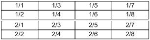
Figure 4 Slot numbers of AC power modules in an S12504 switch
![]()
To help you correlate the current IDs of AC power modules with their slot numbers, the switch provides the power-supply led-blink command. After you execute this command for a power module, the operation LED of the power module blinks to show you its location. If you execute this command without specifying a power module ID, all power modules blink one by one in ascending order of IDs.
Configuration guidelines
Each AC power module must have a unique ID.
To view the models and IDs of power modules, use the display power-supply command.
If the switch reboots after AC power modules get IDs, the IDs of the power modules might change.
· If no power module changes occur or only some power modules are removed since the last ID change, the IDs of the power modules remain the same.
· If some power modules have been added or re-located since the last ID change, the switch randomly re-assigns IDs to the power modules.
|
|
IMPORTANT: To hot-swap AC power modules, follow these guidelines: · After you insert one AC power module in to the power frame, wait a minimum of three seconds before inserting another one. · After you remove one AC power module from the power frame, wait a minimum of 15 seconds before inserting or removing another one. Failure to follow these guidelines might cause multiple power modules to use the same ID. |
Configuration procedure
To re-assign IDs to AC power modules:
|
Step |
Command |
Remarks |
|
1. Enter system view. |
system-view |
N/A |
|
2. (Optional.) Correlate IDs randomly assigned by the system with the slot numbers of power modules. |
· In standalone mode: · In IRF mode: |
By default, the operation LED blink duration of an AC power module is 3 seconds and the delay time is 0 seconds. |
|
3. Re-assign IDs to AC power modules. |
· In standalone mode: · In IRF mode: |
By default, the power modules use the IDs randomly assigned by the system. |
Configuration example
Figure 5 Intended IDs for the power modules
![]()
To re-assign IDs to the three PSE9000 AC power modules as shown in Figure 5:
1. Correlate the randomly assigned IDs with the slot numbers of power modules.
<Sysname> system-view
[Sysname] power-supply led-blink module 1 blink-time 5 delay-time 10
[Sysname] power-supply led-blink module 2 blink-time 5 delay-time 10
[Sysname] power-supply led-blink module 3 blink-time 5 delay-time 10
Observe the operation LEDs of the power modules after executing each power-supply led-blink command. Suppose the result is as shown in Figure 6.
Figure 6 Randomly assigned IDs of the power modules
![]()
2. Re-assign IDs.
<Sysname> system-view
[Sysname] power-supply module 3 1 2 new-id 1 3 5
Setting the fan operating mode
Fans can operate in one of the following modes:
· Low-temperature mode—Operate at a higher speed to provide better cooling service.
· Silence mode—Operate at a lower speed to reduce the noise at the cost of lower cooling service quality. This mode applies to noise-sensitive environments.
To set the fan operating mode:
|
Step |
Command |
Remarks |
|
1. Enter system view. |
system-view |
N/A |
|
2. Set the fan operating mode. |
· In standalone mode: · In IRF mode: |
By default, fans operate in low-temperature mode. |
Setting the port status detection timer
To set the port status detection timer:
|
Step |
Command |
Remarks |
|
1. Enter system view. |
system-view |
N/A |
|
2. Set the port status detection timer. |
shutdown-interval time |
The default setting is 30 seconds. |
Monitoring CPU usage
You can enable CPU usage monitoring so the system periodically samples and saves CPU usage. To view the recent CPU usage, use the display cpu-usage history command.
To monitor CPU usage in standalone mode:
|
Command |
Remarks |
|
|
1. Enter system view. |
N/A |
|
|
2. Enable CPU usage monitoring. |
monitor cpu-usage enable [ slot slot-number] |
By default, CPU usage monitoring is enabled. |
|
3. Set the CPU usage sampling interval. |
monitor cpu-usage interval interval-value [ slot slot-number] |
By default, the CPU usage sampling interval is 1 minute. |
|
4. Exit to user view. |
N/A |
|
|
5. Display CPU usage statistics. |
display cpu-usage [ slot slot-number [ cpu cpu-number ] ] |
This command is available in any view. |
|
6. Display CPU usage monitoring settings. |
display cpu-usage configuration [ slot slot-number [ cpu cpu-number ] ] |
This command is available in any view. |
|
7. Display the historical CPU usage statistics in a coordinate system. |
display cpu-usage history [ job job-id ] [ slot slot-number [ cpu cpu-number ] ] |
This command is available in any view. |
To monitor CPU usage in IRF mode:
|
Command |
Remarks |
|
|
1. Enter system view. |
N/A |
|
|
2. Enable CPU usage monitoring. |
monitor cpu-usage enable [ chassis chassis-number slot slot-number ] |
By default, CPU usage monitoring is enabled. |
|
3. Set the CPU usage sampling interval. |
monitor cpu-usage interval interval-value [ chassis chassis-number slot slot-number ] |
By default, the CPU usage sampling interval is 1 minute. |
|
4. Exit to user view. |
N/A |
|
|
5. Display CPU usage statistics. |
display cpu-usage [ chassis chassis-number slot slot-number [ cpu cpu-number ] ] |
This command is available in any view. |
|
6. Display CPU usage monitoring settings. |
display cpu-usage configuration [ chassis chassis-number slot slot-number [ cpu cpu-number ] ] |
This command is available in any view. |
|
7. Display the historical CPU usage statistics in a coordinate system. |
display cpu-usage history [ job job-id ] [ chassis chassis-number slot slot-number [ cpu cpu-number ] ] |
This command is available in any view. |
Setting memory usage thresholds
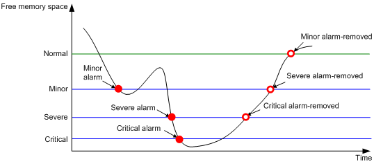
To ensure correct operation and improve memory efficiency, the system monitors the amount of free memory space in real time. When a threshold is exceeded, the system generates an alarm notification or an alarm-removed notification and sends it to affected service modules or processes.
As shown in Table 2 and Figure 7, the system supports the following thresholds:
· Normal state threshold.
· Minor alarm threshold.
· Severe alarm threshold.
· Critical alarm threshold.
Table 2 Memory alarm notifications and memory alarm-removed notifications
|
Notification |
Triggering condition |
Remarks |
|
Minor alarm notification |
The amount of free memory space decreases to or below the minor alarm threshold for the first time. |
After generating and sending a minor alarm notification, the system does not generate and send any additional minor alarm notifications until the first minor alarm is removed. |
|
Severe alarm notification |
The amount of free memory space decreases to or below the severe alarm threshold for the first time. |
After generating and sending a severe alarm notification, the system does not generate and send any additional severe alarm notifications until the first severe alarm is removed. |
|
Critical alarm notification |
The amount of free memory space decreases to or below the critical alarm threshold for the first time. |
After generating and sending a critical alarm notification, the system does not generate and send any additional critical alarm notifications until the first critical alarm is removed. |
|
Critical alarm-removed notification |
The amount of free memory space increases to or above the severe alarm threshold. |
N/A |
|
Severe alarm-removed notification |
The amount of free memory space increases to or above the minor alarm threshold. |
N/A |
|
Minor alarm-removed notification |
The amount of free memory space increases to or above the normal state threshold. |
N/A |
Figure 7 Memory alarm notification and alarm-removed notification
To set memory usage thresholds:
|
Step |
Command |
Remarks |
|
1. Enter system view. |
system-view |
N/A |
|
2. Set memory usage thresholds. |
· In standalone mode: · In IRF mode: |
The defaults are as follows: · Minor alarm threshold—96 MB. · Severe alarm threshold—64 MB. · Critical alarm threshold—48 MB. · Normal state threshold—128 MB. |
Configuring the temperature alarm thresholds
The device monitors its temperature based on the following thresholds:
· Low-temperature threshold.
· High-temperature warning threshold.
· High-temperature alarming threshold.
When the temperature drops below the low-temperature threshold or reaches the high-temperature warning threshold, the device performs the following tasks:
· Logs the event.
· Sends a log message.
· Sends a trap.
When the temperature reaches the high-temperature alarming threshold, the device performs the following tasks:
· Logs the event.
· Sends log messages repeatedly.
· Sends traps repeatedly.
· Sets the LEDs on the device panel.
To configure the temperature alarm thresholds:
Disabling all USB interfaces
This feature is supported only on the default MDC.
You can use USB interfaces to transfer files. By default, all USB interfaces are enabled. You can disable USB interfaces as needed.
To disable all USB interfaces:
|
Step |
Command |
Remarks |
|
1. Enter system view. |
system-view |
N/A |
|
2. Disable all USB interfaces. |
usb disable |
By default, all USB interfaces are enabled. Before using this command, use the umount command to unmount all USB partitions. |
Isolating a card
When a card fails or an LPU's CPU daughter card logic needs to be upgraded, you can isolate the card from the system. The card then stops providing services without affecting system operation and the services on other cards.
An isolated card is in offline state. You can use the display device command to verify the status.
Isolation guidelines
You can isolate only standby MPUs. In IRF mode, you can isolate one standby MPU only when the member device has another MPU operating correctly.
In standalone mode, you cannot isolate a switching fabric module that is the only switching fabric module on the device. In IRF mode, you cannot isolate a switching fabric module that is the only switching fabric module on a member device.
You cannot perform an ISSU when one or more cards are isolated.
Do not perform configurations for an isolated card. The configurations might not be able to take effect.
To eliminate possible impact on the system, H3C recommends that you isolate a switching fabric module before removing it.
Isolation procedure
To isolate a card:
|
Step |
Command |
Remarks |
|
1. Enter system view. |
system-view |
N/A |
|
2. Isolate a card. |
· In standalone mode: · In IRF mode: |
By default, a card is not isolated. |
Enabling forwarding acceleration for a card
Use this task under the guidance of H3C Support. Enabling forwarding acceleration for a card improves the card's forwarding performance, but doing so might overwhelm the switching fabric cards and result in packet loss.
You can enable forwarding acceleration only when the following requirements are met:
· The device model is LS-12508-AC-3, LS-12508-DC-3, LS-12518-AC-3, or LS-12518-DC-3.
· The card is an FD or FG interface card (except for LST1CP4RFD1, LST1CP4RFG1, LST1CP4RFD2, and LST1CP4RFG2).
Forwarding acceleration is enabled on the previously mentioned FD or FG interface cards by default. You cannot disable forwarding acceleration on them.
· The device is not operating in grand mode. For more information about operating modes, see "Setting the system operating mode."
· You are in the system view of the default MDC. For more information about MDC, see Virtual Technologies Configuration Guide.
To enable forwarding acceleration for a card:
|
Step |
Command |
Remarks |
|
1. Enter system view. |
system-view |
N/A |
|
2. Enable forwarding acceleration for a card. |
· In standalone mode: · In IRF mode: |
By default, forwarding acceleration is disabled for cards, except for LST1CP4RFD1, LST1CP4RFG1, LST1CP4RFD2, and LST1CP4RFG2. For this command to take effect, use the reboot command to reboot the device. |
Configuring hardware failure detection and protection
The device can automatically detect hardware failures on components, cards, and the forwarding plane and take actions in response.
Specifying the actions to be taken for hardware failures
The device can take the following actions in response to hardware failures:
· isolate—Performs the following tasks as appropriate to reduce impact from the failures:
¡ Shuts down the relevant ports.
¡ Prohibits loading software for the relevant cards.
¡ Isolates the relevant cards.
¡ Powers off the relevant cards.
· reset—Restarts the relevant components or cards to recover from failures.
· warning—Sends traps to notify you of the failures.
To specify the actions to be taken in response to hardware failures:
|
Step |
Command |
Remarks |
|
1. Enter system view. |
system-view |
N/A |
|
2. Specify the action to be taken in response to a type of hardware failures. |
hardware-failure-detection { board | chip | forwarding } { off | isolate | reset | warning } |
By default, the system takes the action of warning in response to hardware failures. |
Enabling hardware failure protection for interfaces
After you enable hardware failure protection on an interface, the system automatically shuts down the interface when it detects a hardware failure on the interface. An interface shut down this way is in Protect Down state.
Before enabling hardware failure protection on an interface, make sure a backup link is available for uninterrupted services.
After the failure on an interface is removed, bring the interface up using the undo shutdown command.
To enable hardware failure protection for an interface:
|
Step |
Command |
Remarks |
|
1. Enter system view. |
system-view |
N/A |
|
2. Set the action to be taken in response to failures on the forwarding plane to isolate. |
hardware-failure-detection forwarding isolate |
By default, the system takes the action of warning (sending traps) in response to forwarding-plane failures. |
|
3. Enter Ethernet interface view. |
interface interface-type interface-number |
N/A |
|
4. Enable hardware failure protection for the interface. |
hardware-failure-protection auto-down |
By default, hardware failure protection is enabled. |
Enabling hardware failure protection for aggregation groups
After you enable hardware failure protection for aggregation groups, the system follows these rules when it detects a hardware failure on a member interface of an aggregation group:
· If the member interface is not the last member in up state in the group, the system shuts down the interface.
· If the member interface is the last member in up state in the group, the system does not shut down the interface.
Configuration guidelines
The hardware-failure-protection aggregation and hardware-failure-protection auto-down commands do not take effect on an interface in the following situations:
· Loopback testing is enabled (by using the loopback { external | internal } command).
· The interface is forcibly brought up (by using the port up-mode command).
· The interface is a physical IRF port. For more information about physical IRF ports, see Virtual Technologies Configuration Guide.
An interface shut down for hardware failure protection is in Protect DOWN state. You can use the display interface command to view the status. To restore the interface to UP state, execute the undo shutdown command.
For a card that is isolated or forbidden to load software, you can remove it and then reinstall it to restore it to operating state.
To view hardware failure detection and protection information, use the display hardware-failure-detection command.
Configuration procedure
To enable hardware failure protection for aggregation groups:
|
Step |
Command |
Remarks |
|
1. Enter system view. |
system-view |
N/A |
|
2. Set the action to be taken in response to failures on the forwarding plane to isolate. |
hardware-failure-detection forwarding isolate |
By default, the system takes the action of warning (sending traps) in response to forwarding-plane failures. |
|
3. Enter Ethernet interface view. |
interface interface-type interface-number |
N/A |
|
4. Disable hardware failure protection for the interface. |
undo hardware-failure-protection auto-down |
By default, hardware failure protection is enabled. Configure this command on every member interface in the aggregation group. If you do not configure this command on a member device, the system shuts down the interface when it detects a hardware failure on the interface. It does not check whether or not the interface is the last member in up state in the group. |
|
5. Exit to system view. |
quit |
N/A |
|
6. Enable hardware failure protection for aggregation groups. |
hardware-failure-protection aggregation |
By default, hardware failure protection is disabled for aggregation groups. |
Enabling data forwarding path failure detection
You can enable the device to automatically detect data forwarding path failures and output log information for notification.
To enable data forwarding path failure detection:
|
Step |
Command |
Remarks |
|
1. Enter system view. |
system-view |
N/A |
|
2. Enable data forwarding path failure detection. |
forward-path-detection enable |
By default, data forwarding path failure detection is enabled. |
Verifying and diagnosing transceiver modules
Verifying transceiver modules
You can use one of the following methods to verify the genuineness of a transceiver module:
· Display the key parameters of a transceiver module, including its transceiver type, connector type, central wavelength of the transmit laser, transfer distance, and vendor name.
· Display its electronic label. The electronic label is a profile of the transceiver module and contains the permanent configuration, including the serial number, manufacturing date, and vendor name. The data is written to the storage component during debugging or testing.
To verify transceiver modules, execute the following commands in any view:
|
Task |
Command |
Remarks |
|
Display key parameters of transceiver modules. |
display transceiver { interface [ interface-type interface-number ] } |
N/A |
|
Display transceiver modules' electrical label information. |
display transceiver manuinfo interface [ interface-type interface-number ] } |
This command cannot display information for some transceiver modules. |
Diagnosing transceiver modules
The device provides the alarm and digital diagnosis functions for transceiver modules. When a transceiver module fails or is not operating correctly, you can perform the following tasks:
· Check the alarms that exist on the transceiver module to identify the fault source.
· Check the key parameters monitored by the digital diagnosis function, including the temperature, voltage, laser bias current, TX power, and RX power.
To diagnose transceiver modules, execute the following command in any view:
|
Task |
Command |
Remarks |
|
Display transceiver alarms. |
display transceiver alarm { interface [ interface-type interface-number ] } |
N/A |
|
Display the current values of the digital diagnosis parameters on transceiver modules. |
display transceiver diagnosis { interface [ interface-type interface-number ] } |
This command cannot display information about some transceiver modules. |
Disabling alarm traps for transceiver modules
Disable alarm traps for transceiver modules that were manufactured or sold by H3C.
The device regularly detects transceiver modules that have no vendor name or have a vendor name other than H3C. Upon detecting such a transceiver module, the device repeatedly outputs traps and logs to notify the user to replace the module.
To disable alarm traps for transceiver modules:
|
Step |
Command |
Remarks |
|
1. Enter system view. |
system-view |
N/A |
|
2. Disable alarm traps for transceiver modules. |
transceiver phony-alarm-disable |
By default, alarm traps are enabled for transceiver modules. |
Restoring the factory-default configuration
|
|
CAUTION: This task is disruptive. Use this task only when you cannot troubleshoot the device by using other methods, or you want to use the device in a different scenario. |
This feature performs the following tasks:
· Deletes all configuration files (.cfg files) in the root directories of the storage media.
· Deletes all log files (.log files in the folder /logfile).
· Clears all log information (in the log buffer), trap information, and debugging information.
· Restores the parameters for the BootWare to the factory-default settings.
· Deletes all license files (.ak files).
After this command is executed, only items required for fundamental device operation are retained. These items include the .bin files, the MAC addresses, and the electronic label information.
To restore the factory-default configuration for the device, execute the following command in user view:
|
Command |
Remarks |
|
|
Restore the factory-default configuration for the device. |
This command takes effect after a device reboot. |
Displaying and maintaining device management configuration
Execute display commands in any view and reset commands in user view.
In standalone mode:
|
Task |
Command |
|
Display device alarm information. |
display alarm [ slot slot-number ] |
|
Display the brand information of MPUs. |
display brand |
|
Display the system time, date, local time zone, and daylight saving time. |
display clock |
|
Display the copyright statement. |
display copyright |
|
Display hardware information. |
display device [ cf-card | flash ] [ slot slot-number | verbose ] |
|
Display the electronic label information of the device. |
display device manuinfo [ slot slot-number ] |
|
Display the electronic label information of the specified chassis backplane. (In standalone mode.) |
display device manuinfo chassis-only |
|
Display the electronic label information of a fan. |
display device manuinfo fan fan-id |
|
Display the electronic label information of a power module. |
display device manuinfo power power-id |
|
Display the electronic label data of a power monitoring unit. |
display device manuinfo power-monitor pmu-id |
|
Display the operating statistics for multiple feature modules. |
display diagnostic-information [ hardware | infrastructure | l2 | l3 | service ] |
|
Display device temperature statistics. |
display environment [ slot slot-number ] |
|
Display the switching fabric channel usage. |
display fabric utilization [ slot slot-number ] |
|
Display the operating states of fans. |
display fan [ verbose ] |
|
Display the current fan operating mode. |
display fan auto-control-mode |
|
Display hardware failure detection and fix information. |
display hardware-failure-detection |
|
Display hardware failure protection information. |
display hardware-failure-protection [ aggregation | port { auto-down | interface-type interface-number } ] |
|
Display memory usage statistics. |
display memory [ slot slot-number [ cpu cpu-number ] ] |
|
Display memory usage thresholds. |
display memory-threshold [ slot slot-number ] |
|
Display power supply information. |
display power-supply [ verbose ] |
|
Display job configuration information. |
display scheduler job [ job-name ] |
|
Display job execution log information. |
display scheduler logfile |
|
Display the automatic reboot schedule. |
display scheduler reboot |
|
Display schedule information. |
display scheduler schedule [ schedule-name ] |
|
Display the current system operating mode. |
display system-working-mode |
|
Display transceiver alarms. |
display transceiver alarm interface [ interface-type interface-number ] |
|
Display the current values of the digital diagnosis parameters on transceiver modules. |
display transceiver diagnosis interface [ interface-type interface-number ] |
|
Display the key parameters of transceiver modules. |
display transceiver interface [ interface-type interface-number ] |
|
Display the electronic label information of transceiver modules. |
display transceiver manuinfo interface [ interface-type interface-number ] |
|
Display system version information. |
display version |
|
Clear job execution log information. |
reset scheduler logfile |
In IRF mode:
|
Task |
Command |
|
Display device alarm information. |
display alarm [ chassis chassis-number slot slot-number ] |
|
Display the brand information of MPUs. |
display brand |
|
Display the system time ,date, local time zone, and daylight saving time. |
display clock |
|
Display the copyright statement. |
display copyright |
|
Display hardware information. |
display device [ cf-card | flash ] [ chassis chassis-number [ slot slot-number ] | verbose ] |
|
Display the electronic label information of the device. |
display device manuinfo [ chassis chassis-number [ slot slot-number ] ] |
|
Display the electronic label information of the specified chassis backplane. |
display device manuinfo chassis chassis-number chassis-only |
|
Display the electronic label information of a fan. |
display device manuinfo chassis chassis-number fan fan-id |
|
Display the electronic label information of a power module. |
display device manuinfo chassis chassis-number power power-id |
|
Display the electronic label data of a power monitoring unit. |
display device manuinfo chassis chassis-number power-monitor pmu-id |
|
Display the operating statistics for multiple feature modules. |
display diagnostic-information [ hardware | infrastructure | l2 | l3 | service ] |
|
Display device temperature statistics. |
display environment [ chassis chassis-number [ slot slot-number ] ] |
|
Display the switching fabric channel usage. |
display fabric utilization [ chassis chassis-number slot slot-number ] |
|
Display the operating states of fans. |
display fan [ chassis chassis-number ] [ verbose ] |
|
Display the current fan operating mode. |
display fan auto-control-mode chassis chassis-number |
|
Display hardware failure protection information. |
display hardware-failure-protection [ aggregation | port { auto-down | interface-type interface-number } ] |
|
Display memory usage statistics. |
display memory [ chassis chassis-number slot slot-number [ cpu cpu-number ] ] |
|
Display memory usage thresholds. |
display memory-threshold [ chassis chassis-number slot slot-number ] |
|
Display power supply information. |
display power-supply [ chassis chassis-number ] [ verbose ] |
|
Display job configuration information. |
display scheduler job [ job-name ] |
|
Display job execution log information. |
display scheduler logfile |
|
Display the automatic reboot schedule. |
display scheduler reboot |
|
Display schedule information. |
display scheduler schedule [ schedule-name ] |
|
Display the current system operating mode. |
display system-working-mode |
|
Display transceiver alarms. |
display transceiver alarm interface [ interface-type interface-number ] |
|
Display the current values of the digital diagnosis parameters on transceiver modules. |
display transceiver diagnosis interface [ interface-type interface-number ] |
|
Display the key parameters of transceiver modules. |
display transceiver interface [ interface-type interface-number ] |
|
Display the electronic label information of transceiver modules. |
display transceiver manuinfo interface [ interface-type interface-number ] |
|
Display system version information. |
display version |
|
Clear job execution log information. |
reset scheduler logfile |