- Table of Contents
-
- 01-Fundamentals Configuration Guide
- 00-Preface
- 01-CLI configuration
- 02-RBAC configuration
- 03-Login management configuration
- 04-FTP and TFTP configuration
- 05-File system management configuration
- 06-Configuration file management configuration
- 07-Software upgrade configuration
- 08-ISSU configuration
- 09-Emergency shell configuration
- 10-Automatic configuration
- 11-Device management configuration
- 12-Tcl configuration
- 13-License management
- 14-Management with BootWare
- 15-Python configuration
- Related Documents
-
| Title | Size | Download |
|---|---|---|
| 07-Software upgrade configuration | 176.79 KB |
Contents
Software file naming conventions
Comware image redundancy and loading procedure
Non-ISSU upgrade procedure summary
Preloading the BootWare image to BootWare
Specifying the startup image file and completing the upgrade (in standalone mode)
Specifying the startup image file and completing the upgrade (in IRF mode)
Upgrading MBUS daughter card software
Upgrading or repairing the power software on an interface card
Upgrading the power monitor software
Upgrading fan monitor software
Enabling software synchronization from the active MPU to the standby MPU at startup
Displaying and maintaining software image settings
Non-ISSU software upgrade example (for standalone mode)
This chapter describes types of software and how to upgrade software from the CLI without using ISSU. For a comparison of all software upgrade methods, see "Upgrade methods."
Overview
Software upgrade enables you to add new features and fix bugs. Before performing an upgrade, use the release notes for the new software version to verify software and hardware compatibility and evaluate upgrade impacts.
Software types
The following software types are available:
· BootWare image—A .bin file that contains a basic segment and an extended segment. The basic segment is the minimum code that bootstraps the system. The extended segment enables hardware initialization and provides system management menus. You can use these menus to load software and the startup configuration file or manage files when the device cannot start up correctly.
· Comware image—Includes the following image subcategories:
¡ Boot image—A .bin file that contains the Linux operating system kernel. It provides process management, memory management, file system management, and the emergency shell.
¡ System image—A .bin file that contains the minimum feature modules required for device operation and some basic features, including device management, interface management, and configuration management. To have advanced features, you must purchase feature images.
¡ Feature image—A .bin file that contains advanced software features. Users purchase feature images as needed.
¡ Patch image—A .bin file irregularly released for fixing bugs without rebooting the device. A patch image does not add new features or functions.
Comware software images that have been loaded are called "current software images." Comware images specified to load at the next startup are called "startup software images."
BootWare image, boot image, and system image are required for the system to work. These images might be released separately or as a whole in one .ipe package file. If an .ipe file is used, the system automatically decompresses the file, loads the .bin boot and system images and sets them as startup software images. Typically, the BootWare and startup software images for the device are released in an .ipe file named main.ipe.
Software file naming conventions
Software image file names use the chassis-comware version-image type-release format, for example, S12500-CMW710-SYSTEM-A732003_mrpnc.bin and S12500-CMW710-BOOT-A732003_mrpnc.bin. This document uses boot.bin and system.bin as boot and system image file names.
Comware image redundancy and loading procedure
You can specify two sets of Comware software images: one main and one backup.
The system always attempts to start up with the main images. If any main image does not exist or is invalid, the system tries the backup images. Figure 1 shows the entire Comware image loading procedure.
This procedure assumes that both the main and backup image sets have feature and patch images. If an image set does not have either feature images or patch images, the system starts up with the main boot and system images after they pass verification.
If both the main and backup boot images do not exist or are invalid, connect to the console port and power cycle the device to load a boot image from the BootWare menu. For more information about downloading and loading a boot image, see the release notes for the software version.
After accessing the emergency shell, connect to the console port and load a system image so you can access the Comware system. For more information about using the emergency shell, see "Using the emergency shell."
Figure 1 Comware image loading procedure

System startup process
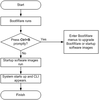
Upon power-on, the BootWare image runs to initialize hardware, and then the startup software images run to start up the entire system, as shown in Figure 2.
Figure 2 System startup process
Upgrade methods
|
Upgrading method |
Software types |
Remarks |
|
Upgrading from the CLI without using ISSU |
· BootWare image · Comware images (excluding patches) |
This method is disruptive. You must reboot the entire device to complete the upgrade. |
|
Performing an ISSU |
Comware images |
The ISSU method enables a software upgrade without service disruption. Use this method for an IRF fabric or MPU-redundant device. For more information about ISSU, see "Performing ISSU." |
|
Upgrading from the BootWare menus |
· BootWare image · Comware software images |
Use this method when the device cannot start up correctly.
Upgrade an IRF fabric from the CLI rather than the BootWare menu. The BootWare menu method increases the service downtime, because it requires that you upgrade the member devices one by one. |
This chapter only covers upgrading software from the CLI without using ISSU.
|
|
NOTE: You do not need to upgrade BootWare or Comware software for MPUs and interface cards separately. The software images are integrated for MPUs and interface cards. The interface cards upgrade automatically when you upgrade MPUs. |
Non-ISSU upgrade procedure summary
To upgrade software from the CLI without using ISSU:
1. Download the upgrade software image file.
2. Register and activate licenses for license-based images. Skip this step if no license is required or the device already has a valid running license for each license-based image.
3. (Optional.) Preload the BootWare image to the BootWare.
If a BootWare upgrade is required, you can perform this task to shorten the subsequent upgrade time. This task helps avoid upgrade problems caused by unexpected electricity failure.
If you skip this task, the device automatically upgrades the BootWare when upgrading the startup software images.
The BootWare image preloaded into the BootWare does not affect the device running status.
4. Specify the image file as the startup software image file.
5. If you are upgrading a standalone device, reboot the device. If you are upgrading an IRF fabric, reboot the entire IRF fabric.
6. Verify the upgrade.
Preparing for the upgrade
1. Use the display version command to verify the current BootWare image version and startup software version.
2. Use the release notes for the upgrade software version to evaluate the upgrade impact on your network and verify the following items:
¡ Software and hardware compatibility
¡ Version and size of the upgrade software
¡ Compatibility of the upgrade software with the current BootWare image and startup software image
3. Use the software version-matching release notes to verify whether the software images require a license. If licenses are required, register and activate licenses for each license-based software image. For more information about licensing, see "Managing licenses."
4. Use the dir command to verify that both MPUs (in standalone mode) or all MPUs (in IRF mode) have sufficient storage space for the upgrade images. If the storage space is not sufficient, delete unused files by using the delete command. For more information, see "Managing the file system."
5. Configure FTP and TFTP settings.
6. Download the upgrade image file to the root directory of a storage medium on an MPU.
For more information about FTP and TFTP configuration and operations, see "Configuring FTP" or "Configuring TFTP."
Preloading the BootWare image to BootWare
|
Task |
Command |
Remarks |
|
Load the upgrade BootWare image to the Normal area of BootWare. |
· In standalone mode: · In IRF mode: |
Specify the downloaded software image file for the file-url argument. The new BootWare image takes effect at a reboot. |
Specifying the startup image file and completing the upgrade (in standalone mode)
Perform this task in user view.
|
Step |
Command |
Remarks |
|
1. Specify main or backup startup images for the active MPU. |
· Method 1: · Method 2: |
Upgrade files must be saved in the root directory of a storage medium on the active MPU. If the storage medium is a partitioned CF card, save the files to the root directory of the first partition. Make sure the following filename format requirements are met: · If method 1 is used, the file name must use the storage-medium:/base-filename.ipe format, for example, flash:/startup.ipe. · If method 2 is used, all file names must use the storage-medium:/base-filename.bin format, for example, flash:/startup-boot.bin. |
|
2. Specify main or backup startup images for the standby MPU. |
· Method 1: · Method 2: · Method 3: · Method 4: |
To use method 3, make sure you understand the following requirements and upgrade results: · If an ISSU upgrade has been performed, use the install commit command to update the main startup images on the active MPU before software synchronization. The command ensures startup image consistency between the active MPU and the standby MPU. · If the active MPU has started up with main startup images, its main startup images are synchronized to the standby MPU. This synchronization occurs regardless of whether any change has been made to this set of startup images. · If the active MPU has started up with backup startup images, its backup startup images are synchronized to the standby MPU. This synchronization occurs regardless of whether any change has been made to this set of startup images. · Startup image synchronization will fail if any software image being synchronized is corrupted or is not available. |
|
3. Save the running configuration. |
save |
This step ensures that any configuration you have made can survive a reboot. |
|
4. Reboot the device. |
reboot |
At startup, the MPUs read the preloaded BootWare image to RAM and load the startup images. |
|
5. (Optional.) Verify the software image settings. |
display boot-loader [ slot slot-number ] |
Verify that the current software images are the same as the startup software images. |
Specifying the startup image file and completing the upgrade (in IRF mode)
Perform this task in user view.
|
Step |
Command |
Remarks |
|
1. Specify main or backup startup image files for the active MPU. |
· Method 1: · Method 2: |
Upgrade files must be saved in the root directory of a storage medium on the global active MPU. If the storage medium is a partitioned CF card, save the files to the root directory of the first partition. Make sure the following filename format requirements are met: · If method 1 is used, the file name must use the storage-medium:/base-filename.ipe format, for example, flash:/startup.ipe. · If method 2 is used, all file names must use the storage-medium:/base-filename.bin format, for example, flash:/startup-boot.bin. |
|
2. Specify the main startup images for each standby MPU in the IRF fabric. |
· Method 1: · Method 2: · Method 3: |
To use method 3, make sure you understand the following requirements and upgrade results: · If an ISSU upgrade has been performed, use the install commit command to update the main startup images on the active MPU before software synchronization. The command ensures startup image consistency between the active MPU and the standby MPU. · If the active MPU has started up with main startup images, its main startup images are synchronized to the standby MPU. This synchronization occurs regardless of whether any change has been made to this set of startup images. · If the active MPU has started up with backup startup images, its backup startup images are synchronized to the standby MPU. This synchronization occurs regardless of whether any change has been made to this set of startup images. · Startup image synchronization will fail if any software image being synchronized is corrupted or is not available. |
|
3. Save the running configuration. |
save |
This step makes sure any configuration you have made can survive a reboot. |
|
4. Reboot the IRF fabric. |
reboot |
At startup, the MPUs read the preloaded BootWare image to RAM and load the startup images. |
|
5. (Optional.) Verify the software image settings. |
display boot-loader [ chassis chassis-number [ slot slot-number ] ] |
Verify that the current software images are the same as the startup software images. |
Upgrading MBUS daughter card software
Typically, MBUS daughter card software is upgraded automatically when the startup software images are upgraded. If the auto-upgrade fails, use the mbus update command to upgrade it.
To ensure a successful upgrade, follow these guidelines:
· In an IRF fabric, save the upgrade file on the active MPU in the same chassis as the MBUS daughter card.
· Make sure no one performs any of the following operations during the upgrade:
¡ Perform an active and standby switchover.
¡ Execute the power-supply off command.
¡ Power off or reboot the device.
¡ Reboot or swap the active MPU or the card that hosts the MBUS daughter card.
To upgrade MBUS daughter card software, perform one of the following tasks in user view:
|
Task |
Command |
|
Upgrade the MBUS daughter card software on a card (in standalone mode). |
mbus update [ file filename ] slot slot-number |
|
Upgrade the MBUS daughter card software on a card (in IRF mode). |
mbus update [ file filename ] chassis chassis-number slot slot-number |
Upgrading CPLDs
To ensure a successful CPLD upgrade, follow these guidelines:
· To upgrade the CPU CPLD on an interface card in an IRF fabric, you must save the upgrade file on the active MPU that is in the same chassis as the interface card.
· Make sure no one performs any of the following operations during the upgrade:
¡ Perform an active and standby switchover.
¡ Execute the power-supply off command.
¡ Power off or reboot the device.
¡ Reboot or swap the active MPU or the card that is being upgraded.
· If you are upgrading the OAM module CPLD on an MPU, you must reboot the MPU to run the new CPLD. If you are upgrading a card CPLD or CPU CPLD, the card reboots automatically.
If you install an interface card during a CPLD upgrade, the system can supply power to the card only after the upgrade is complete.
To upgrade a CPLD on an interface card or MPU:
|
Step |
Command |
Remarks |
|
1. Set the interface card in offline state. |
a. Enter system view. b. Isolate the interface card. c. Return to user view. |
Skip this step if you are upgrading a CPLD for an MPU. In offline state, an interface card cannot forward traffic. |
|
2. Upgrade a CPLD on an interface card or MPU through the MBUS daughter card. |
· In standalone mode: · In IRF mode: |
The logicid argument specifies the CPLD type: · 0—Card (interface card or MPU) CPLD. · 1—OAM module CPLD on an MPU, or CPU CPLD on an interface card. |
Upgrading or repairing the power software on an interface card
Upgrade or repair the power software on an interface card if the card has a power failure.
To ensure a successful upgrade, follow these guidelines:
· In an IRF fabric, you must save the upgrade file on the active MPU that is in the same chassis as the card you are working with.
· Make sure no one performs any of the following operations during the upgrade:
¡ Perform an active and standby switchover.
¡ Execute the power-supply off command.
¡ Power off the device.
¡ Reboot or swap the active MPU or the card that is being upgraded.
· If the system instructs you to choose a card model during the upgrade, use the card model on the card panel as a reference to make the correct choice. The upgrade fails if you fail to enter a choice within 30 seconds or fail to choose the correct model within five attempts.
When the upgrade is complete, the card reboots automatically to run the new software.
If you install a card during a power software upgrade, the system can supply power to the card only after the upgrade is complete.
To upgrade the power software on an interface card:
|
Step |
Command |
Remarks |
|
1. Enter system view. |
system-view |
N/A |
|
2. Set the interface card in offline state. |
· In standalone mode: · In IRF mode: |
In offline state, a card cannot forward traffic. |
|
3. Return to user view. |
quit |
N/A |
|
4. Upgrade the power software on the isolated card. |
· In standalone mode: · In IRF mode: |
The command is not available for MPUs. |
Upgrading the power monitor software
Typically, the power monitor software is upgraded automatically when the startup software images are upgraded. If the auto-upgrade fails, use the pmu update command to upgrade it.
This task does not apply to the PSE9000 power module. To identify the power module model, use the display power-supply command (see Fundamentals Command Reference).
To ensure a successful upgrade, follow these guidelines:
· Save the upgrade file on the switch that holds the power monitoring module to be upgraded.
· In an IRF fabric, save the upgrade file on the active MPU that is in the same chassis as the power monitoring module.
· Make sure no one performs any of the following operations during the upgrade:
¡ Perform an active and standby switchover.
¡ Execute the power-supply off command.
¡ Power off the device.
¡ Reboot or swap the active MPU.
To upgrade the software of a power monitoring module, perform one of the following tasks in user view:
|
Task |
Command |
|
Upgrade the power monitor software (in standalone mode). |
pmu update [ file filename ] pmu-id |
|
Upgrade the power monitor software (in IRF mode). |
pmu update [ file filename ] chassis chassis-number pmu-id |
Upgrading fan monitor software
On the S12508 or S12518 switch, this task is available only for fan trays that use software version 103 and CPLD 002 (or above). After the upgrade is complete for one fan tray, you must remove the fan tray, and then reinstall it to run the upgraded software before you can continue to upgrade the other fan tray.
On the S12504 switch, this task is available only for fan trays that use software version 202 (or above).
To verify fan tray information, use the display fan verbose command.
To avoid damage to the fan monitor module, make sure no one performs any of the following operations during the upgrade:
· Remove the fan tray before the system displays the upgrade completed message.
· Perform an active/standby switchover.
· Execute the power-supply off command.
· Power off the device.
· Reboot or swap the active MPU.
To upgrade the fan monitor software of a fan tray, perform the following task in user view:
|
Step |
Command |
Remarks |
|
1. Upgrade the fan monitor software for the specified fan tray. |
· In standalone mode: · In IRF mode: |
The S12504 switch has only one fan tray. It does not support the bottom keyword. In IRF mode, you must save the upgrade file on the active MPU that is in the same chassis as the fan tray you are upgrading. |
|
2. Remove and reinstall the fan tray. |
N/A |
If the device is an S12508 or S12518 switch, perform this step. Do not perform this task before the system displays the upgrade completed message. |
|
|
NOTE: While a fan tray is being upgraded, you cannot configure the fan tray or the power modules. |
Enabling software synchronization from the active MPU to the standby MPU at startup
This feature is available only when the device is operating in standalone mode. To synchronize software from the global active MPU to other MPUs on an IRF fabric, use the irf auto-update enable command. For more information about software auto-update, see IRF in Virtual Technologies Configuration Guide.
When the standby MPU starts up, this feature examines its startup software images for version inconsistency with the current software images on the active MPU.
If the software versions are different, the standby MPU does the following:
1. Copies the current software images of the active MPU.
2. Specifies the images as startup software images.
3. Reboots with these images.
|
|
IMPORTANT: To ensure a successful synchronization in a multiuser environment, prevent users from rebooting or swapping MPUs during the software synchronization process. You can configure the information center to output the synchronization status to configuration terminals (see Network Management and Monitoring Configuration Guide). |
To enable software synchronization from the active MPU to the standby MPU at startup:
|
Step |
Command |
Remarks |
|
1. Enter system view. |
system-view |
N/A |
|
2. Enable startup software version check for the standby MPU. |
undo version check ignore |
By default, startup software version check is enabled. |
|
3. Enable software auto-update for the standby MPU. |
version auto-update enable |
By default, software version auto-update is enabled. |
Displaying and maintaining software image settings
Execute display commands in any view.
|
Task |
Command |
|
Display current software images and startup software images (in standalone mode). |
display boot-loader [ slot slot-number ] |
|
Display current software images and startup software images (in IRF mode). |
display boot-loader [ chassis chassis-number [ slot slot-number ] ] |
Non-ISSU software upgrade example (for standalone mode)
Network requirements
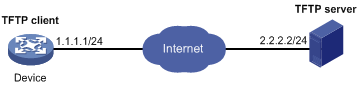
The device has two MPUs: one active MPU in slot 0 and one standby MPU in slot 1.
Use the file startup-a2105.ipe to upgrade software images for the device.
Figure 3 Network diagram
Configuration procedure
# Configure IP addresses and routes. Make sure the device and the TFTP server can reach each other. (Details not shown.)
# Complete TFTP settings on both the device and the TFTP server. (Details not shown.)
# Display information about the current software images.
<Sysname> display version
# Use TFTP to download the image file startup-a2105.ipe from the TFTP server to the root directory of the flash memory on the active MPU.
<Sysname> tftp 2.2.2.2 get startup-a2105.ipe
# (Optional.) Back up the image file to startup-a2105-backup.ipe. Skip this step if the flash memory does not have sufficient space.
<Sysname> copy startup-a2105.ipe startup-a2105_backup.ipe
# Specify startup-a2105.ipe as the main startup image file for both MPUs.
<Sysname> boot-loader file flash:/startup-a2105.ipe slot 0 main
<Sysname> boot-loader file flash:/startup-a2105.ipe slot 1 main
# Specify startup-a2105-backup.ipe as the backup startup image file for both MPUs.
<Sysname> boot-loader file flash:/startup-a2105-backup.ipe slot 0 backup
<Sysname> boot-loader file flash:/startup-a2105-backup.ipe slot 1 backup
# Verify the startup image settings.
<Sysname> display boot-loader
# Reboot the device to complete the upgrade.
<Sysname> reboot
# Verify that the device is running the correct software.
<Sysname> display version
Non-ISSU software upgrade example (for IRF mode)
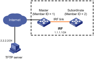
Network requirements
Use the file startup-a2105.ipe to upgrade software images for the IRF fabric in Figure 4.
Each IRF member device has two MPUs: one in slot 0 and one in slot 1. The global active MPU is in slot 0 on the master device.
Configuration procedure
# Configure IP addresses and routes. Make sure the device and the TFTP server can reach each other. (Details not shown.)
# Complete TFTP settings on both the device and the TFTP server. (Details not shown.)
# Display information about the current software images.
<Sysname> display version
# Use TFTP to download the image file startup-a2105.ipe from the TFTP server to the root directory of the flash memory on the global active MPU.
<Sysname> tftp 2.2.2.2 get startup-a2105.ipe
# (Optional.) Back up the image file to startup-a2105-backup.ipe on the global active MPU. Skip this step if the flash memory does not have sufficient space.
<Sysname> copy startup-a2105.ipe startup-a2105_backup.ipe
# Specify startup-a2105.ipe as the main startup image file for all MPUs.
<Sysname> boot-loader file flash:/startup-a2105.ipe chassis 1 slot 0 main
<Sysname> boot-loader file flash:/startup-a2105.ipe chassis 1 slot 1 main
<Sysname> boot-loader file flash:/startup-a2105.ipe chassis 2 slot 0 main
<Sysname> boot-loader file flash:/startup-a2105.ipe chassis 2 slot 1 main
# Specify startup-a2105-backup.ipe as the backup startup image file for all MPUs.
<Sysname> boot-loader file flash:/startup-a2105-backup.ipe chassis 1 slot 0 backup
<Sysname> boot-loader file flash:/startup-a2105-backup.ipe chassis 1 slot 1 backup
<Sysname> boot-loader file flash:/startup-a2105-backup.ipe chassis 2 slot 0 backup
<Sysname> boot-loader file flash:/startup-a2105-backup.ipe chassis 2 slot 1 backup
# Verify the startup image settings.
<Sysname> display boot-loader
# Reboot the IRF fabric to complete the upgrade.
<Sysname> reboot
# Verify that the IRF fabric is running the correct software.
<Sysname> display version