- Table of Contents
-
- 11-Security Configuration Guide
- 00-Preface
- 01-Security Overview
- 02-AAA Configuration
- 03-802.1X Configuration
- 04-MAC Authentication Configuration
- 05-Portal Configuration
- 06-Password Control Configuration
- 07-Public Key Configuration
- 08-IPsec Configuration
- 09-SSH Configuration
- 10-Blacklist Configuration
- 11-TCP and ICMP Attack Protection Configuration
- 12-IP Source Guard Configuration
- 13-ARP Attack Protection Configuration
- 14-ND Attack Defense Configuration
- 15-URPF Configuration
- 16-PKI Configuration
- 17-SSL Configuration
- 18-FIPS Configuration
- 19-Attack Detection and Protection Configuration
- Related Documents
-
| Title | Size | Download |
|---|---|---|
| 08-IPsec Configuration | 338.27 KB |
Contents
IPsec for IPv6 routing protocols
IPsec tunnel application restrictions
Applying an IPsec policy group to an interface
Configuring the IPsec session idle timeout
Enabling ACL checking of de-encapsulated IPsec packets
Configuring the IPsec anti-replay function
Configuring packet information pre-extraction
Configuring IPsec for IPv6 routing protocols
Displaying and maintaining IPsec
Configuring a manual mode IPsec tunnel for IPv4 packets
Configuring an IKE-based IPsec tunnel for IPv4 packets
Relationship between IKE and IPsec
Configuring a name for the local security gateway
Setting the NAT keepalive timer
Disabling next payload field checking
Displaying and maintaining IKE
Failing to establish an IPsec tunnel
The term "router" in this document refers to both routers and Layer 3 switches.
IPsec is available only on Ethernet interface cards.
Overview
IP Security (IPsec) is a security framework defined by the IETF for securing IP communications. It is a Layer 3 VPN technology that transmits data in a secure tunnel established between two endpoints.
IPsec provides the following security services in insecure network environments:
· Confidentiality—The sender encrypts packets before transmitting them over the Internet, protecting the packets from being eavesdropped en route.
· Data integrity—The receiver verifies the packets received from the sender to make sure they are not tampered with during transmission.
· Data origin authentication—The receiver verifies the authenticity of the sender.
· Anti-replay—The receiver examines packets and drops outdated and duplicate packets.
IPsec delivers the following benefits:
· Reduced key negotiation overheads and simplified maintenance by supporting the IKE protocol. IKE provides automatic key negotiation and automatic IPsec security association (SA) setup and maintenance.
· Good compatibility. You can apply IPsec to all IP-based application systems and services without modifying them.
· Encryption on a per-packet rather than per-flow basis. Per-packet encryption allows for flexibility and greatly enhances IP security.
IPsec comprises a set of protocols, including Authentication Header (AH), Encapsulating Security Payload (ESP), Internet Key Exchange (IKE), and algorithms for authentication and encryption. AH and ESP provides security services and IKE performs automatic key exchange. For more information about IKE, see "Configuring IKE."
IPsec can protect both IPv4 and IPv6 packets.
Basic concepts
Security protocols
IPsec comes with two security protocols:
· AH (protocol 51)—Provides data origin authentication, data integrity, and anti-replay services by adding an AH header to each IP packet. AH is suitable only for transmitting non-critical data because it cannot prevent eavesdropping, although it can prevent data tampering. AH supports authentication algorithms such as MD5 and SHA-1.
· ESP (protocol 50)—Provides data encryption as well as data origin authentication, data integrity, and anti-replay services by inserting an ESP header and an ESP trailer in IP packets. Unlike AH, ESP encrypts data before encapsulating the data to guarantee data confidentiality. ESP supports encryption algorithms such as DES, 3DES, and AES, and authentication algorithms such as MD5 and SHA-1. The authentication function is optional to ESP.
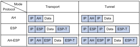
Both AH and ESP provide authentication services, but the authentication service provided by AH is stronger. In practice, you can choose either or both security protocols. When both AH and ESP are used, an IP packet is encapsulated first by ESP and then by AH. Figure 1 shows the format of IPsec packets.
Security association
A security association is an agreement negotiated between two communicating parties called IPsec peers. It comprises a set of parameters for data protection, including security protocols, encapsulation mode, authentication and encryption algorithms, and shared keys and their lifetime. SAs can be set up manually or through IKE.
An SA is unidirectional. At least two SAs are needed to protect data flows in a bidirectional communication. If two peers want to use both AH and ESP to protect data flows between them, they construct an independent SA for each protocol.
An SA is identified by a triplet, which consists of the security parameter index (SPI), destination IP address, and security protocol identifier (AH or ESP).
An SPI is a 32-bit number for uniquely identifying an SA. It is transmitted in the AH/ESP header. A manually configured SA requires an SPI to be specified manually for it. An IKE-created SA will have an SPI generated at random.
A manually configured SA never ages out. An IKE created SA has a specified period of lifetime, which comes in two types:
· Time-based lifetime—Defines how long the SA can be valid after it is created.
· Traffic-based lifetime—Defines the maximum traffic that the SA can process.
The SA becomes invalid when either of the lifetime timers expires. Before the SA expires, IKE negotiates a new SA, which takes over immediately after its creation.
Encapsulation modes
IPsec supports the following IP packet encapsulation modes:
· Tunnel mode—IPsec protects the entire IP packet, including both the IP header and the payload. It uses the entire IP packet to calculate an AH or ESP header, and then encapsulates the original IP packet and the AH or ESP header with a new IP header. If you use ESP, an ESP trailer is also encapsulated. Tunnel mode is typically used for protecting gateway-to-gateway communications.
· Transport mode—IPsec protects only the IP payload. It uses only the IP payload to calculate the AH or ESP header, and inserts the calculated header between the original IP header and payload. If you use ESP, an ESP trailer is also encapsulated. The transport mode is typically used for protecting host-to-host or host-to-gateway communications.
Figure 1 shows how the security protocols encapsulate an IP packet in different encapsulation modes.
Figure 1 Encapsulation by security protocols in different modes
Authentication algorithms and encryption algorithms
· Authentication algorithms:
IPsec uses hash algorithms to perform authentication. A hash algorithm produces a fixed-length digest for an arbitrary-length message. IPsec peers respectively calculate message digests for each packet. If the resulting digests are identical, the packet is considered intact.
IPsec supports the following hash algorithms for authentication:
¡ MD5—Takes a message of arbitrary length as input and produces a 128-bit message digest.
¡ SHA-1—Takes a message of a maximum length less than the 64th power of 2 in bits as input and produces a 160-bit message digest.
Compared with SHA-1, MD5 is faster but less secure.
· Encryption algorithms:
IPsec mainly uses symmetric encryption algorithms, which encrypt and decrypt data by using the same keys. The following encryption algorithms are available for IPsec on the device:
¡ DES—Encrypts a 64-bit plain text block with a 56-bit key. DES is the least secure but the fastest algorithm. It is sufficient for general security requirements.
¡ 3DES—Encrypts plain text data with three 56-bit DES keys. The key length totals up to 168 bits. It provides moderate security strength and is slower than DES.
¡ AES—Encrypts plain text data with a 128-bit, 192-bit, or 256-bit key. AES provides the highest security strength and is slower than 3DES.
IPsec SA setup modes
There are two IPsec SA setup modes:
· Manual mode—In this mode, you manually configure and maintain all SA settings. Advanced features like periodical key update are not available. However, this mode implements IPsec independently of IKE.
· ISAKMP mode—In this mode, IKE automatically negotiates and maintains IPsec SAs for IPsec. This mode is available only for FIPS mode.
If the number of IPsec tunnels in your network is small, use the manual mode. If the number of IPsec tunnels is large, use the ISAKMP mode.
IPsec tunnel
An IPsec tunnel is a bidirectional channel created between two peers. An IPsec tunnel comprises one or more pairs of SAs.
IPsec for IPv6 routing protocols
You can use IPsec to protect routing information and defend against attacks for these IPv6 routing protocols: OSPFv3, IPv6 BGP, and RIPng. IPsec enables these IPv6 routing protocols to encapsulate outbound protocol packets and de-encapsulate inbound protocol packets with the AH or ESP protocol. If an inbound protocol packet is not IPsec protected, or fails to be de-encapsulated, for example, due to decryption or authentication failure, the routing protocol discards that packet.
You must manually configure SA parameters in an IPsec policy for IPv6 routing protocols. The IKE key exchange mechanism is applicable only to one-to-one communications. IPsec cannot implement automatic key exchange for one-to-many communications on a broadcast network, where routers must use the same SA parameters (SPI and key) to process packets for a routing protocol.
IPsec RRI
IPsec Reverse Route Inject (RRI) enables an IPsec tunnel gateway to automatically add static routes destined for protected private networks or peer IPsec tunnel gateways to a routing table. In an MPLS L3VPN network, IPsec RRI can add static routes to VPN instances' routing tables.
You can advertise the static routes created by IPsec RRI in the internal network. IPsec RRI can quickly create new routes for forwarding IPsec VPN traffic when an active link fails in a load balanced or stateful failover environment, or when IPsec VPN traffic cannot reach the peer gateway through the default local gateway.
Protocols and standards
· RFC 2401, Security Architecture for the Internet Protocol
· RFC 2402, IP Authentication Header
· RFC 2406, IP Encapsulating Security Payload
· RFC 4552, Authentication/Confidentiality for OSPFv3
Implementing IPsec
IPsec can be implemented based on ACLs or applications:
· ACL-based IPsec uses ACLs to identify the data flows to be protected. To implement ACL-based IPsec, configure IPsec policies, reference ACLs in the policies, and apply the policies to physical interfaces (see "Implementing ACL-based IPsec"). By using ACLs, you can customize IPsec policies as needed, implementing IPsec flexibly.
· Application-based IPsec protects the packets of a service. This IPsec implementation method can be used to protect IPv6 routing protocols. It does not require any ACL, nor does it depend on the routing mechanism. To configure service-based IPsec, configure manual IPsec policies and bind the policies to an IPv6 routing protocol. See "Configuring IPsec for IPv6 routing protocols."
ACL-based IPsec is available for both IPv4 and IPv6 packets, and the configuration procedures are the same for IPv4 and IPv6.
IPsec tunnel application restrictions
The IPsec feature is designed to protect only traffic that is generated by the device and traffic that is destined for the device. Providing IPsec protection for user traffic will severely decrease performance. To avoid this issue, H3C recommends that you not include any rules to match traffic forwarded through the device. For example, you can configure an IPsec tunnel to protect log messages the device sends to a log server. However, do not use an IPsec tunnel to protect traffic that is forwarded by the device for two hosts. For more information about configuring an ACL for IPsec, see "Configuring an ACL."
Implementing ACL-based IPsec
This feature is available only for FIPS mode.
The following is the generic configuration procedure for implementing ACL-based IPsec:
1. Configure an ACL for identifying data flows to be protected.
2. Configure IPsec proposals to specify the security protocols, authentication and encryption algorithms, and encapsulation mode.
3. Configure an IPsec policy group to associate data flows with the IPsec proposals and specify the SA negotiation mode, the peer IP addresses (the start and end points of the IPsec path), the required keys, and the SA lifetime.
4. Apply the IPsec policies to interfaces to finish IPsec configuration.
Complete the following tasks to configure ACL-based IPsec:
|
Task |
Remarks |
|
Required. Basic IPsec configuration. |
|
|
Optional. |
|
|
Optional. |
|
|
Optional. |
|
|
Optional. |
|
|
Optional. |
|
|
Optional. |
Typically, IKE uses UDP port 500 for communication, and AH and ESP use the protocol numbers 51 and 50 respectively. Make sure that flows of these protocols are not denied on the interfaces with IKE or IPsec configured.
Configuring an ACL
ACLs can be used to identify traffic. They are widely used in scenarios where traffic identification is desired, such as QoS and IPsec.
Keywords in ACL rules
IPsec uses ACLs to identify data flows. An ACL is a collection of ACL rules. Each ACL rule is a deny or permit statement. A permit statement identifies a data flow protected by IPsec, and a deny statement identifies a data flow that is not protected by IPsec. With IPsec, a packet is matched against the referenced ACL rules and processed according to the first rule that it matches:
· Each ACL rule matches both the outbound traffic and the returned inbound traffic.
· In the outbound direction, if a permit statement is matched, IPsec considers that the packet requires protection and continues to process it. If a deny statement is matched or no match is found, IPsec considers that the packet does not require protection and delivers it to the next function module.
· In the inbound direction:
¡ Non-IPsec packets that match a permit statement are dropped.
¡ IPsec packets destined for the device itself are de-encapsulated. The de-encapsulated packets are compared against the ACL rules. Only those that match a permit statement are processed by other modules. Other packets are dropped.
When defining ACL rules for IPsec, follow these guidelines:
· Permit only data flows that need to be protected and use the any keyword with caution. With the any keyword specified in a permit statement, all outbound traffic matching the permit statement will be protected by IPsec and all inbound IPsec packets matching the permit statement will be received and processed, but all inbound non-IPsec packets will be dropped. This will cause the inbound traffic that does not need IPsec protection to be all dropped.
· Avoid statement conflicts in the scope of IPsec policy groups. When creating a deny statement, be careful with its matching scope and matching order relative to permit statements. The policies in an IPsec policy group have different match priorities. ACL rule conflicts between them are prone to cause mistreatment of packets. For example, when configuring a permit statement for an IPsec policy to protect an outbound traffic flow, you must avoid the situation that the traffic flow matches a deny statement in a higher priority IPsec policy. Otherwise, the packets will be sent out as normal packets. If they match a permit statement at the receiving end, they will be dropped by IPsec.
· In an IPsec policy, the device supports configuring only one ACL. Make sure to configure all rules in one ACL for the IPsec policy to reference.
Configuring ACL rules
To make sure that SAs can be set up and the traffic protected by IPsec can be processed correctly at the remote peer, on the remote peer, create a mirror image ACL rule for each ACL rule created at the local peer.
If the ACL rules on peers do not form mirror images of each other, SAs can be set up only when both of the following requirements are met:
· The range specified by an ACL rule on one peer is covered by its counterpart ACL rule on the other peer.
· The peer with the narrower rule initiates SA negotiation. If a wider ACL rule is used by the SA initiator, the negotiation request might be rejected because the matching traffic is beyond the scope of the responder.
Protection mode
Data flows can be protected in standard mode, where one tunnel protects one data flow. The data flow permitted by an ACL rule is protected by one tunnel that is established solely for it. The standard data flow protection mode is available only for FIPS mode.
For more information about ACL configuration, see ACL and QoS Configuration Guide.
To use IPsec in combination with QoS, make sure that IPsec's ACL classification rules match the QoS classification rules. If the rules do not match, QoS might classify the packets of one IPsec SA to different queues, causing packets to be sent out of order. When the anti-replay function is enabled, IPsec will discard the packets beyond the anti-replay window in the inbound direction, resulting in packet loss. For more information about QoS classification rules, see ACL and QoS Configuration Guide.
Configuring an IPsec proposal
An IPsec proposal, part of an IPsec policy, defines the security parameters for IPsec SA negotiation, including the security protocol, the encryption and authentication algorithms, and the encapsulation mode.
You can configure up to 10000 IPsec proposals in the system.
To configure an IPsec proposal:
|
Step |
Command |
Remarks |
|
1. Enter system view. |
system-view |
N/A |
|
2. Create an IPsec proposal and enter its view. |
ipsec proposal proposal-name |
By default, no IPsec proposal exists. |
|
3. Specify the security protocol for the IPsec proposal. |
transform { ah | ah-esp | esp } |
Optional. ESP by default. You can configure security algorithms for a security protocol only after you select the protocol. For example, you can specify the ESP-specific security algorithms only when you select ESP as the security protocol. In non-FIPS mode, ESP supports three IP packet protection schemes: encryption only, authentication only, or both encryption and authentication. In FIPS mode, ESP must use both the authentication and encryption algorithms. |
|
4. Specify the security algorithms. |
· Specify the encryption algorithm for ESP: · Specify the authentication algorithm for ESP: · Specify the authentication algorithm for AH: |
Configure at least one command. By default, ESP uses the DES encryption algorithm and the MD5 authentication algorithm in non-FIPS mode, and it uses the AES-128 encryption algorithm and the SHA1 authentication algorithm in FIPS mode. By default, AH uses the MD5 authentication algorithm in non-FIPS mode and uses the SHA1 authentication algorithm in FIPS mode. The 3des, des, and md5 keywords are not available for ESP in FIPS mode. The md5 keyword is not available for AH in FIPS mode. |
|
5. Specify the IP packet encapsulation mode for the IPsec proposal. |
encapsulation-mode { transport | tunnel } |
Optional. Tunnel mode by default. Transport mode applies only when the source and destination IP addresses of data flows match those of the IPsec tunnel. IPsec for IPv6 routing protocols supports only the transport mode. |
Changes to an IPsec proposal affect only SAs negotiated after the changes. To apply the changes to existing SAs, execute the reset ipsec sa command to clear the SAs so that they can be set up using the updated parameters.
Configuring an IPsec policy
IPsec policies define which IPsec proposals should be used to protect which data flows. An IPsec policy is uniquely identified by its name and sequence number.
IPsec policies include the following categories:
· Manual IPsec policy—The parameters are configured manually, such as the keys, the SPIs, and the IP addresses of the two ends in tunnel mode.
· IPsec policy that uses IKE—The parameters are automatically negotiated through IKE.
Configuring a manual IPsec policy
To guarantee successful SA negotiations, follow these guidelines when configuring manual IPsec policies at the two ends of an IPsec tunnel:
· The IPsec policies at the two ends must have IPsec proposals that use the same security protocols, security algorithms, and encapsulation mode.
· The remote IP address configured on the local end must be the same as the IP address of the remote end.
· At each end, configure parameters for both the inbound SA and the outbound SA and make sure that different SAs use different SPIs.
· The local inbound SA must use the same SPI and keys as the remote outbound SA. The same is true of the local outbound SA and remote inbound SA.
· The keys for the local and remote inbound and outbound SAs must be in the same format. For example, if the local inbound SA uses a key in characters, the local outbound SA and remote inbound and outbound SAs must use keys in characters.
Follow these guidelines when you configure an IPsec policy for an IPv6 routing protocol:
· You do not need to configure ACLs or IPsec tunnel addresses.
· Within a certain routed network scope, the IPsec proposals used by the IPsec policies on all switches must have the same security protocols, security algorithms, and encapsulation mode. For OSPFv3, the scope can be directly connected neighbors or an OSPFv3 area. For RIPng, the scope can be directly connected neighbors or a RIPng process. For IPv6 BGP, the scope can be directly connected neighbors or a neighbor group.
· All SAs (both inbound and outbound) within the routed network scope must use the same SPI and keys.
· Configure the keys on all switches within the routed network scope in the same format. For example, if you enter the keys in hexadecimal format on one switch, do so across the routed network scope.
Before you configure a manual IPsec policy, configure ACLs used for identifying protected traffic and IPsec proposals. ACLs are not required for IPsec policies for an IPv6 protocol.
To configure a manual IPsec policy:
|
Step |
Command |
Remarks |
|
1. Enter system view. |
system-view |
N/A |
|
2. Create a manual IPsec policy and enter its view. |
ipsec policy policy-name seq-number manual |
By default, no IPsec policy exists. |
|
3. Assign an ACL to the IPsec policy. |
security acl acl-number |
Not needed for IPsec policies to be applied to IPv6 routing protocols and required for other applications. By default, an IPsec policy references no ACL. The ACL supports match criteria of the VPN attribute. An IPsec policy can reference only one ACL. If you apply multiple ACLs to an IPsec policy, only the last one takes effect. |
|
4. Assign an IPsec proposal to the IPsec policy. |
proposal proposal-name |
By default, an IPsec policy references no IPsec proposal. A manual IPsec policy can reference only one IPsec proposal. To change an IPsec proposal for an IPsec policy, you must remove the reference first. |
|
5. Configure the local address and the remote address of the IPsec tunnel. |
· Configure the local address of the IPsec tunnel: · Configure the remote address of the IPsec tunnel: |
Not needed for IPsec policies to be applied to IPv6 routing protocols and required for other applications. By default, the tunnel local and remote addresses are not configured. You can configure the tunnel local and remote addresses only in FIPS mode. |
|
6. Configure an SPI for an SA. |
sa spi { inbound | outbound } { ah | esp } spi-number |
By default, no SPI is configured for an SA. |
|
7. Configure keys for the SA. |
· Configure an authentication key in hexadecimal for AH: · Configure an authentication key in characters
for AH: · Configure a key in characters for ESP: · Configure an authentication key in hexadecimal for ESP: · Configure an encryption key in hexadecimal for
ESP: |
Configure keys correctly for the security protocol (AH or ESP) you have specified. If you configure a key in two modes: string and hexadecimal, only the last configured one will be used. If you configure a key in characters for ESP, the device automatically generates an authentication key and an encryption key for ESP. The sa string-key command is not available for FIPS mode. |
|
|
NOTE: You cannot change the creation mode of an IPsec policy from manual to through IKE, or vice versa. To create an IPsec policy that uses IKE, delete the manual IPsec policy, and then use IKE to configure an IPsec policy. |
Configuring an IPsec policy that uses IKE
To configure an IPsec policy that uses IKE, use one of the following methods:
· Directly configure it by configuring the parameters in IPsec policy view.
· Configure it by referencing an existing IPsec policy template with the parameters to be negotiated configured. A device referencing an IPsec policy that is configured in this way cannot initiate SA negotiation but can respond to a negotiation request. The parameters not defined in the template will be determined by the initiator. This method applies to scenarios where the remote end's information, such as the IP address, is unknown.
Before you configure an IPsec policy that uses IKE, complete the following tasks:
· Configure the ACLs and the IPsec proposals for the IPsec policy.
· Configure the IKE peer. For more information about IKE peer configuration, see "Configuring IKE."
The parameters for the local and remote ends must match.
To configure an IPsec policy that uses IKE:
|
Step |
Command |
Remark |
|
1. Enter system view. |
system-view |
N/A |
|
2. Create an IPsec policy that uses IKE and enter its view. |
ipsec policy policy-name seq-number isakmp |
By default, no IPsec policy exists. The isakmp mode is available only for FIPS mode. |
|
3. Configure an IPsec connection name. |
connection-name name |
Optional. By default, no IPsec connection name is configured. This command is available only for FIPS mode. |
|
4. Assign an ACL to the IPsec policy. |
security acl acl-number [ aggregation ] |
By default, an IPsec policy references no ACL. This command is available only for FIPS mode. |
|
5. Assign IPsec proposals to the IPsec policy. |
proposal proposal-name&<1-6> |
By default, an IPsec policy references no IPsec proposal. |
|
6. Specify an IKE peer for the IPsec policy. |
ike-peer peer-name |
An IPsec policy cannot reference any IKE peer that is already referenced by an IPsec profile, and vice versa. This command is available only for FIPS mode. |
|
7. Enable and configure the perfect forward secrecy feature for the IPsec policy. |
pfs { dh-group2 | dh-group5 | dh-group14 } |
Optional. By default, the PFS feature is not used for negotiation. For more information about PFS, see "Configuring IKE." This command is available only for FIPS mode. |
|
8. Set the SA lifetime. |
sa duration { time-based seconds | traffic-based kilobytes } |
Optional. By default, the global SA lifetime is used. This command is available only for FIPS mode. |
|
9. Enable the IPsec policy. |
policy enable |
Optional. Enabled by default. This command is available only for FIPS mode. |
|
10. Return to system view. |
quit |
N/A |
|
11. Set the global SA lifetime. |
ipsec sa global-duration { time-based seconds | traffic-based kilobytes } |
Optional. 3600 seconds for time-based SA lifetime by default. 1843200 kilobytes for traffic-based SA lifetime by default. This command is available only for FIPS mode. |
Applying an IPsec policy group to an interface
This function is available only for FIPS mode.
An IPsec policy group is a collection of IPsec policies with the same name but different sequence numbers. In an IPsec policy group, an IPsec policy with a smaller sequence number has a higher priority.
You can apply an IPsec policy group to a logical or physical interface to protect certain data flows. To cancel the IPsec protection, remove the application of the IPsec policy group.
For each packet to be sent out an IPsec protected interface, the system looks through the IPsec policies in the IPsec policy group in ascending order of sequence numbers. If an IPsec policy matches the packet, the system uses the IPsec policy to protect the packet. If no match is found, the system sends the packet out without IPsec protection.
An interface can reference only one IPsec policy group. An IPsec policy that uses IKE can be applied to more than one interface, but a manual IPsec policy can be applied to only one interface.
To apply an IPsec policy group to an interface:
|
Step |
Command |
Remarks |
|
1. Enter system view. |
system-view |
N/A |
|
2. Enter interface view. |
interface interface-type interface-number |
Only VLAN interfaces and Layer 3 Ethernet interfaces support an IPsec policy group. |
|
3. Apply an IPsec policy group to the interface. |
ipsec policy policy-name |
N/A |
Configuring the IPsec session idle timeout
An IPsec session is created when the first packet matching an IPsec policy arrives. Also created is an IPsec session entry, which records the quintuplet (source IP address, destination IP address, protocol number, source port, and destination port) and the matched IPsec tunnel.
An IPsec session is automatically deleted after the idle timeout expires.
Subsequent data flows search the session entries according to the quintuplet to find a matched item. If found, the data flows are processed according to the tunnel information. Otherwise, they are processed according to the original IPsec process: search the policy group or policy at the interface, and then the matched tunnel.
The session processing mechanism of IPsec saves intermediate matching procedures, improving the IPsec forwarding efficiency.
To set the IPsec session idle timeout:
|
Step |
Command |
Remark |
|
1. Enter system view. |
system-view |
N/A |
|
2. Set the IPsec session idle timeout. |
ipsec session idle-time seconds |
Optional. 300 seconds by default. This command is available only for FIPS mode. |
Enabling ACL checking of de-encapsulated IPsec packets
In tunnel mode, the IP packet that was encapsulated in an inbound IPsec packet might not be an object that is specified by an ACL to be protected. For example, a forged packet is not an object to be protected. If you enable ACL checking of de-encapsulated IPsec packets, all packets failing the checking will be discarded, improving the network security.
To enable ACL checking of de-encapsulated IPsec packets:
|
Step |
Command |
Remarks |
|
1. Enter system view. |
system-view |
N/A |
|
2. Enable ACL checking of de-encapsulated IPsec packets. |
ipsec decrypt check |
Optional. Enabled by default. This command is available only for FIPS mode. |
Configuring the IPsec anti-replay function
This function is available only for FIPS mode.
The IPsec anti-replay function protects networks against anti-replay attacks by using a sliding window mechanism called anti-replay window. This function checks the sequence number of each received IPsec packet against the current IPsec packet sequence number range of the sliding window. If the sequence number is not in the current sequence number range, the packet is considered a replayed packet and is discarded.
IPsec packet de-encapsulation involves complicated calculation. De-encapsulation of replayed packets not only makes no sense, but also consumes large amounts of resources and degrades performance, resulting in DoS. IPsec anti-replay checking, when enabled, is performed before the de-encapsulation process, reducing resource waste.
In some cases, however, the sequence numbers of some normal service data packets might be out of the current sequence number range, and the IPsec anti-replay function might drop them as well, affecting the normal communications. If this happens, disable IPsec anti-replay checking or adjust the size of the anti-replay window as required.
IPsec anti-replay checking does not affect manually created IPsec SAs. According to the IPsec protocol, only IPsec SAs negotiated by IKE support anti-replay checking.
|
|
IMPORTANT: · IPsec anti-replay checking is enabled by default. Do not disable it unless it needs to be disabled. · A wider anti-replay window results in higher resource cost and more system performance degradation, which is against the original intention of the IPsec anti-replay function. Specify an anti-replay window size that is as small as possible. |
To configure IPsec anti-replay checking:
|
Step |
Command |
Remarks |
|
1. Enter system view. |
system-view |
N/A |
|
2. Enable IPsec anti-replay checking. |
ipsec anti-replay check |
Optional. Enabled by default. This command is available only for FIPS mode. |
|
3. Set the size of the IPsec anti-replay window. |
ipsec anti-replay window width |
Optional. 32 by default. This command is available only for FIPS mode. |
Configuring packet information pre-extraction
If you apply both an IPsec policy and QoS policy to an interface, by default, the interface first uses IPsec and then QoS to process IP packets, and QoS classifies packets by the headers of IPsec-encapsulated packets. If you want QoS to classify packets by the headers of the original IP packets, enable the packet information pre-extraction feature.
For more information about QoS policy and classification, see ACL and QoS Configuration Guide.
To configure packet information pre-extraction:
|
Step |
Command |
Remarks |
|
1. Enter system view. |
system-view |
N/A |
|
2. Enter IPsec policy view. |
ipsec policy policy-name seq-number [ isakmp | manual ] |
This command is available only for FIPS mode. |
|
3. Enable packet information pre-extraction. |
qos pre-classify |
Disabled by default. This command is available only for FIPS mode. |
Enabling invalid SPI recovery
When the security gateway at one end of an IPsec tunnel loses its SAs due to rebooting or any other reason, its peer security gateway might not know the problem and send IPsec packets to it. These packets will be discarded by the receiver because the receiver cannot find appropriate SAs for them, resulting in a traffic blackhole. This situation changes only after the concerned SAs on the sender get aged out and new SAs are established between the two peers. To prevent such service interruption, configure the invalid SPI recovery feature.
The invalid SPI recovery feature allows the receiver to send an INVALID SPI NOTIFY message to tell the sender the invalid SPIs. Upon receiving the message, the sender immediately deletes the corresponding SAs. The subsequent traffic triggers the two peers to set up new SAs for data transmission.
Because attackers might exploit INVALID SPI NOTIFY messages to attack the IPsec packet sender (DoS attack), the invalid SPI recovery feature is disabled by default, making the receiver discard packets with invalid SPIs.
To enable invalid SPI recovery:
|
Step |
Command |
Remarks |
|
1. Enter system view. |
system-view |
N/A |
|
2. Enable invalid SPI recovery. |
ipsec invalid-spi-recovery enable |
Optional. Disabled by default. This command is available only for FIPS mode. |
Configuring IPsec RRI
This function is available only for FIPS mode.
IPsec RRI operates in static mode or dynamic mode.
Static IPsec RRI
Static IPsec RRI creates static routes based on the destination address information in the ACL that the IPsec policy references. The next hop address of the route is a user specified remote peer address, or the IP address of the remote tunnel endpoint.
Static IPsec RRI creates static routes immediately after you enable IPsec RRI in an IPsec policy and apply the IPsec policy. When you disable RRI, or remove the ACL or the peer gateway IP address from the policy, IPsec RRI deletes all static routes it has created.
The static mode applies to scenarios where the topologies of branch networks seldom change.
Dynamic IPsec RRI
Dynamic IPsec RRI dynamically creates static routes based on IPsec SAs. In each static route, the destination address is the address of a protected branch network, and the next hop is the user-specified remote peer address or the remote tunnel endpoint's address learned during IPsec SA negotiation.
Dynamic IPsec RRI creates static routes when the IPsec SAs are established, and deletes the static routes when the IPsec SAs are deleted.
The dynamic mode applies to scenarios where the topologies of branch networks change frequently. For example, when branches have dial-in users, you can configure dynamic IPsec RRI to avoid frequent configuration changes that are otherwise required on the headquarters gateway.
A good practice is to configure IPsec RRI on a headquarters gateway to create static routes for the IPsec tunnels to branches. For the static routes, you can perform the following operations:
· Change their route preference for ECMP routing or route backup. If multiple routes to the same destination have the same preference, traffic is balanced among them. If multiple routes to the same destination have different preference values, the route with the highest preference forwards traffic and all other routes are backup routes.
· Change their tag value so the gateway can control the use of the static routes based on routing policies.
To configure IPsec RRI:
|
Step |
Command |
Remarks |
|
1. Enter system view. |
system-view |
N/A |
|
2. Enter IPsec policy view. |
ipsec policy policy-name seq-number [ isakmp | manual ] |
The isakmp keyword is available only for FIPS mode. |
|
3. Enable IPsec RRI. |
reverse-route [ remote-peer ip-address [ gateway | static ] | static ] |
Disabled by default. To enable static IPsec RRI, specify the static keyword. If the keyword is not specified, dynamic IPsec RRI is enabled. |
|
4. Change the preference of the static routes created by IPsec RRI. |
reverse-route preference preference-value |
Optional. 60 by default. This command is available only for FIPS mode. |
|
5. Set a tag for the static routes created by IPsec RRI. |
reverse-route tag tag-value |
Optional. 0 by default. This command is available only for FIPS mode. |
IPsec RRI can operate in both tunnel mode and transport mode.
When you change the route attributes, static IPsec RRI deletes all static routes it has created and creates new static routes. In contrast, dynamic IPsec RRI applies the new attributes only to subsequent static routes. It does not delete or modify static routes it has created.
Configuring IPsec for IPv6 routing protocols
Complete the following tasks to configure IPsec for IPv6 routing protocols:
|
Task |
Remarks |
|
Required. |
|
|
Required. ACLs and IPsec tunnel addresses are not needed. |
|
|
Applying an IPsec policy to an IPv6 routing protocol |
Required. See Layer 3—IP Routing Configuration Guide. |
|
|
IMPORTANT: Do not apply an IPsec policy used for an IPv6 routing protocol to an interface. If you do so, the interface will drop all packets, because the IPsec policy references no ACL. |
Displaying and maintaining IPsec
|
Task |
Command |
Remarks |
|
Display IPsec policy information. |
display ipsec policy [ brief | name policy-name [ seq-number ] ] [ | { begin | exclude | include } regular-expression ] |
Available in any view. |
|
Display IPsec proposal information. |
display ipsec proposal [ proposal-name ] [ | { begin | exclude | include } regular-expression ] |
Available in any view. |
|
Display IPsec SA information. |
display ipsec sa [ brief | duration | policy policy-name [ seq-number ] | remote ip-address ] [ | { begin | exclude | include } regular-expression ] |
Available in any view. |
|
Display IPsec session information. |
display ipsec session [ tunnel-id integer ] [ | { begin | exclude | include } regular-expression ] |
Available in any view. This command is available only for FIPS mode. |
|
Display IPsec packet statistics. |
display ipsec statistics [ tunnel-id integer ] [ | { begin | exclude | include } regular-expression ] |
Available in any view. |
|
Display IPsec tunnel information. |
display ipsec tunnel [ | { begin | exclude | include } regular-expression ] |
Available in any view. |
|
Clear SAs. |
reset ipsec sa [ parameters dest-address protocol spi | policy policy-name [ seq-number ] | remote ip-address ] |
Available in user view. The parameters and remote keywords are available only for FIPS mode. |
|
Clear IPsec sessions. |
reset ipsec session [ tunnel-id integer ] |
Available in user view. This command is available only for FIPS mode. |
|
Clear IPsec statistics. |
reset ipsec statistics |
Available in user view. |
IPsec configuration examples
Configuring a manual mode IPsec tunnel for IPv4 packets
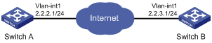
This configuration example is applicable only to switches operating in FIPS mode.
Network requirements
As shown in Figure 2, configure an IPsec tunnel between Switch A and Switch B to protect data flows between Switch A and Switch B. Configure the tunnel to use the security protocol ESP, the encryption algorithm AES 128, and the authentication algorithm SHA1-HMAC-96.
Configuration procedure
1. Configure Switch A:
# Assign an IP address to VLAN-interface 1.
<SwitchA> system-view
[SwitchA] interface vlan-interface 1
[SwitchA-Vlan-interface1] ip address 2.2.2.1 255.255.255.0
[SwitchA-Vlan-interface1] quit
# Define an ACL to identify data flows between Switch A and Switch B.
[SwitchA] acl number 3101
[SwitchA-acl-adv-3101] rule 0 permit ip source 2.2.2.1 0 destination 2.2.3.1 0
[SwitchA-acl-adv-3101] rule 5 permit ip source 2.2.3.1 0 destination 2.2.2.1 0
[SwitchA-acl-adv-3101] quit
# Create an IPsec proposal named tran1.
[SwitchA] ipsec proposal tran1
# Specify the encapsulation mode as tunnel.
[SwitchA-ipsec-proposal-tran1] encapsulation-mode tunnel
# Specify the security protocol as ESP.
[SwitchA-ipsec-proposal-tran1] transform esp
# Specify the algorithms for the proposal.
[SwitchA-ipsec-proposal-tran1] esp encryption-algorithm aes 128
[SwitchA-ipsec-proposal-tran1] esp authentication-algorithm sha1
[SwitchA-ipsec-proposal-tran1] quit
# Create manual IPsec policy map1.
[SwitchA] ipsec policy map1 10 manual
# Apply the ACL.
[SwitchA-ipsec-policy-manual-map1-10] security acl 3101
# Apply the IPsec proposal.
[SwitchA-ipsec-policy-manual-map1-10] proposal tran1
# Configure the remote IP address of the tunnel.
[SwitchA-ipsec-policy-manual-map1-10] tunnel remote 2.2.3.1
# Configure the local IP address of the tunnel.
[SwitchA-ipsec-policy-manual-map1-10] tunnel local 2.2.2.1
# Configure the SPIs.
[SwitchA-ipsec-policy-manual-map1-10] sa spi outbound esp 12345
[SwitchA-ipsec-policy-manual-map1-10] sa spi inbound esp 54321
# Configure the keys.
[SwitchA-ipsec-policy-manual-map1-10] sa encryption-hex outbound esp abcdefabcdefabcdefabcdefabcdefab
[SwitchA-ipsec-policy-manual-map1-10] sa encryption-hex inbound esp bafedcbafedcbafedcbafedcbafedcba
[SwitchA-ipsec-policy-manual-map1-10] sa authentication-hex outbound esp 0123456789012345678901234567890123456789
[SwitchA-ipsec-policy-manual-map1-10] sa authentication-hex inbound esp 9876543210987654321098765432109876543210
[SwitchA-ipsec-policy-manual-map1-10] quit
# Apply the IPsec policy group to VLAN-interface 1.
[SwitchA] interface vlan-interface 1
[SwitchA-Vlan-interface1] ipsec policy map1
2. Configure Switch B:
# Assign an IP address to VLAN-interface 1.
<SwitchB> system-view
[SwitchB] interface vlan-interface 1
[SwitchB-Vlan-interface1] ip address 2.2.3.1 255.255.255.0
[SwitchB-Vlan-interface1] quit
# Define an ACL to identify data flows between Switch B and Switch A.
[SwitchB] acl number 3101
[SwitchB-acl-adv-3101] rule 0 permit ip source 2.2.3.1 0 destination 2.2.2.1 0
[SwitchB-acl-adv-3101] rule 5 permit ip source 2.2.2.1 0 destination 2.2.3.1 0
[SwitchB-acl-adv-3101] quit
# Create an IPsec proposal named tran1.
[SwitchB] ipsec proposal tran1
# Specify the encapsulation mode as tunnel.
[SwitchB-ipsec-proposal-tran1] encapsulation-mode tunnel
# Specify the security protocol as ESP.
[SwitchB-ipsec-proposal-tran1] transform esp
# Specify the algorithms for the proposal.
[SwitchB-ipsec-proposal-tran1] esp encryption-algorithm aes 128
[SwitchB-ipsec-proposal-tran1] esp authentication-algorithm sha1
[SwitchB-ipsec-proposal-tran1] quit
# Create a manual IPsec policy.
[SwitchB] ipsec policy use1 10 manual
# Apply the ACL.
[SwitchB-ipsec-policy-manual-use1-10] security acl 3101
# Apply the IPsec proposal.
[SwitchB-ipsec-policy-manual-use1-10] proposal tran1
# Configure the remote IP address of the tunnel.
[SwitchB-ipsec-policy-manual-use1-10] tunnel remote 2.2.2.1
# Configure the local IP address of the tunnel.
[SwitchB-ipsec-policy-manual-use1-10] tunnel local 2.2.3.1
# Configure the SPIs.
[SwitchB-ipsec-policy-manual-use1-10] sa spi outbound esp 54321
[SwitchB-ipsec-policy-manual-use1-10] sa spi inbound esp 12345
# Configure the keys.
[SwitchB-ipsec-policy-manual-use1-10] sa encryption-hex outbound esp bafedcbafedcbafedcbafedcbafedcba
[SwitchB-ipsec-policy-manual-use1-10] sa encryption-hex inbound esp abcdefabcdefabcdefabcdefabcdefab
[SwitchB-ipsec-policy-manual-use1-10] sa authentication-hex outbound esp 9876543210987654321098765432109876543210
[SwitchB-ipsec-policy-manual-use1-10] sa authentication-hex inbound esp 0123456789012345678901234567890123456789
[SwitchB-ipsec-policy-manual-use1-10] quit
# Apply the IPsec policy group to VLAN-interface 1.
[SwitchB] interface vlan-interface 1
[SwitchB-Vlan-interface1] ipsec policy use1
Verifying the configuration
After the configuration, an IPsec tunnel between Switch A and Switch B should be established, and the traffic between Switch A and Switch B is IPsec protected.
Configuring an IKE-based IPsec tunnel for IPv4 packets
This configuration example is applicable only to switches operating in FIPS mode.
Network requirements
As shown in Figure 2, configure an IPsec tunnel between Switch A and Switch B to protect data flows between Switch A and Switch B. Configure the tunnel to use the security protocol ESP, the encryption algorithm AES 128, and the authentication algorithm SHA1-HMAC-96.
Configuration procedure
1. Configure Switch A:
# Assign an IP address to VLAN-interface 1.
<SwitchA> system-view
[SwitchA] interface vlan-interface 1
[SwitchA-Vlan-interface1] ip address 2.2.2.1 255.255.255.0
[SwitchA-Vlan-interface1] quit
# Define an ACL to identify data flows between Switch A and Switch B.
[SwitchA] acl number 3101
[SwitchA-acl-adv-3101] rule 0 permit ip source 2.2.2.1 0 destination 2.2.3.1 0
[SwitchA-acl-adv-3101] rule 5 permit ip source 2.2.3.1 0 destination 2.2.2.1 0
[SwitchA-acl-adv-3101] quit
# Create an IPsec proposal named tran1.
[SwitchA] ipsec proposal tran1
# Specify the encapsulation mode as tunnel.
[SwitchA-ipsec-proposal-tran1] encapsulation-mode tunnel
# Specify the security protocol as ESP.
[SwitchA-ipsec-proposal-tran1] transform esp
# Specify the algorithms for the proposal.
[SwitchA-ipsec-proposal-tran1] esp encryption-algorithm aes 128
[SwitchA-ipsec-proposal-tran1] esp authentication-algorithm sha1
[SwitchA-ipsec-proposal-tran1] quit
# Configure the IKE peer.
[SwitchA] ike peer peer
[SwitchA-ike-peer-peer] pre-shared-key Ab12<><>
[SwitchA-ike-peer-peer] remote-address 2.2.3.1
[SwitchA-ike-peer-peer] quit
# Create an IPsec policy that uses IKE for IPsec SA negotiation.
[SwitchA] ipsec policy map1 10 isakmp
# Apply the IPsec proposal.
[SwitchA-ipsec-policy-isakmp-map1-10] proposal tran1
# Apply the ACL.
[SwitchA-ipsec-policy-isakmp-map1-10] security acl 3101
# Apply the IKE peer.
[SwitchA-ipsec-policy-isakmp-map1-10] ike-peer peer
[SwitchA-ipsec-policy-isakmp-map1-10] quit
# Apply the IPsec policy group to VLAN-interface 1.
[SwitchA] interface vlan-interface 1
[SwitchA-Vlan-interface1] ipsec policy map1
2. Configure Switch B:
# Assign an IP address to VLAN-interface 1.
<SwitchB> system-view
[SwitchB] interface vlan-interface 1
[SwitchB-Vlan-interface1] ip address 2.2.3.1 255.255.255.0
[SwitchB-Vlan-interface1] quit
# Define an ACL to identify data flows between Switch B and Switch A.
[SwitchB] acl number 3101
[SwitchB-acl-adv-3101] rule 0 permit ip source 2.2.3.1 0 destination 2.2.2.1 0
[SwitchB-acl-adv-3101] rule 5 permit ip source 2.2.2.1 0 destination 2.2.3.1 0
[SwitchB-acl-adv-3101] quit
# Create an IPsec proposal named tran1.
[SwitchB] ipsec proposal tran1
# Specify the encapsulation mode as tunnel.
[SwitchB-ipsec-proposal-tran1] encapsulation-mode tunnel
# Specify the security protocol as ESP.
[SwitchB-ipsec-proposal-tran1] transform esp
# Specify the algorithms for the proposal.
[SwitchB-ipsec-proposal-tran1] esp encryption-algorithm aes 128
[SwitchB-ipsec-proposal-tran1] esp authentication-algorithm sha1
[SwitchB-ipsec-proposal-tran1] quit
# Configure the IKE peer.
[SwitchB] ike peer peer
[SwitchB-ike-peer-peer] pre-shared-key Ab12<><>
[SwitchB-ike-peer-peer] remote-address 2.2.2.1
[SwitchB-ike-peer-peer] quit
# Create an IPsec policy that uses IKE for IPsec SA negotiation.
[SwitchB] ipsec policy use1 10 isakmp
# Apply the ACL.
[SwitchB-ipsec-policy-isakmp-use1-10] security acl 3101
# Apply the IPsec proposal.
[SwitchB-ipsec-policy-isakmp-use1-10] proposal tran1
# Apply the IKE peer.
[SwitchB-ipsec-policy-isakmp-use1-10] ike-peer peer
[SwitchB-ipsec-policy-isakmp-use1-10] quit
# Apply the IPsec policy group to VLAN-interface 1.
[SwitchB] interface vlan-interface 1
[SwitchB-Vlan-interface1] ipsec policy use1
Verifying the configuration
After the configuration, IKE negotiation will be triggered to set up SAs when there is traffic between Switch A and Switch B. If IKE negotiation is successful and SAs are set up, the traffic between the two switches is IPsec protected.
Configuring IPsec for RIPng
The IPsec configuration procedures for protecting OSPFv3 and IPv6 BGP are similar. For more information about RIPng, OSPFv3, and IPv6 BGP, see Layer 3—IP Routing Configuration Guide.
Network requirements
As shown in Figure 3, Switch A, Switch B, and Switch C are connected. They learn IPv6 routing information through RIPng.
Configure IPsec for RIPng so that RIPng packets exchanged between the switches are transmitted through an IPsec tunnel. Configure IPsec to use the security protocol ESP, the encryption algorithm AES 128, and the authentication algorithm SHA1-HMAC-96.

Configuration considerations
To meet the requirements, perform the following configuration tasks:
· Configure basic RIPng parameters.
· Configure a manual IPsec policy.
· Apply the IPsec policy to a RIPng process to protect RIPng packets in this process or to an interface to protect RIPng packets traveling through the interface.
Configuration procedure
1. Configure Switch A:
# Assign an IPv6 address to each interface. (Details not shown.)
# Create a RIPng process and enable it on VLAN-interface 100.
<SwitchA> system-view
[SwitchA] ripng 1
[SwitchA-ripng-1] quit
[SwitchA] interface vlan-interface 100
[SwitchA-Vlan-interface100] ripng 1 enable
[SwitchA-Vlan-interface100] quit
# Create an IPsec proposal named tran1, and set the encapsulation mode to transport mode, the security protocol to ESP, the encryption algorithm to AES 128, and authentication algorithm to SHA1-HMAC-96.
[SwitchA] ipsec proposal tran1
[SwitchA-ipsec-proposal-tran1] encapsulation-mode transport
[SwitchA-ipsec-proposal-tran1] transform esp
[SwitchA-ipsec-proposal-tran1] esp encryption-algorithm aes 128
[SwitchA-ipsec-proposal-tran1] esp authentication-algorithm sha1
[SwitchA-ipsec-proposal-tran1] quit
# Create an IPsec policy named policy001, specify the manual mode for it, and set the SPIs of the inbound and outbound SAs to 123456, and the keys for the inbound and outbound SAs using ESP to abcdefg.
[SwitchA] ipsec policy policy001 10 manual
[SwitchA-ipsec-policy-manual-policy001-10] proposal tran1
[SwitchA-ipsec-policy-manual-policy001-10] sa spi outbound esp 123456
[SwitchA-ipsec-policy-manual-policy001-10] sa spi inbound esp 123456
[SwitchA-ipsec-policy-manual-policy001-10] sa string-key outbound esp abcdefg
[SwitchA-ipsec-policy-manual-policy001-10] sa string-key inbound esp abcdefg
[SwitchA-ipsec-policy-manual-policy001-10] quit
# Apply IPsec policy policy001 to the RIPng process.
[SwitchA] ripng 1
[SwitchA-ripng-1] enable ipsec-policy policy001
[SwitchA-ripng-1] quit
2. Configure Switch B:
# Assign an IPv6 address to each interface. (Details not shown.)
# Create a RIPng process and enable it on VLAN-interface 100 and VLAN-interface 200.
<SwitchB> system-view
[SwitchB] ripng 1
[SwitchB-ripng-1] quit
[SwitchB] interface vlan-interface 200
[SwitchB-Vlan-interface200] ripng 1 enable
[SwitchB-Vlan-interface200] quit
[SwitchB] interface vlan-interface 100
[SwitchB-Vlan-interface100] ripng 1 enable
[SwitchB-Vlan-interface100] quit
# Create an IPsec proposal named tran1, and set the encapsulation mode to transport mode, the security protocol to ESP, the encryption algorithm to AES 128, and authentication algorithm to SHA1-HMAC-96.
[SwitchB] ipsec proposal tran1
[SwitchB-ipsec-proposal-tran1] encapsulation-mode transport
[SwitchB-ipsec-proposal-tran1] transform esp
[SwitchB-ipsec-proposal-tran1] esp encryption-algorithm aes 128
[SwitchB-ipsec-proposal-tran1] esp authentication-algorithm sha1
[SwitchB-ipsec-proposal-tran1] quit
# Create an IPsec policy named policy001, specify the manual mode for it, and configure the SPIs of the inbound and outbound SAs to 123456, and the keys for the inbound and outbound SAs using ESP to abcdefg.
[SwitchB] ipsec policy policy001 10 manual
[SwitchB-ipsec-policy-manual-policy001-10] proposal tran1
[SwitchB-ipsec-policy-manual-policy001-10] sa spi outbound esp 123456
[SwitchB-ipsec-policy-manual-policy001-10] sa spi inbound esp 123456
[SwitchB-ipsec-policy-manual-policy001-10] sa string-key outbound esp abcdefg
[SwitchB-ipsec-policy-manual-policy001-10] sa string-key inbound esp abcdefg
[SwitchB-ipsec-policy-manual-policy001-10] quit
# Apply IPsec policy policy001 to the RIPng process.
[SwitchB] ripng 1
[SwitchB-ripng-1] enable ipsec-policy policy001
[SwitchB-ripng-1] quit
3. Configure Switch C:
# Assign an IPv6 address to each interface. (Details not shown.)
# Create a RIPng process and enable it on VLAN-interface 200.
<SwitchC> system-view
[SwitchC] ripng 1
[SwitchC-ripng-1] quit
[SwitchC] interface vlan-interface 200
[SwitchC-Vlan-interface200] ripng 1 enable
[SwitchC-Vlan-interface200] quit
# Create an IPsec proposal named tran1, and set the encapsulation mode to transport mode, the security protocol to ESP, the encryption algorithm to AES 128, and authentication algorithm to SHA1-HMAC-96.
[SwitchC] ipsec proposal tran1
[SwitchC-ipsec-proposal-tran1] encapsulation-mode transport
[SwitchC-ipsec-proposal-tran1] transform esp
[SwitchC-ipsec-proposal-tran1] esp encryption-algorithm aes 128
[SwitchC-ipsec-proposal-tran1] esp authentication-algorithm sha1
[SwitchC-ipsec-proposal-tran1] quit
# Create an IPsec policy named policy001, specify the manual mode for it, and configure the SPIs of the inbound and outbound SAs to 123456, and the keys for the inbound and outbound SAs using ESP to abcdefg.
[SwitchC] ipsec policy policy001 10 manual
[SwitchC-ipsec-policy-manual-policy001-10] proposal tran1
[SwitchC-ipsec-policy-manual-policy001-10] sa spi outbound esp 123456
[SwitchC-ipsec-policy-manual-policy001-10] sa spi inbound esp 123456
[SwitchC-ipsec-policy-manual-policy001-10] sa string-key outbound esp abcdefg
[SwitchC-ipsec-policy-manual-policy001-10] sa string-key inbound esp abcdefg
[SwitchC-ipsec-policy-manual-policy001-10] quit
# Apply IPsec policy policy001 to the RIPng process.
[SwitchC] ripng 1
[SwitchC-ripng-1] enable ipsec-policy policy001
[SwitchC-ripng-1] quit
Verifying the configuration
After the configuration, Switch A, Switch B, and Switch C learns IPv6 routing information through RIPng. SAs are set up successfully, and the IPsec tunnel between two peers is up for protecting the RIPng packets.
Using the display ripng command on Switch A, you will see the running status and configuration information for the specified RIPng process. The output shows that IPsec policy policy001 is applied to this process successfully.
<SwitchA> display ripng 1
RIPng process : 1
Preference : 100
Checkzero : Enabled
Default Cost : 0
Maximum number of balanced paths : 8
Update time : 30 sec(s) Timeout time : 180 sec(s)
Suppress time : 120 sec(s) Garbage-Collect time : 120 sec(s)
Number of periodic updates sent : 186
Number of trigger updates sent : 1
IPsec policy name: policy001, SPI: 123456
Using the display ipsec sa command on Switch A, you will see the information about the inbound and outbound SAs.
<SwitchA> display ipsec sa
===============================
Protocol: RIPng
===============================
-----------------------------
IPsec policy name: "policy001"
sequence number: 10
mode: manual
-----------------------------
connection id: 1
encapsulation mode: transport
perfect forward secrecy:
tunnel:
flow:
[inbound ESP SAs]
spi: 123456 (0x3039)
proposal: ESP-ENCRYPT-DES ESP-AUTH-SHA1
No duration limit for this sa
[outbound ESP SAs]
spi: 123456 (0x3039)
proposal: ESP-ENCRYPT-DES ESP-AUTH-SHA1
No duration limit for this sa
Similarly, you can view the information on Switch B and Switch C. (Details not shown.)
The IKE negotiation mode is available only for FIPS mode.
You cannot configure IKE negotiation on tunnel interfaces or aggregation interfaces.
Overview
Built on a framework defined by the Internet Security Association and Key Management Protocol (ISAKMP), Internet Key Exchange (IKE) provides automatic key negotiation and SA establishment services for IPsec, simplifying the application, management, configuration and maintenance of IPsec dramatically.
Instead of transmitting keys directly across a network, IKE peers transmit keying materials between them, and calculate shared keys respectively. Even if a third party captures all exchanged data for calculating the keys, it cannot calculate the keys.
IKE security mechanism
IKE has a series of self-protection mechanisms and supports secure identity authentication, key distribution, and IPsec SA establishment on insecure networks.
Data authentication
Data authentication involves two concepts:
· Identity authentication—Mutual identity authentication between peers. Two authentication methods are available: pre-shared key authentication and PKI-based digital signature authentication (RSA signature).
· Identity protection—Encrypts the identity information with the generated keys before sending the information.
DH
The DH algorithm is a public key algorithm. With this algorithm, two peers can exchange keying material and then use the material to calculate the shared keys. Due to the decryption complexity, a third party cannot decrypt the keys even after intercepting all keying materials.
PFS
The Perfect Forward Secrecy (PFS) feature is a security feature based on the DH algorithm. By making sure keys have no derivative relations, it guarantees a broken key brings no threats to other keys. For IPsec, PFS is implemented by adding an additional key exchange at IKE negotiation phase 2.
IKE operation
IKE negotiates keys and establishes SAs for IPsec in two phases:
1. Phase 1—The two peers establish an ISAKMP SA, a secure, authenticated channel for communication. In this phase, the IKE negotiation mode is the main mode.
2. Phase 2—Using the ISAKMP SA established in phase 1, the two peers negotiate to establish IPsec SAs.
Figure 4 IKE exchange process in main mode

As shown in Figure 4, the main mode of IKE negotiation in phase 1 involves three pairs of messages:
· SA exchange—Used for negotiating the security policy.
· Key exchange—Used for exchanging the DH public value and other values like the random number. Key data is generated in this stage.
· ID and authentication data exchange—Used for identity authentication and authentication of data exchanged in phase 1.
IKE functions
IKE provides the following functions for IPsec:
· Automatically negotiates IPsec parameters such as the keys.
· Performs DH exchange when establishing an SA, making sure that each SA has a key independent of other keys.
· Automatically negotiates SAs when the sequence number in the AH or ESP header overflows, making sure that IPsec provides the anti-replay service correctly by using the sequence number.
· Provides end-to-end dynamic authentication.
· Identity authentication and management of peers influence IPsec deployment. A large-scale IPsec deployment needs the support of CAs or other institutes which manage identity data centrally.
Relationship between IKE and IPsec
Figure 5 Relationship between IKE and IPsec
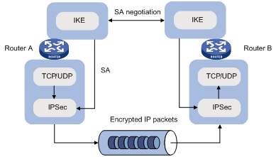
Figure 5 illustrates the relationship between IKE and IPsec:
· IKE is an application layer protocol using UDP and functions as the signaling protocol of IPsec.
· IKE negotiates SAs for IPsec and delivers negotiated parameters and generated keys to IPsec.
· IPsec uses the SAs set up through IKE negotiation for encryption and authentication of IP packets.
Protocols and standards
· RFC 2408, Internet Security Association and Key Management Protocol (ISAKMP)
· RFC 2409, The Internet Key Exchange (IKE)
· RFC 2412, The OAKLEY Key Determination Protocol
IKE configuration task list
Determine the following parameters prior to IKE configuration:
· The strength of the algorithms for IKE negotiation (the security protection level), including the identity authentication method, encryption algorithm, authentication algorithm, and DH group. Different algorithms provide different levels of protection. A stronger algorithm means more resistance to decryption of protected data but requires more resources. Generally, the longer the key, the stronger the algorithm.
· The pre-shared key or the PKI domain the certificate belongs to. For more information about PKI configuration, see "Configuring PKI."
To configure IKE:
|
Task |
Remarks |
|
Optional. |
|
|
Optional. Required if you want to specify an IKE proposal for an IKE peer to reference. |
|
|
Required. |
|
|
Optional. |
|
|
Optional. |
|
|
Optional. |
|
|
Optional. |
Configuring a name for the local security gateway
If the IKE negotiation peer uses the security gateway name as its ID to initiate IKE negotiation (the id-type name or id-type user-fqdn command is configured on the initiator), configure the ike local-name command in system view or the local-name command in IKE peer view on the local device. If you configure both commands, the name configured by in IKE peer view is used.
To configure a name for the local security gateway:
|
Step |
Command |
Remarks |
|
1. Enter system view. |
system-view |
N/A |
|
2. Configure a name for the local security gateway. |
ike local-name name |
Optional. By default, the device name is used as the name of the local security gateway. |
Configuring an IKE proposal
An IKE proposal defines a set of attributes describing how IKE negotiation should take place. You can create multiple IKE proposals with different preferences. The preference of an IKE proposal is represented by its sequence number. The lower the sequence number, the higher the preference.
Two peers must have at least one matching IKE proposal for successful IKE negotiation. During IKE negotiation, the initiator sends its IKE proposals to the peer, and the peer searches its own IKE proposals for a match. The search starts from the IKE proposal with the lowest sequence number and proceeds in the ascending order of sequence number until a match is found or all the IKE proposals are found mismatching. The matching IKE proposals are used to establish the secure tunnel.
The two matching IKE proposals have the same encryption algorithm, authentication method, authentication algorithm, and DH group. The SA lifetime takes the SA lifetime with a smaller value of the two.
By default, there is an IKE proposal, which has the lowest preference and uses the default encryption algorithm, authentication method, authentication algorithm, DH group, and ISAKMP SA lifetime.
To configure an IKE proposal:
|
Step |
Command |
Remarks |
|
1. Enter system view. |
system-view |
N/A |
|
2. Create an IKE proposal and enter its view. |
ike proposal proposal-number |
N/A |
|
3. Specify an encryption algorithm for the IKE proposal. |
encryption-algorithm aes-cbc [ key-length ] |
Optional. 128-bit AES in CBC mode by default. |
|
4. Specify an authentication method for the IKE proposal. |
authentication-method { pre-share | rsa-signature } |
Optional. Pre-shared key by default. |
|
5. Specify an authentication algorithm for the IKE proposal. |
authentication-algorithm sha |
Optional. SHA1 by default. |
|
6. Specify a DH group for key negotiation in phase 1. |
dh { group2 | group5 | group14 } |
Optional. The default DH group is group2 (the 1024-bit DH group). |
|
7. Set the ISAKMP SA lifetime for the IKE proposal. |
sa duration seconds |
Optional. 86400 seconds by default. Before an ISAKMP SA expires, IKE negotiates a new SA to replace it. DH calculation in IKE negotiation takes time, especially on low-end devices. To prevent SA updates from influencing normal communication, set the lifetime greater than 10 minutes. |
Configuring an IKE peer
For an IPsec policy that uses IKE, you must configure an IKE peer by performing the following tasks:
· Specify the IKE negotiation mode (main mode) for the local end to use in IKE negotiation phase 1. When acting as the IKE negotiation responder, the local end uses the IKE negotiation mode of the remote end.
· Specify the IKE proposals for the local end to use when acting as the IKE negotiation initiator. When acting as the responder, the local end uses the IKE proposals configured in system view for negotiation.
· Configure a pre-shared key for pre-shared key authentication or a PKI domain for digital signature authentication.
· Specify the ID type for the local end to use in IKE negotiation phase 1. With pre-shared key authentication, the ID type must be IP address for main mode IKE negotiation and can be IP address, FQDN, or user FQDN for aggressive mode IKE negotiation.
· Specify the name or IP address of the local security gateway. You perform this task only when you want to specify a special address, a loopback interface address, for example, as the local security gateway address.
· Specify the name or IP address of the remote security gateway. For the local end to initiate IKE negotiation, you must specify the name or IP address of the remote security gateway on the local end so the local end can find the remote end.
· Enable NAT traversal. If there is NAT gateway on the path for tunneling, you must configure NAT traversal at the two ends of the IPsec tunnel, because one end might use a public address while the other end uses a private address.
· Specify the DPD detector for the IKE peer.
To configure an IKE peer:
|
Step |
Command |
Remarks |
|
1. Enter system view. |
system-view |
N/A |
|
2. Create an IKE peer and enter IKE peer view. |
ike peer peer-name |
N/A |
|
3. Specify the IKE negotiation mode for phase 1. |
exchange-mode main |
Optional. The default is main. |
|
4. Specify the IKE proposals for the IKE peer to reference. |
proposal proposal-number&<1-6> |
Optional. By default, an IKE peer references no IKE proposals, and, when initiating IKE negotiation, it uses the IKE proposals configured in system view. |
|
5. Configure a pre-shared key for pre-shared key authentication or specify a PKI domain for digital signature authentication. |
· To configure a pre-shared key: · To specify a PKI domain: |
Configure either command according to the authentication method for the IKE proposal. |
|
6. Select the ID type for IKE negotiation phase 1. |
id-type { ip | name | user-fqdn } |
Optional. By default, the ID type is IP. |
|
7. Configure a name for the local security gateway. |
local-name name |
Optional. By default, no name is configured for the local security gateway in IKE peer view, and the security gateway name configured by using the ike local-name command is used. |
|
8. Specify the name of the remote security gateway. |
remote-name name |
Optional. The remote gateway name configured with remote-name command on the local gateway must be identical to the local name configured with the local-name command on the peer. |
|
9. Configure an IP address for the local gateway. |
local-address ip-address |
Optional. By default, it is the primary IP address of the interface referencing the security policy. |
|
10. Specify the IP addresses of the remote gateway. |
remote-address { hostname | low-ip-address [ high-ip-address ] } |
Optional. The remote IP address configured with the remote-address command on the local gateway must be identical to the local IP address configured with the local-address command on the peer. |
|
11. Enable the NAT traversal function for IPsec/IKE. |
nat traversal |
Optional. Required when a NAT gateway is present in the VPN tunnel constructed by IPsec/IKE. Disabled by default. |
|
12. Set the subnet types of the two ends. |
· Set the subnet type of the local end: · Set the subnet type of the peer end: |
Optional. The default subnet type is single-subnet. Use these two commands only when the device is working together with a NetScreen device. |
|
13. Apply a DPD detector to the IKE peer. |
dpd dpd-name |
Optional. No DPD detector is applied to an IKE peer by default. For more information about DPD configuration, see "Configuring a DPD detector." |
|
|
NOTE: After modifying the configuration of an IPsec IKE peer, execute the reset ipsec sa and reset ike sa commands to clear existing IPsec and IKE SAs. Otherwise, SA re-negotiation will fail. |
Setting keepalive timers
IKE maintains the link status of an ISAKMP SA by keepalive packets. Generally, if the peer is configured with the keepalive timeout, you must configure the keepalive packet transmission interval on the local end. If the peer receives no keepalive packet during the timeout interval, the ISAKMP SA is tagged with the TIMEOUT tag (if it does not have the tag), or deleted along with the IPsec SAs it negotiated (when it has the tag already).
The keepalive timeout configured at the local end must be longer than the keepalive interval configured at the remote end. Since it seldom occurs that more than three consecutive packets are lost on a network, the keepalive timeout can be configured to be three times of the keepalive interval.
To set the keepalive timers:
|
Step |
Command |
Remarks |
|
1. Enter system view. |
system-view |
N/A |
|
2. Set the ISAKMP SA keepalive interval. |
ike sa keepalive-timer interval seconds |
No keepalive packet is sent by default. |
|
3. Set the ISAKMP SA keepalive timeout. |
ike sa keepalive-timer timeout seconds |
No keepalive packet is sent by default. |
Setting the NAT keepalive timer
If IPsec traffic needs to pass through NAT security gateways, you must configure the NAT traversal function. If no packet travels across an IPsec tunnel in a certain period of time, the NAT mapping might get aged and be deleted, disabling the tunnel beyond the NAT gateway from transmitting data to the intended end. To prevent NAT mappings from being aged, an ISAKMP SA behind the NAT security gateway sends NAT keepalive packets to its peer at a certain interval to keep the NAT session alive.
To set the NAT keepalive timer:
|
Step |
Command |
Remarks |
|
1. Enter system view. |
system-view |
N/A |
|
2. Set the NAT keepalive interval. |
ike sa nat-keepalive-timer interval seconds |
20 seconds by default. |
Configuring a DPD detector
DPD irregularly detects dead IKE peers. It works as follows:
1. When the local end sends an IPsec packet, it checks the time the last IPsec packet was received from the peer.
2. If the time interval exceeds the DPD interval, it sends a DPD hello to the peer.
3. If the local end receives no DPD acknowledgement within the DPD packet retransmission interval, it retransmits the DPD hello.
4. If the local end still receives no DPD acknowledgement after having made the maximum number of retransmission attempts (two by default), it considers the peer already dead, and clears the IKE SA and the IPsec SAs based on the IKE SA.
DPD enables an IKE entity to check the liveliness of its peer only when necessary. It generates less traffic than the keepalive mechanism, which exchanges messages periodically.
To configure a DPD detector:
|
Step |
Command |
Remarks |
|
1. Enter system view. |
system-view |
N/A |
|
2. Create a DPD detector and enter its view. |
ike dpd dpd-name |
N/A |
|
3. Set the DPD interval. |
interval-time interval-time |
Optional. 10 seconds by default. |
|
4. Set the DPD packet retransmission interval. |
time-out time-out |
Optional. 5 seconds by default. |
Disabling next payload field checking
The Next payload field is in the generic payload header of the last payload of the IKE negotiation message (the message comprises multiple payloads). According to the protocol, this field must be 0 if the payload is the last payload of the packet. However, it might be set to other values on some brands of devices. For interoperability, disable the checking of this field.
To disable Next payload field checking:
|
Step |
Command |
Remark |
|
1. Enter system view. |
system-view |
N/A |
|
2. Disable Next payload field checking. |
ike next-payload check disabled |
Enabled by default. |
Displaying and maintaining IKE
|
Task |
Command |
Remarks |
|
Display IKE DPD information. |
display ike dpd [ dpd-name ] [ | { begin | exclude | include } regular-expression ] |
Available in any view. |
|
Display IKE peer information. |
display ike peer [ peer-name ] [ | { begin | exclude | include } regular-expression ] |
Available in any view. |
|
Display IKE SA information. |
display ike sa [ verbose [ connection-id connection-id | remote-address remote-address ] ] [ | { begin | exclude | include } regular-expression ] |
Available in any view. |
|
Display IKE proposal information. |
display ike proposal [ | { begin | exclude | include } regular-expression ] |
Available in any view. |
|
Clear SAs established by IKE. |
reset ike sa [ connection-id ] |
Available in user view. |
IKE configuration example
This configuration example is only suitable for the switches operating in FIPS mode.
Network requirements
As shown in Figure 6, an IPsec tunnel is established through IKE negotiation between Switch A and Switch B to allow secure communication between them.
Switch A is configured with an IKE proposal using the sequence number of 10 and the authentication algorithm of SHA1. Switch B has only the default IKE proposal.
The two switches use the pre-shared key authentication method.
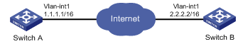
Configuration procedure
1. Make sure the route between Switch A and Switch B is reachable.
2. Configure Switch A:
# Assign an IP address to VLAN-interface 1.
<SwitchA> system-view
[SwitchA] interface vlan-interface 1
[SwitchA-vlan-interface1] ip address 1.1.1.1 255.255.255.0
[SwitchA-vlan-interface1] quit
# Define an ACL to identify data flows between Switch A and Switch B.
[SwitchA] acl number 3101
[SwitchA-acl-adv-3101] rule 0 permit ip source 1.1.1.1 0 destination 2.2.2.2 0
[SwitchA-acl-adv-3101] rule 1 permit ip source 2.2.2.2 0 destination 1.1.1.1 0
[SwitchA-acl-adv-3101] quit
# Create IPsec proposal tran1.
[SwitchA] ipsec proposal tran1
# Set the packet encapsulation mode to tunnel.
[SwitchA-ipsec-proposal-tran1] encapsulation-mode tunnel
# Specify ESP as the security protocol.
[SwitchA-ipsec-proposal-tran1] transform esp
# Specify AES 128 as the encryption algorithm and SHA1-HMAC-96 as the authentication algorithm.
[SwitchA-ipsec-proposal-tran1] esp encryption-algorithm aes 128
[SwitchA-ipsec-proposal-tran1] esp authentication-algorithm sha1
[SwitchA-ipsec-proposal-tran1] quit
# Create IKE proposal 10.
[SwitchA] ike proposal 10
# Specify SHA1 as the authentication algorithm.
[SwitchA-ike-proposal-10] authentication-algorithm sha
# Specify pre-share as the authentication method.
[SwitchA-ike-proposal-10] authentication-method pre-share
# Set the IKE SA lifetime to 5000 seconds.
[SwitchA-ike-proposal-10] sa duration 5000
[SwitchA-ike-proposal-10] quit
# Create IKE peer peer.
[SwitchA] ike peer peer
# Reference IKE proposal 10.
[SwitchA-ike-peer-peer] proposal 10
# Set the pre-shared key.
[SwitchA-ike-peer-peer] pre-shared-key Ab12<><>
# Specify the IP address of the peer security gateway.
[SwitchA-ike-peer-peer] remote-address 2.2.2.2
[SwitchA-ike-peer-peer] quit
# Create an IPsec policy that uses IKE.
[SwitchA] ipsec policy map1 10 isakmp
# Reference IPsec proposal tran1.
[SwitchA-ipsec-policy-isakmp-map1-10] proposal tran1
# Reference ACL 3101 to identify the protected traffic.
[SwitchA-ipsec-policy-isakmp-map1-10] security acl 3101
# Reference IKE peer peer.
[SwitchA-ipsec-policy-isakmp-map1-10] ike-peer peer
[SwitchA-ipsec-policy-isakmp-map1-10] quit
# Apply the IPsec policy group to VLAN-interface 1.
[SwitchA] interface vlan-interface 1
[SwitchA-Vlan-interface1] ipsec policy map1
3. Configure Switch B:
# Assign an IP address to VLAN-interface 1.
<SwitchB> system-view
[SwitchB] interface Vlan-interface1
[SwitchB-Vlan-interface1] ip address 2.2.2.2 255.255.255.0
[SwitchB-Vlan-interface1] quit
# Define an ACL to identify data flows between Switch B and Switch A.
[SwitchB] acl number 3101
[SwitchB-acl-adv-3101] rule 0 permit ip source 2.2.2.2 0 destination 1.1.1.0 0
[SwitchB-acl-adv-3101] rule 1 permit ip source 1.1.1.1 0 destination 2.2.2.2 0
[SwitchB-acl-adv-3101] quit
# Create IPsec proposal tran1.
[SwitchB] ipsec proposal tran1
# Set the packet encapsulation mode to tunnel.
[SwitchB-ipsec-proposal-tran1] encapsulation-mode tunnel
# Specify ESP as the security protocol.
[SwitchB-ipsec-proposal-tran1] transform esp
# Specify AES 128 as the encryption algorithm and SHA1-HMAC-96 as the authentication algorithm.
[SwitchB-ipsec-proposal-tran1] esp encryption-algorithm aes 128
[SwitchB-ipsec-proposal-tran1] esp authentication-algorithm sha1
[SwitchB-ipsec-proposal-tran1] quit
# Create IKE proposal 10.
[SwitchB] ike proposal 10
# Specify SHA1 as the authentication algorithm.
[SwitchB-ike-proposal-10] authentication-algorithm sha
# Specify pre-share as the authentication method.
[SwitchB-ike-proposal-10] authentication-method pre-share
# Set the IKE SA lifetime to 5000 seconds.
[SwitchB-ike-proposal-10] sa duration 5000
[SwitchB-ike-proposal-10] quit
# Create IKE peer peer.
[SwitchB] ike peer peer
# Reference IKE proposal 10.
[SwitchB-ike-peer-peer] proposal 10
# Set the pre-shared key.
[SwitchB-ike-peer-peer] pre-shared-key Ab12<><>
# Specify the IP address of the peer security gateway.
[SwitchB-ike-peer-peer] remote-address 1.1.1.1
[SwitchB-ike-peer-peer] quit
# Create an IPsec policy that uses IKE.
[SwitchB] ipsec policy use1 10 isakmp
# Reference IPsec proposal tran1.
[SwitchB-ipsec-policy-isakmp-use1-10] proposal tran1
# Reference ACL 3101 to identify the protected traffic.
[SwitchB-ipsec-policy-isakmp-use1-10] security acl 3101
# Reference IKE peer peer.
[SwitchB-ipsec-policy-isakmp-use1-10] ike-peer peer
[SwitchB-ipsec-policy-isakmp-use1-10] quit
# Apply the IPsec policy group to VLAN-interface 1.
[SwitchB] interface Vlan-interface1
[SwitchB-Vlan-interface1] ipsec policy use1
Verifying the configuration
After the configuration, IKE negotiation will be triggered when there is traffic between Switch A and Switch B. During the IKE negotiation, the proposals are matched from the one with the highest priority. Lifetime is not required to be matched, and the two switches negotiate a lifetime.
Troubleshooting IKE
When you configure parameters to establish an IPsec tunnel, enable IKE error debugging to locate configuration problems:
<Switch> debugging ike error
Invalid user ID
Symptom
A user ID is invalid.
Analysis
In IPsec, user IDs identify IPsec tunnels for different data flows. In the H3C implementation of IPsec, a user ID comprises an IP address and a username.
The following is the debugging information:
got NOTIFY of type INVALID_ID_INFORMATION
Or
drop message from A.B.C.D due to notification type INVALID_ID_INFORMATION
Solution
Verify that the ACLs in the IPsec policies configured on the interfaces at both ends are correct and mirror each other. For more information about ACL configuration, see "Configuring an ACL."
Proposal mismatch
Symptom
The proposals mismatch.
Analysis
The following is the debugging information:
got NOTIFY of type NO_PROPOSAL_CHOSEN
Or
drop message from A.B.C.D due to notification type NO_PROPOSAL_CHOSEN
The two parties in the negotiation have no matched proposals.
Solution
For the negotiation in phase 1, look up the IKE proposals for a match.
For the negotiation in phase 2, verify that the parameters of the IPsec policies applied on the interfaces are matched, and that the referred IPsec proposals have a match in protocol, encryption and authentication algorithms.
Failing to establish an IPsec tunnel
Symptom
The expected IPsec tunnel cannot be established.
Analysis
Sometimes this might happen if an IPsec tunnel cannot be established or there is no way to communicate in the presence of an IPsec tunnel in an unstable network.
If ACLs of both parties are configured correctly, and proposals are also matched, the problem is usually caused by the reboot of one switch after the IPsec tunnel is established.
Solution
· Use the display ike sa command to verify that both parties have established an SA in phase 1.
· Use the display ipsec sa policy command to verify that the IPsec policy on the interface has established IPsec SA.
· If the two commands show that one party has an SA but the other does not, use the reset ipsec sa command to clear the IPsec SA that has no corresponding SA, use the reset ike sa command to clear the IKE SA that has no corresponding IKE SA, and trigger SA re-negotiation.
ACL configuration error
Symptom
ACL configuration error results in data flow blockage.
Analysis
When multiple devices create different IPsec tunnels early or late, a device might have multiple peers. If the device is not configured with ACL rule, the peers send packets to it to set up different IPsec tunnels in different protection granularity respectively. As the priorities of IPsec tunnels are determined by the order they are established, a device cannot interoperate with other peers in fine granularity when its outbound packets are first matched with an IPsec tunnel in coarse granularity.
Solution
When a device has multiple peers, configure ACLs on the device to distinguish different data flows and try to avoid configuring overlapping ACL rules for different peers. If it is unavoidable, the subrules in fine granularity should be configured with higher preferences.