- Table of Contents
-
- 11-Security Configuration Guide
- 00-Preface
- 01-Security Overview
- 02-AAA Configuration
- 03-802.1X Configuration
- 04-MAC Authentication Configuration
- 05-Portal Configuration
- 06-Password Control Configuration
- 07-Public Key Configuration
- 08-IPsec Configuration
- 09-SSH Configuration
- 10-Blacklist Configuration
- 11-TCP and ICMP Attack Protection Configuration
- 12-IP Source Guard Configuration
- 13-ARP Attack Protection Configuration
- 14-ND Attack Defense Configuration
- 15-URPF Configuration
- 16-PKI Configuration
- 17-SSL Configuration
- 18-FIPS Configuration
- 19-Attack Detection and Protection Configuration
- Related Documents
-
| Title | Size | Download |
|---|---|---|
| 13-ARP Attack Protection Configuration | 219.53 KB |
Contents
Configuring ARP attack protection·
ARP attack protection configuration task list
Configuring ARP defense against IP packet attacks
Configuring ARP source suppression
Enabling ARP blackhole routing
Displaying and maintaining ARP defense against IP packet attacks
Configuring ARP packet rate limit
Configuring source MAC-based ARP attack detection
Displaying and maintaining source MAC-based ARP attack detection
Configuring ARP packet source MAC address consistency check
Configuring ARP active acknowledgement
Authorized ARP configuration example (on a DHCP server)
Authorized ARP configuration example (on a DHCP relay agent)
Configuring ARP detection based on specified objects
Configuring ARP restricted forwarding
Displaying and maintaining ARP detection
ARP detection configuration example 1
ARP detection configuration example 2
ARP restricted forwarding configuration example
Overview
Although ARP is easy to implement, it provides no security mechanism and thus is prone to network attacks. An attacker might send:
· ARP packets by acting as a trusted user or gateway, so that the receiving switch obtains incorrect ARP entries.
· A large number of IP packets with unreachable destinations. As a result, the receiving switch continuously resolves destination IP addresses and thus its CPU is overloaded.
· A large number of ARP packets to overload the CPU of the receiving device.
For more information about ARP attack features and types, see ARP Attack Protection Technology White Paper.
ARP attacks and viruses are threatening LAN security. This chapter introduces switch features to detect and prevent such attacks.
ARP attack protection configuration task list
|
Task |
Remarks |
||
|
Flood prevention |
Optional. Configure this function on gateways (recommended). |
||
|
Optional. Configure this function on gateways (recommended). |
|||
|
Optional. Configure this function on access devices (recommended). |
|||
|
Optional. Configure this function on gateways (recommended). |
|||
|
User and gateway spoofing prevention |
Optional. Configure this function on gateways (recommended). |
||
|
Optional. Configure this function on gateways (recommended). |
|||
|
Optional. Configure this function on gateways (recommended). |
|||
|
Optional. Configure this function on access devices (recommended). |
|||
Configuring ARP defense against IP packet attacks
Introduction
If a switch receives a large number of IP packets from a host to unreachable destinations, the following situations can occur:
· The switch sends a large number of ARP requests to the destination subnets, and thus the load of the destination subnets increases.
· The switch keeps trying to resolve destination IP addresses, increasing the load of the CPU.
To protect the switch from IP packet attacks, you can enable the ARP source suppression function or ARP blackhole routing function.
If the packets have the same source address, you can enable the ARP source suppression function. With the function enabled, you can set a threshold for the number of ARP requests that a sending host can trigger in 5 seconds with packets with unresolvable destination IP addresses. When the number of ARP requests exceeds that threshold, the switch suppresses the sending host from triggering any ARP requests in the following 5 seconds.
If the packets have various source addresses, you can enable the ARP blackhole routing function. After receiving an IP packet whose destination IP address cannot be resolved by ARP, the switch with this function enabled immediately creates a blackhole route and simply drops all packets matching the route during the aging time of the blackhole route.
Configuring ARP source suppression
|
Command |
Remarks |
|
|
1. Enter system view. |
system-view |
N/A |
|
2. Enable ARP source suppression. |
arp source-suppression enable |
Disabled by default. |
|
3. Set the maximum number of packets with the same source IP address but unresolvable destination IP addresses that the switch can receive in 5 consecutive seconds. |
arp source-suppression limit limit-value |
Optional. 10 by default. |
Enabling ARP blackhole routing
|
Step |
Command |
Remarks |
|
1. Enter system view. |
system-view |
N/A |
|
2. Enable ARP blackhole routing. |
arp resolving-route enable |
Optional. Enabled by default. |
Displaying and maintaining ARP defense against IP packet attacks
|
Task |
Command |
Remarks |
|
Display the ARP source suppression configuration information. |
display arp source-suppression [ | { begin | exclude | include } regular-expression ] |
Available in any view. |
Configuring ARP packet rate limit
Introduction
The ARP packet rate limit feature allows you to limit the rate of ARP packets to be delivered to the CPU on a switch. For example, if an attacker sends a large number of ARP packets to an ARP detection enabled switch, the CPU of the switch might become overloaded because all the ARP packets are redirected to the CPU for checking. As a result, the switch fails to deliver other functions correctly or even crashes. To solve this problem, you can configure ARP packet rate limit.
H3C recommends that you configure this feature after the ARP detection feature is configured, or use this feature to prevent ARP flood attacks.
Configuration procedure
To configure ARP packet rate limit:
|
Step |
Command |
Remarks |
|
1. Enter system view. |
system-view |
N/A |
|
2. Enter Layer 2 Ethernet interface/Layer 2 aggregate interface view. |
interface interface-type interface-number |
N/A |
|
3. Configure ARP packet rate limit. |
arp rate-limit { disable | rate pps drop } |
By default, ARP packet rate limit is disabled, and the ARP packet rate is in the range of 10 to 5000. |
Configuring source MAC-based ARP attack detection
This feature checks the number of ARP packets received from the same MAC address within 5 seconds against a specific threshold. If the threshold is exceeded, the device adds the MAC address in an ARP attack entry. Before the entry is aged out, the device handles the attack by using either of the following methods:
· Monitor—Only generates log messages.
· Filter—Generates log messages and filters out subsequent ARP packets from that MAC address.
You can exclude the MAC addresses of some gateways and servers from detection. This feature does not inspect ARP packets from those devices even if they are attackers.
Only the ARP packets delivered to the CPU are checked.
To configure source MAC-based ARP attack detection:
|
Step |
Command |
Remarks |
|
1. Enter system view. |
system-view |
N/A |
|
2. Enable source MAC-based ARP attack detection and specify the handling method. |
arp anti-attack source-mac { filter | monitor } |
Disabled by default. |
|
3. Configure the threshold. |
arp anti-attack source-mac threshold threshold-value |
Optional. 150 by default. |
|
4. Configure the age time for ARP attack entries. |
arp anti-attack source-mac aging-time time |
Optional. 300 seconds by default. |
|
5. Exclude specified MAC addresses from this detection. |
arp anti-attack source-mac exclude-mac mac-address&<1-n> |
Optional. No MAC address is excluded by default. The maximum value for n is 64. |
|
|
NOTE: After an ARP attack detection entry expires, ARP packets sourced from the MAC address in the entry can be processed correctly. |
Displaying and maintaining source MAC-based ARP attack detection
|
Task |
Command |
Remarks |
|
Display attacking entries detected (in standalone mode). |
display arp anti-attack source-mac { slot slot-number | interface interface-type interface-number } [ | { begin | exclude | include } regular-expression ] |
Available in any view. |
|
Display attacking entries detected (in IRF mode). |
display arp anti-attack source-mac { chassis chassis-number slot slot-number | interface interface-type interface-number } [ | { begin | exclude | include } regular-expression ] |
Available in any view. |
Configuring ARP packet source MAC address consistency check
Introduction
The ARP packet source MAC address consistency check feature enables a gateway device to filter out ARP packets that have a different source MAC address in the Ethernet header from the sender MAC address in the message, so that the gateway device can learn correct ARP entries.
Configuration procedure
To enable ARP packet source MAC address consistency check:
|
Step |
Command |
Remarks |
|
1. Enter system view. |
system-view |
N/A |
|
2. Enable ARP packet source MAC address consistency check. |
arp anti-attack valid-check enable |
Disabled by default. |
|
|
NOTE: Disable ARP packet source MAC address consistency check if cluster severs are used for transparent transmission or the switch needs to process the ARP packets from cluster servers. |
Configuring ARP active acknowledgement
Introduction
Typically, the ARP active acknowledgement feature is configured on gateway devices to identify invalid ARP packets.
ARP active acknowledgement works before the gateway creates or modifies an ARP entry to avoid generating any incorrect ARP entry. For more information about its working mechanism, see ARP Attack Protection Technology White Paper.
Configuration procedure
To configure ARP active acknowledgement:
|
Step |
Command |
Remarks |
|
1. Enter system view. |
system-view |
N/A |
|
2. Enable the ARP active acknowledgement function. |
arp anti-attack active-ack enable |
Disabled by default. |
Configuring authorized ARP
This feature is only supported on Ethernet interfaces that are operating in Layer 3 mode. For more information about the operating mode of Ethernet interfaces, see Interface Configuration Guide.
Introduction
Authorized ARP entries are generated based on the DHCP clients’ address leases on the DHCP server or dynamic bindings on the DHCP relay agent. For more information about the DHCP server and DHCP relay agent, see Layer 3—IP Services Configuration Guide.
After enabled with authorized ARP, the interface is disabled from learning dynamic ARP entries to prevent attacks from unauthorized clients that send packets using other clients’ IP or MAC addresses, and to allow only authorized clients to access network resources. Thus network security is enhanced.
Static ARP entries can overwrite authorized ARP entries, and authorized ARP entries can overwrite dynamic ARP entries. But authorized ARP entries cannot overwrite static ARP entries, and dynamic ARP entries cannot overwrite authorized ARP entries.
Configuration procedure
To enable authorized ARP:
|
Step |
Command |
Remarks |
|
1. Enter system view. |
system-view |
N/A |
|
2. Enter interface view. |
interface interface-type interface-number |
N/A |
|
3. Configure the Ethernet interface to operate in Layer 3 mode. |
port link-mode route |
For more information about the operating mode of Ethernet interfaces, see Interface Configuration Guide. |
|
4. Configure the DHCP server (or DHCP relay agent) to support authorized ARP. |
dhcp update arp |
Not configured by default. |
|
5. Enable authorized ARP on the interface. |
arp authorized enable |
Not enabled by default. |
Authorized ARP configuration example (on a DHCP server)
|
|
IMPORTANT: By default, Ethernet, VLAN, and aggregate interfaces are down. To configure such an interface, bring the interface up by executing the undo shutdown command. |
Network requirements
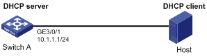
As shown in Figure 1, Switch A acts as a DHCP server with an IP address pool of 10.1.1.0/24. Enable authorized ARP on GigabitEthernet 3/0/1 of Switch A. The host is a DHCP client that obtains IP address 10.1.1.2/24 from the DHCP server.
Configuration procedure
1. Configure Switch A:
# Configure GigabitEthernet 3/0/1 to operate in Layer 3 mode.
<SwitchA> system-view
[SwitchA] interface GigabitEthernet 3/0/1
[SwitchA-GigabitEthernet3/0/1] port link-mode route
# Configure the IP address of GigabitEthernet 3/0/1.
[SwitchA-GigabitEthernet3/0/1] ip address 10.1.1.1 24
[SwitchA-GigabitEthernet3/0/1] quit
# Configure DHCP.
[SwitchA] dhcp enable
[SwitchA] dhcp server ip-pool 1
[SwitchA-dhcp-pool-1] network 10.1.1.0 mask 255.255.255.0
[SwitchA-dhcp-pool-1] quit
# Enter Layer 3 Ethernet interface view.
[SwitchA] interface GigabitEthernet 3/0/1
# Configure the DHCP server to support authorized ARP.
[SwitchA-GigabitEthernet3/0/1] dhcp update arp
# Enable authorized ARP.
[SwitchA-GigabitEthernet3/0/1] arp authorized enable
[SwitchA-GigabitEthernet3/0/1] quit
# Configure the aging time for authorized ARP entries.
[SwitchA-GigabitEthernet3/0/1] arp authorized time-out 120
[SwitchA-GigabitEthernet3/0/1] quit
2. After the host obtains an IP address from Switch A, display the authorized ARP entry information on Switch A.
[SwitchA] display arp all
Type: S-Static D-Dynamic A-Authorized M-Multiport
IP Address MAC Address VLAN ID Interface Aging Type
10.1.1.2 0012-3f86-e94c N/A GE3/0/1 2 A
The output shows that IP address 10.1.1.2 has been assigned to the host.
After that, the host must use the IP address and MAC address that are consistent with those in the authorized ARP entry to communicate with Switch A. Otherwise, the communication fails. Thus the client validity is ensured.
Authorized ARP configuration example (on a DHCP relay agent)
Network requirements
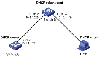
As shown in Figure 2, Switch A acts as a DHCP server with an IP address pool of 10.10.1.0/24. Switch B is a DHCP relay agent, which conveys the IP address from the DHCP server to the DHCP client (Host). Enable authorized ARP on GigabitEthernet 3/0/2 of Switch B.
Configuration procedure
1. Configure Switch A:
# Configure GigabitEthernet 3/0/1 to operate in Layer 3 mode.
<SwitchA> system-view
[SwitchA] interface GigabitEthernet 3/0/1
[SwitchA-GigabitEthernet3/0/1] port link-mode route
# Configure the IP address of GigabitEthernet 3/0/1.
[SwitchA-GigabitEthernet3/0/1] ip address 10.1.1.1 24
[SwitchA-GigabitEthernet3/0/1] quit
# Configure DHCP.
[SwitchA] dhcp enable
[SwitchA] dhcp server ip-pool 1
[SwitchA-dhcp-pool-1] network 10.10.1.0 mask 255.255.255.0
[SwitchA-dhcp-pool-1] gateway-list 10.10.1.1
[SwitchA-dhcp-pool-1] quit
[SwitchA] ip route-static 10.10.1.0 24 10.1.1.2
2. Configure Switch B:
# Enable DHCP.
<SwitchB> system-view
[SwitchB] dhcp enable
# Configure GigabitEthernet 3/0/1 to operate in Layer 3 mode.
[SwitchB] interface GigabitEthernet 3/0/1
[SwitchB-GigabitEthernet3/0/1] port link-mode route
# Configure the IP addresses of GigabitEthernet 3/0/1 and GigabitEthernet 3/0/2.
[SwitchB-GigabitEthernet3/0/1] ip address 10.1.1.2 24
[SwitchB-GigabitEthernet3/0/1] quit
[SwitchB] interface GigabitEthernet 3/0/2
[SwitchB-GigabitEthernet3/0/2] port link-mode route
[SwitchB-GigabitEthernet3/0/2] ip address 10.10.1.1 24
# Enable DHCP relay agent on GigabitEthernet 3/0/2.
[SwitchB-GigabitEthernet3/0/2] dhcp select relay
[SwitchB-GigabitEthernet3/0/2] quit
# Add the DHCP server 10.1.1.1 to DHCP server group 1.
[SwitchB] dhcp relay server-group 1 ip 10.1.1.1
# Correlate GigabitEthernet 3/0/2 to DHCP server group 1.
[SwitchB] interface GigabitEthernet 3/0/2
[SwitchB-GigabitEthernet3/0/2] dhcp relay server-select 1
# Configure the DHCP server to support authorized ARP.
[SwitchB-GigabitEthernet3/0/2] dhcp update arp
# Enable authorized ARP.
[SwitchB-GigabitEthernet3/0/2] arp authorized enable
[SwitchB-GigabitEthernet3/0/2] quit
3. After Host obtains the IP address from Switch A, display the authorized ARP information on Switch B.
[SwitchB] display arp all
Type: S-Static D-Dynamic A-Authorized M-Multiport
IP Address MAC Address VLAN ID Interface Aging Type
10.10.1.2 0012-3f86-e94c N/A GE3/0/2 2 A
The output shows that Switch A assigned IP address 10.10.1.2 to Host.
After that, Host must use the IP address and MAC address that are consistent with those in the authorized ARP entry to communicate with Switch B. Otherwise, the communication fails. Thus the client validity is ensured.
Configuring ARP detection
Introduction
The ARP detection feature is mainly configured on an access device to allow only the ARP packets of authorized clients to be forwarded and prevent user spoofing and gateway spoofing.
ARP detection includes ARP detection based on static IP source guard binding entries/DHCP snooping entries/802.1X security entries/OUI MAC addresses, ARP detection based on specified objects, and ARP restricted forwarding.
If both the ARP detection based on specified objects and the ARP detection based on static IP source guard binding entries/DHCP snooping entries/802.1X security entries/OUI MAC addresses are enabled, the former one applies first, and then the latter applies.
Enabling ARP detection based on static IP source guard binding entries/DHCP snooping entries/802.1x security entries/OUI MAC addresses
With this feature enabled, the switch compares the sender IP and MAC addresses of an ARP packet received from the VLAN against the static IP source guard binding entries, DHCP snooping entries, 802.1X security entries, or OUI MAC addresses to prevent spoofing.
After you enable this feature for a VLAN:
1. Upon receiving an ARP packet from an ARP untrusted port, the switch compares the sender IP and MAC addresses of the ARP packet against the static IP source guard binding entries. If a match is found, the ARP packet is considered valid and is forwarded. If an entry with a matching IP address but an unmatched MAC address is found, the ARP packet is considered invalid and is discarded. If no entry with a matching IP address is found, the switch compares the ARP packet’s sender IP and MAC addresses against the DHCP snooping entries, 802.1X security entries, and OUI MAC addresses.
2. If a match is found in any of the entries, the ARP packet is considered valid and is forwarded. ARP detection based on OUI MAC addresses refers to that if the sender MAC address of the received ARP packet is an OUI MAC address and voice VLAN is enabled, the packet is considered valid.
3. If no match is found, the ARP packet is considered invalid and is discarded.
4. Upon receiving an ARP packet from an ARP trusted port, the switch does not check the ARP packet.
Configuration guidelines
· Static IP source guard binding entries are created by using the ip source binding command. For more information, see "Configuring IP source guard."
· Dynamic DHCP snooping entries are automatically generated through the DHCP snooping function. For more information, see Layer 3—IP Services Configuration Guide.
· 802.1X security entries are generated in this case. After a client passes 802.1X authentication and uploads its IP address to an ARP detection enabled device, the device automatically generates an 802.1X security entry. Therefore, the 802.1X client must be able to upload its IP address to the device. For more information, see "Configuring 802.1X."
· For more information about voice VLANs and QUI MAC addresses, see Layer 2—LAN Switching Configuration Guide.
Configuration procedure
To enable ARP detection for a VLAN and specify a trusted port:
|
Step |
Command |
Remarks |
|
1. Enter system view. |
system-view |
N/A |
|
2. Enter VLAN view. |
vlan vlan-id |
N/A |
|
3. Enable ARP detection for the VLAN. |
arp detection enable |
Disabled by default. ARP detection based on static IP source guard binding entries/DHCP snooping entries/802.1X security entries/OUI MAC addresses is disabled by default. |
|
4. Return to system view. |
quit |
N/A |
|
5. Enter Layer 2 Ethernet interface view or Layer 2 aggregate interface view. |
interface interface-type interface-number |
N/A |
|
6. Configure the port as a trusted port on which ARP detection does not apply. |
arp detection trust |
Optional. The port is an untrusted port by default. |
When configuring this feature, you need to configure ARP detection based on at least static IP source guard binding entries, DHCP snooping entries, or 802.1X security entries. Otherwise, all ARP packets received from an ARP untrusted port will be discarded, except the ARP packets with an OUI MAC address as the sender MAC address when voice VLAN is enabled.
When configuring an IP Source guard binding entry, you need to specify the VLAN. Otherwise, no ARP packet will pass the ARP detection based on static IP source guard binding entries.
Configuring ARP detection based on specified objects
With this feature configured, the switch permits the ARP packets received from an ARP trusted port, and checks the ARP packets received from an ARP untrusted port. You can specify objects in the ARP packets to be checked. The objects involve:
· src-mac—Checks whether the sender MAC address of an ARP packet is identical to the source MAC address in the Ethernet header. If they are identical, the packet is forwarded. Otherwise, the packet is discarded.
· dst-mac—Checks the target MAC address of ARP replies. If the target MAC address is all-zero, all-one, or inconsistent with the destination MAC address in the Ethernet header, the packet is considered invalid and discarded.
· ip—Checks the sender and target IP addresses in an ARP packet. The all-zero, all-one or multicast IP addresses are considered invalid and the corresponding packets are discarded. With this object specified, the sender and target IP addresses of ARP replies, and the source IP address of ARP requests are checked.
To configure ARP detection based on specified objects:
|
Step |
Command |
Remarks |
|
1. Enter system view. |
system-view |
N/A |
|
2. Enter VLAN view. |
vlan vlan-id |
N/A |
|
3. Enable ARP detection for the VLAN. |
arp detection enable |
Disabled by default. |
|
4. Return to system view. |
quit |
N/A |
|
5. Specify the objects to be checked. |
arp detection validate { dst-mac | ip | src-mac } * |
N/A |
|
6. Enter Ethernet interface view. |
interface interface-type interface-number |
N/A |
|
7. Configure the port as a trusted port on which ARP detection does not apply. |
arp detection trust |
Optional. The port is an untrusted port by default. |
Configuring ARP restricted forwarding
ARP restricted forwarding controls the forwarding of ARP packets that are received on untrusted ports and have passed ARP detection as follows:
· If the packets are ARP requests, they are forwarded through the ARP-trusted ports.
· If the packets are ARP responses, they are forwarded according to their destination MAC address. If no match is found in the MAC address table, they are forwarded through the ARP-trusted ports.
Before performing the following configuration, make sure you have configured the arp detection enable command.
To enable ARP restricted forwarding:
|
Step |
Command |
Remarks |
|
1. Enter system view. |
system-view |
N/A |
|
2. Enter VLAN view. |
vlan vlan-id |
N/A |
|
3. Enable ARP restricted forwarding. |
arp restricted-forwarding enable |
Disabled by default. |
Displaying and maintaining ARP detection
|
Task |
Command |
Remarks |
|
Display the VLANs enabled with ARP detection. |
display arp detection [ | { begin | exclude | include } regular-expression ] |
Available in any view. |
|
Display the ARP detection statistics. |
display arp detection statistics [ interface interface-type interface-number ] [ | { begin | exclude | include } regular-expression ] |
Available in any view. |
|
Clear the ARP detection statistics. |
reset arp detection statistics [ interface interface-type interface-number ] |
Available in user view. |
ARP detection configuration example 1
Network requirements
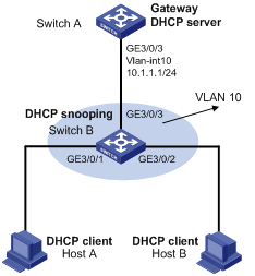
As shown in Figure 3, configure Switch A as a DHCP server and enable 802.1X on Switch B. Enable ARP detection for VLAN 10 to allow only packets from valid clients to pass. Configure Host A and Host B as local 802.1X access users.
Configuration procedure
1. Add all the ports on Switch B into VLAN 10, and configure the IP address of VLAN-interface 10 on Switch A. (Details not shown.)
2. Configure DHCP address pool 0 on Switch A as a DHCP server.
<SwitchA> system-view
[SwitchA] dhcp enable
[SwitchA] dhcp server ip-pool 0
[SwitchA-dhcp-pool-0] network 10.1.1.0 mask 255.255.255.0
3. Configure Host A and Host B as 802.1X clients (details not shown) and configure them to upload IP addresses for ARP detection.
4. Configure Switch B:
# Enable the 802.1X function.
<SwitchB> system-view
[SwitchB] dot1x
[SwitchB] interface GigabitEthernet 3/0/1
[SwitchB-GigabitEthernet3/0/1] dot1x
[SwitchB-GigabitEthernet3/0/1] quit
[SwitchB] interface GigabitEthernet 3/0/2
[SwitchB-GigabitEthernet3/0/2] dot1x
[SwitchB-GigabitEthernet3/0/2] quit
# Add local access user test.
[SwitchB] local-user test
[SwitchB-luser-test] service-type lan-access
[SwitchB-luser-test] password simple test
[SwitchB-luser-test] quit
# Enable ARP detection for VLAN 10.
[SwitchB] vlan 10
[SwitchB-vlan10] arp detection enable
# Configure the upstream port as a trusted port and the downstream ports as untrusted ports (a port is an untrusted port by default).
[SwitchB-vlan10] interface GigabitEthernet 3/0/3
[SwitchB-GigabitEthernet3/0/3] arp detection trust
[SwitchB-GigabitEthernet3/0/3] quit
After the preceding configurations are complete, when ARP packets arrive at interfaces GigabitEthernet 3/0/1 and GigabitEthernet 3/0/2, they are checked against 802.1X security entries.
ARP detection configuration example 2
|
|
IMPORTANT: By default, Ethernet, VLAN, and aggregate interfaces are down. To configure such an interface, bring the interface up by executing the undo shutdown command. |
Network requirements
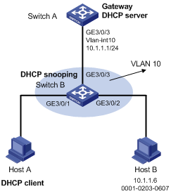
As shown in Figure 4, configure Switch A as a DHCP server and enable DHCP snooping on Switch B. Configure Host A as a DHCP client. Configure Host B whose IP address is 10.1.1.6 and MAC address is 0001-0203-0607. Enable ARP detection for VLAN 10 to allow only packets from valid clients or hosts to pass.
Configuration procedure
1. Add all the ports on Switch B to VLAN 10, and configure the IP address of VLAN-interface 10 on Switch A. (Details not shown.)
2. Configure DHCP address pool 0 on Switch A as a DHCP server.
<SwitchA> system-view
[SwitchA] dhcp enable
[SwitchA] dhcp server ip-pool 0
[SwitchA-dhcp-pool-0] network 10.1.1.0 mask 255.255.255.0
3. Configure Host A as DHCP client, and Host B as user. (Details not shown.)
4. Configure Switch B:
# Enable DHCP snooping.
<SwitchB> system-view
[SwitchB] dhcp-snooping
[SwitchB] interface GigabitEthernet 3/0/3
[SwitchB-GigabitEthernet3/0/3] dhcp-snooping trust
[SwitchB-GigabitEthernet3/0/3] quit
# Enable ARP detection for VLAN 10.
[SwitchB] vlan 10
[SwitchB-vlan10] arp detection enable
# Configure the upstream port as a trusted port and the downstream ports as untrusted ports (a port is an untrusted port by default).
[SwitchB-vlan10] interface GigabitEthernet 3/0/3
[SwitchB-GigabitEthernet3/0/3] arp detection trust
[SwitchB-GigabitEthernet3/0/3] quit
# Configure a static IP source guard binding entry on interface GigabitEthernet 3/0/2.
[SwitchB] interface GigabitEthernet 3/0/2
[SwitchB-GigabitEthernet3/0/2] ip source binding ip-address 10.1.1.6 mac-address 0001-0203-0607 vlan 10
[SwitchB-GigabitEthernet3/0/2] ip verify source ip-address mac-address
[SwitchB-GigabitEthernet3/0/2] quit
# Enable the checking of the MAC addresses and IP addresses of ARP packets.
[SwitchB] arp detection validate dst-mac ip src-mac
After the preceding configurations are complete, when ARP packets arrive at interfaces GigabitEthernet 3/0/1 and GigabitEthernet 3/0/2, their MAC and IP addresses are checked, and then the packets are checked against the static IP source guard binding entries and finally DHCP snooping entries.
ARP restricted forwarding configuration example
Network requirements
As shown in Figure 5, Switch A acts as a DHCP server. Host A acts as a DHCP client. Host B’s IP address is 10.1.1.6, and its MAC address is 0001-0203-0607. Port isolation configured on Switch B isolates the two hosts at Layer 2, which can communicate with the gateway Switch A. GigabitEthernet 3/0/1, GigabitEthernet 3/0/2 and GigabitEthernet 3/0/3 belong to VLAN 10. Switch B is enabled with DHCP snooping, and has ARP detection enabled in VLAN 10.
Configure Switch B to still perform port isolation on ARP broadcast requests.
Configuration procedure
1. Configure VLAN 10, add ports to VLAN 10, and configure the IP address of the VLAN-interface, as shown in the above figure. (Details not shown.)
2. Configure DHCP address pool 0 for the DHCP server on Switch A.
<SwitchA> system-view
[SwitchA] dhcp enable
[SwitchA] dhcp server ip-pool 0
[SwitchA-dhcp-pool-0] network 10.1.1.0 mask 255.255.255.0
3. Configure the DHCP client on Hosts A and B. (Details not shown.)
4. Configure Switch B:
# Enable DHCP snooping, and configure GigabitEthernet 3/0/3 as a DHCP-trusted port.
<SwitchB> system-view
[SwitchB] dhcp-snooping
[SwitchB] interface GigabitEthernet 3/0/3
[SwitchB-GigabitEthernet3/0/3] dhcp-snooping trust
[SwitchB-GigabitEthernet3/0/3] quit
# Enable ARP detection.
[SwitchB] vlan 10
[SwitchB-vlan10] arp detection enable
# Configure GigabitEthernet 3/0/3 as an ARP-trusted port.
[SwitchB-vlan10] interface GigabitEthernet 3/0/3
[SwitchB-GigabitEthernet3/0/3] arp detection trust
[SwitchB-GigabitEthernet3/0/3] quit
# Configure a static IP source guard entry on interface GigabitEthernet 3/0/2.
[SwitchB] interface GigabitEthernet 3/0/2
[SwitchB-GigabitEthernet3/0/2] ip source binding ip-address 10.1.1.6 mac-address 0001-0203-0607 vlan 10
[SwitchB-GigabitEthernet3/0/2] ip verify source ip-address mac-address
[SwitchB-GigabitEthernet3/0/2] quit
# Enable the checking of the MAC addresses and IP addresses of ARP packets.
[SwitchB] arp detection validate dst-mac ip src-mac
# Create isolation group 2.
[SwitchB] port-isolate group 2
# Add GigabitEthernet 3/0/1 and GigabitEthernet 3/0/2 to isolation group 2.
[SwitchB] interface GigabitEthernet 3/0/1
[SwitchB-GigabitEthernet3/0/1] port-isolate enable group 2
[SwitchB-GigabitEthernet3/0/1] quit
[SwitchB] interface GigabitEthernet 3/0/2
[SwitchB-GigabitEthernet3/0/2] port-isolate enable group 2
[SwitchB-GigabitEthernet3/0/2] quit
After the preceding configurations are complete, when ARP packets arrive at interfaces GigabitEthernet 3/0/1 and GigabitEthernet 3/0/2, their MAC and IP addresses are checked, and then the packets are checked against the static IP source guard binding entries and finally DHCP snooping entries. However, ARP broadcast requests sent from Host A can pass the check on Switch B. Port isolation fails.
# Configure ARP restricted forwarding.
[SwitchB] vlan 10
[SwitchB-vlan10] arp restricted-forwarding enable
[SwitchB-vlan10] quit
Then, Switch B forwards ARP broadcast requests from Host A to Switch A through the trusted port GigabitEthernet 3/0/3, and thus Host B cannot receive such packets. Port isolation works correctly.