- Table of Contents
-
- 11-Security Configuration Guide
- 00-Preface
- 01-Security Overview
- 02-AAA Configuration
- 03-802.1X Configuration
- 04-MAC Authentication Configuration
- 05-Portal Configuration
- 06-Password Control Configuration
- 07-Public Key Configuration
- 08-IPsec Configuration
- 09-SSH Configuration
- 10-Blacklist Configuration
- 11-TCP and ICMP Attack Protection Configuration
- 12-IP Source Guard Configuration
- 13-ARP Attack Protection Configuration
- 14-ND Attack Defense Configuration
- 15-URPF Configuration
- 16-PKI Configuration
- 17-SSL Configuration
- 18-FIPS Configuration
- 19-Attack Detection and Protection Configuration
- Related Documents
-
| Title | Size | Download |
|---|---|---|
| 05-Portal Configuration | 653.42 KB |
Contents
Configuring portal authentication
Portal authentication across VPNs
Portal configuration task list
Enabling portal authentication
Configuration restrictions and guidelines
Controlling access of portal users
Configuring a portal-free rule
Configuring an authentication subnet
Setting the maximum number of online portal users
Specifying an authentication domain for portal users
Specifying NAS-Port-Type for an interface
Specifying a source IP address for outgoing portal packets
Specifying an automatic redirection URL for authenticated portal users
Configuring portal detection functions
Configuring the portal server detection function
Configuring portal user information synchronization
Configuring the control mode for portal user packets
Displaying and maintaining portal
Configuring direct portal authentication
Configuring re-DHCP portal authentication
Configuring cross-subnet portal authentication
Configuring direct portal authentication with extended functions
Configuring re-DHCP portal authentication with extended functions
Configuring cross-subnet portal authentication with extended functions
Configuring portal server detection and portal user information synchronization
Cross-subnet portal authentication across VPNs
Inconsistent keys on the access device and the portal server
Incorrect server port number on the access device
Overview
With portal authentication, an access device redirects all users to the portal authentication page. All users can access the free services provided on the portal website; but to access the Internet, a user must pass portal authentication.
A user can access a known portal website and enter a username and password for authentication. This authentication mode is called active authentication. There is another authentication mode, forced authentication, in which the access device forces a user who is trying to access the Internet through Hypertext Transfer Protocol (HTTP) to log on to a portal website for authentication.
The portal feature provides the flexibility for Internet service providers (ISPs) to manage services. A portal website can, for example, present advertisements and deliver community and personalized services. In this way, broadband network providers, equipment vendors, and content service providers form an industrial ecological system.
Extended portal functions
By forcing patching and anti-virus policies, extended portal functions help users to defend against viruses. Portal authentication supports the following extended functions:
· Security check—Works after identity authentication succeeds to check whether the required anti-virus software, virus definition file, and operating system (OS) patches are installed, and whether there is any unauthorized software installed on the user host.
· Resource access restriction—A user passing identity authentication can access only network resources in the quarantined area, such as the anti-virus server and the patch server. Only users passing both identity authentication and security check can access restricted network resources.
Portal system components
A typical portal system comprises these basic components: authentication client, access device, portal server, authentication/accounting server, and security policy server.
Figure 1 Portal system components
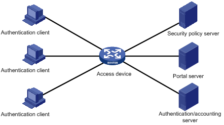
Authentication client
An authentication client is an entity seeking access to network resources. It is typically an end-user terminal, such as a PC. A client can use a browser or portal client software for portal authentication. The security check for a client is implemented through the communications between the client and the security policy server.
Access device
An access device controls user access. It can be a switch or router that provides the following three functions:
· Redirecting all HTTP requests from unauthenticated users to the portal server.
· Interacting with the portal server, the security policy server, and the authentication/accounting server for identity authentication, security check, and accounting.
· Allowing users who have passed identity authentication and security check to access granted Internet resources.
Portal server
A portal server listens to authentication requests from authentication clients and exchanges client authentication information with the access device. It provides free portal services and pushes Web authentication pages to users.
Authentication/accounting server
An authentication/accounting server implements user authentication and accounting through interaction with the access device.
Security policy server
A security policy server interacts with authentication clients and access devices for security check and resource authorization.
The components of a portal system interact in the following procedure:
1. When an unauthenticated user enters a website address in the address bar of the Web browser to access the Internet, an HTTP request is created and sent to the access device, which redirects the HTTP request to the Web authentication homepage of the portal server. For extended portal functions, authentication clients must run the portal client.
2. On the authentication homepage/authentication dialog box, the user enters and submits the authentication information, which the portal server then transfers to the access device.
3. Upon receipt of the authentication information, the access device communicates with the authentication/accounting server for authentication and accounting.
4. After successful authentication, the access device checks whether there is a corresponding security policy for the user. If not, it allows the user to access the Internet. Otherwise, the client communicates with the access device and the security policy server for security check. If the client passes security check, the security policy server authorizes the user to access the Internet resources.
Portal authentication supports NAT traversal, whether it is initiated by a Web client or an H3C iNode. When the portal authentication client is on a private network, but the portal server is on a public network and the access device is enabled with NAT, network address translations performed on the access device do not affect portal authentication. However, in such a case, H3C recommends specifying a public IP address of an interface as the source address of outgoing portal packets.
Only a RADIUS server can serve as the remote authentication/accounting server in a portal system.
To implement security check, the client must be the H3C iNode client.
Portal authentication mode
The switch supports Layer 3 portal authentication.
You can enable Layer 3 authentication on an access device's Layer 3 interfaces that connect authentication clients. Portal authentication performed on a Layer 3 interface can be direct authentication, re-DHCP authentication, or cross-subnet authentication. In direct authentication and re-DHCP authentication mode, no Layer 3 forwarding devices exist between the authentication client and the access device. In cross-subnet authentication mode, Layer 3 forwarding devices may exist between the authentication client and the access device.
Direct authentication
Before authentication, a user manually configures a public IP address or obtains a public IP address through DHCP, and can access only the portal server and predefined free websites. After passing authentication, the user can access network resources. The process of direct authentication is simpler than that of re-DHCP authentication.
Re-DHCP authentication
Before authentication, a user gets a private IP address through DHCP and can access only the portal server and predefined free websites. After passing authentication, the user is allocated a public IP address and can access the network resources. No public IP address is allocated to those who fail authentication. This solves the problem about IP address planning and allocation and proves to be useful. For example, a service provider can allocate public IP addresses to broadband users only when they access networks beyond the residential community network.
IPv6 portal authentication does not support the re-DHCP authentication mode.
Cross-subnet authentication
Before authentication, a user manually configures a public IP address or directly obtains a public IP address through DHCP, and can access only the portal server and predefined free websites. After passing authentication, the user can access the network resources. Cross-subnet authentication allows Layer 3 forwarding devices to be present between the authentication client and the access device.
In re-DHCP authentication and cross-subnet authentication mode, the client's IP address is used for client identification. After a client passes authentication, the access device generates an access control list (ACL) for the client based on the client's IP address to permit packets from the client to go through the access port. Because no Layer 3 devices are present between the authentication clients and the access device in re-DHCP authentication, the access device can directly learn the MAC addresses of the clients, and thus can control user packet forwarding in a more granular way by also using the learnt MAC addresses.
Portal authentication process
Direct authentication process is the same as cross-subnet authentication process. Re-DHCP authentication has a different process because of the presence of two address allocation procedures.
Direct authentication/cross-subnet authentication process (with CHAP/PAP authentication)
Figure 2 Direct authentication/cross-subnet portal authentication process
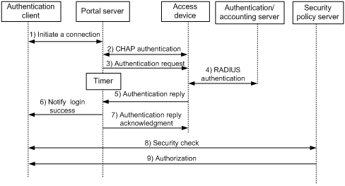
The direct authentication/cross-subnet authentication takes the following procedure:
1. An authentication client initiates authentication by sending an HTTP request. When the HTTP packet arrives at the access device, the access device allows it to pass if it is destined for the portal server or a predefined free website, or redirects it to the portal server if it is destined for other websites. The portal server pushes a Web authentication page to the user and the user enters the username and password.
2. The portal server and the access device exchange Challenge Handshake Authentication Protocol (CHAP) messages. For Password Authentication Protocol (PAP) authentication, this step is skipped.
3. The portal server assembles the username and password into an authentication request message and sends it to the access device. Meanwhile, the portal server starts a timer to wait for an authentication acknowledgment message.
4. The access device and the RADIUS server exchange RADIUS packets to authenticate the user.
5. The access device sends an authentication reply to the portal server.
6. The portal server sends an authentication success message to the authentication client to notify it of logon success.
7. The portal server sends an authentication reply acknowledgment message to the access device.
With extended portal functions, the process includes additional steps:
8. The security policy server exchanges security check information with the authentication client to check whether the authentication client meets the security requirements.
9. Based on the security check result, the security policy server authorizes the user to access certain resources, and sends the authorization information to the access device. The access device then controls access of the user based on the authorization information.
Re-DHCP authentication process (with CHAP/PAP authentication)
Figure 3 Re-DHCP authentication process
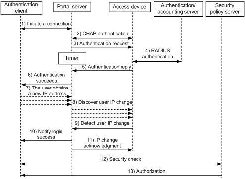
The re-DHCP authentication process takes the following procedure:
Step 1 through step 6 are the same as those in the direct authentication/cross-subnet authentication process.
7. After receiving the authentication success message, the authentication client obtains a new public IP address through DHCP and notifies the portal server that it has obtained a public IP address.
8. The portal server notifies the access device that the authentication client has obtained a new public IP address.
9. Detecting the change of the IP address by examining ARP packets received, the access device notifies the portal server of the change.
10. The portal server notifies the authentication client of logon success.
11. The portal server sends a user IP address change acknowledgment message to the access device.
With extended portal functions, the process includes additional steps:
12. The security policy server exchanges security check information with the authentication client to check whether the authentication client meets the security requirements.
13. Based on the security check result, the security policy server authorizes the user to access certain resources, and sends the authorization information to the access device. The access device then controls access of the user based on the authorization information.
ACL assignment
The device uses ACLs to control user access to network resources and limit user access rights. With authorized ACLs specified on the authentication server, when a user passes authentication, the authentication server assigns an authorized ACL to the user, and the device filters traffic from the user on the access port according to the authorized ACL. You must configure the authorized ACLs on the access device if you specify authorized ACLs on the authentication server. To change the access right of a user, specify a different authorized ACL on the authentication server or change the rules of the corresponding authorized ACL on the device.
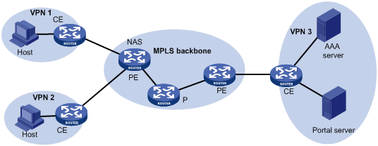
Portal authentication across VPNs
In a scenario where the branches belong to different VPNs that are isolated from each other and all portal users in the branches need to be authenticated by the server at the headquarters, you can deploy portal authentication across MPLS VPNs. As shown in Figure 4, the PE connecting the authentication clients serves as the NAS. The NAS is configured with portal authentication and AAA authentication, both of which support authentication across VPNs. The NAS can transparently transmit a client's portal authentication packets in a VPN through the MPLS backbone to the servers in another VPN. This feature implements centralized authentication of clients present in different VPNs while ensuring the separation of packets of different VPNs.
For information about AAA implementation across VPNs, see "Configuring AAA."
Figure 4 Network diagram for portal authentication across VPNs
|
|
NOTE: · Portal authentication configured on MCE devices can also support authentication across VPNs. For information about MCE, see MPLS Configuration Guide. · This feature is not applicable to VPNs with overlapping address spaces. |
Portal configuration task list
|
Task |
Remarks |
|
|
Required. |
||
|
Required. |
||
|
Optional. |
||
|
Optional. |
||
|
Optional. |
||
|
Specifying an automatic redirection URL for authenticated portal users |
Optional. |
|
|
Optional. |
||
|
Optional. |
||
|
Optional. |
||
|
Optional. |
||
Configuration prerequisites
The portal feature provides a solution for user authentication and security check. However, the portal feature cannot implement this solution by itself. RADIUS authentication needs to be configured on the access device to cooperate with the portal feature to complete user authentication.
The prerequisites for portal authentication are as follows:
· The portal server and the RADIUS server have been installed and configured correctly.
· With re-DHCP authentication, the IP address match check function of DHCP relay agent is enabled on the access device, and the DHCP server is installed and configured correctly.
· The portal client, access device, and servers can reach each other.
· With RADIUS authentication, usernames and passwords of the users are configured on the RADIUS server, and the RADIUS client configurations are performed on the access device. For information about RADIUS client configuration, see "Configuring AAA."
· To implement extended portal functions, you need install and configure the security policy server, CAMS EAD or IMC EAD, and make sure the ACLs configured on the access device correspond to those specified for resources in the quarantined area and restricted resources on the security policy server. For information about security policy server configuration on the access device, see "Configuring AAA."
For installation and configuration about the security policy server, see CAMS EAD Security Policy Help or IMC EAD Security Policy Help.
The ACL for resources in the quarantined area and that for restricted resources correspond to the isolation ACL and the security ACL on the security policy server, respectively.
You can modify the authorized ACL on the access device, but the new ACL takes effect only for portal users who log on after the modification.
Specifying the portal server
Perform this task to specify portal server parameters for Layer 3 portal authentication, including the portal server IP address and port number, the shared encryption key, and the URL address for Web authentication.
To specify an IPv4 portal server for Layer 3 authentication:
|
Step |
Command |
Remarks |
|
1. Enter system view. |
system-view |
N/A |
|
2. Specify an IPv4 portal server and configure related parameters. |
portal server server-name ip ipv4-address [ key [ cipher | simple ] key-string | port port-id | url url-string | vpn-instance vpn-instance-name ] * |
By default, no portal server is specified. To make sure the switch can send packets to the portal server in an MPLS VPN, you must specify the VPN instance to which the portal server belongs when specifying the portal server on the switch. |
To specify an IPv6 portal server for Layer 3 authentication:
|
Step |
Command |
Remarks |
|
1. Enter system view. |
system-view |
N/A |
|
2. Specify an IPv6 portal server and configure related parameters. |
portal server server-name ipv6 ipv6-address [ key [ cipher | simple ] key-string | port port-id | url url-string ] * |
By default, no portal server is specified. |
|
|
NOTE: · The switch (access device) allows you to specify up to eight portal servers. · The configured parameters of a portal server can be modified or deleted only if the portal server is not referenced on any interface. |
Enabling portal authentication
Only after you enable portal authentication on an access interface, can the access interface perform portal authentication for connected clients.
Before enabling Layer 3 portal authentication on an interface, make sure that:
· An IP address is configured for the interface.
· The interface is not added to any port aggregation group.
· The portal server to be referenced on the interface exists.
Configuration restrictions and guidelines
· You cannot enable portal authentication on a Layer 3 interface added to an aggregation group, nor can you add a portal-enabled Layer 3 interface to an aggregation group.
· The destination port number that the switch uses for sending unsolicited packets to the portal server must be the same as that the remote portal server actually uses.
· Cross-subnet authentication mode (portal server server-name method layer3) does not require Layer 3 forwarding devices between the access device and the authentication clients. However, if there are Layer 3 forwarding devices between the authentication client and the access device, you must select the cross-subnet portal authentication mode.
· In re-DHCP authentication mode, a client can use a public IP address to send packets before passing portal authentication. However, responses to the packets are restricted.
· An IPv6 portal server does not support the re-DHCP portal authentication mode.
· You can enable both an IPv4 portal server and an IPv6 portal server for Layer 3 portal authentication on an interface, but you cannot enable two IPv4 or two IPv6 portal servers on the interface.
· The portal server and its parameters can be deleted or modified only when the portal server is not referenced by any interface.
Configuration procedure
To enable Layer 3 portal authentication:
|
Step |
Command |
Remarks |
|
1. Enter system view. |
system-view |
N/A |
|
2. Enter interface view. |
interface interface-type interface-number |
The interface must be a Layer 3 interface. |
|
3. Enable Layer 3 portal authentication on the interface. |
portal server server-name method { direct | layer3 | redhcp } |
Disabled by default. |
Controlling access of portal users
Configuring a portal-free rule
A portal-free rule allows specified users to access specified external websites without portal authentication.
The matching items for a portal-free rule include the source and destination IP address, and VLAN. Packets matching a portal-free rule do not trigger portal authentication, so that users sending the packets can directly access the specified external websites.
Follow these guidelines when you configure a portal-free rule:
· You cannot configure two or more portal-free rules with the same filtering criteria. Otherwise, the system prompts that the rule already exists.
· A Layer 2 interface in an aggregation group cannot be specified as the source interface of a portal-free rule, and the source interface of a portal-free rule cannot be added to an aggregation group.
To configure an IPv4 portal-free rule:
|
Step |
Command |
|
1. Enter system view. |
system-view |
|
2. Configure a portal-free rule. |
portal free-rule rule-number { destination { any | ip { ipv4-address mask { mask-length | mask } | any | hostname } } | source { any | [ interface interface-type interface-number | ip { ipv4-address mask { mask-length | netmask } | any } | mac mac-address | vlan vlan-id ] * } } * |
To configure an IPv6 portal-free rule:
|
Step |
Command |
|
1. Enter system view. |
system-view |
|
2. Configure a portal-free rule. |
portal free-rule rule-number { destination { any | ipv6 { ipv6-address prefix-length | any | hostname } } | source { any | [ interface interface-type interface-number | ipv6 { ipv6-address prefix-length | any } | mac mac-address | vlan vlan-id ] * } } * |
|
|
NOTE: No matter whether portal authentication is enabled, you can only add or remove a portal-free rule. You cannot modify it. |
Configuring an authentication subnet
By configuring authentication subnets, you specify that only HTTP packets from users on the authentication subnets can trigger portal authentication. If an unauthenticated user is not on any authentication subnets, the access device discards all the user's HTTP packets that do not match any portal-free rule.
To configure an IPv4 authentication subnet:
|
Step |
Command |
Remarks |
|
1. Enter system view. |
system-view |
N/A |
|
2. Enter interface view. |
interface interface-type interface-number |
N/A |
|
3. Configure an IPv4 authentication subnet. |
portal auth-network ipv4-network-address { mask-length | mask } |
By default, the IPv4 authentication subnet is 0.0.0.0/0, which means that users from any subnets must pass portal authentication. You can configure multiple IPv4 authentication subnets. |
To configure an IPv6 authentication subnet:
|
Step |
Command |
Remarks |
|
1. Enter system view. |
system-view |
N/A |
|
2. Enter interface view. |
interface interface-type interface-number |
N/A |
|
3. Configure an IPv6 authentication subnet. |
portal auth-network ipv6 ipv6-network-address prefix-length |
By default, the IPv6 authentication subnet is ::/0, which means that users from any subnets must pass portal authentication. You can configure multiple IPv6 authentication subnets. |
|
|
NOTE: Configuration of authentication subnets applies to only cross-subnet authentication. In direct authentication mode, the authentication source subnet is any source IP address. In re-DHCP authentication mode, the authentication subnet of an interface is the subnet to which the private IP address of the interface belongs. |
Setting the maximum number of online portal users
You can use this configuration to control the total number of online portal users in the system.
To set the maximum number of online portal users allowed in the system:
|
Step |
Command |
Remarks |
|
1. Enter system view. |
system-view |
N/A |
|
2. Set the maximum number of online portal users. |
portal max-user max-number |
By default, the maximum number is 32768 when the portal user roaming function is disabled and is 8000 when the portal user roaming function is enabled. |
|
|
NOTE: If the maximum number of online portal users specified in the command is less than that of the current online portal users, the command can be executed successfully and does not impact the online portal users, but the system does not allow new portal users to log on until the number drops down below the limit. |
Specifying an authentication domain for portal users
After you specify an authentication domain for portal users on an interface, the switch uses the authentication domain for authentication, authorization, and accounting (AAA) of all portal users on the interface, ignoring the domain names carried in the usernames. You can specify different authentication domains for different interfaces as needed.
To specify an authentication domain for IPv4 portal users on an interface:
|
Step |
Command |
Remarks |
|
1. Enter system view. |
system-view |
N/A |
|
2. Enter interface view. |
interface interface-type interface-number |
N/A |
|
3. Specify an authentication domain for IPv4 portal users on the interface. |
portal domain domain-name |
By default, no authentication domain is specified for IPv4 portal users. |
To specify an authentication domain for IPv6 portal users on an interface:
|
Step |
Command |
Remarks |
|
1. Enter system view. |
system-view |
N/A |
|
2. Enter interface view. |
interface interface-type interface-number |
N/A |
|
3. Specify an authentication domain for IPv6 portal users on the interface. |
portal domain ipv6 domain-name |
By default, no authentication domain is specified for IPv6 portal users. |
|
|
NOTE: The switch selects the authentication domain for a portal user on an interface in this order: the ISP domain specified for the interface, the ISP domain carried in the username, and the system default ISP domain. For information about the default ISP domain, see "Configuring AAA." |
Specifying NAS-Port-Type for an interface
If there are multiple network devices between the Broadband Access Server (BAS, the portal authentication access device) and a portal client, the BAS may not be able to obtain the correct access port information of a user. For example, for a wireless client using portal authentication, the access port type obtained by the BAS may be the type of the wired port that authenticates the user. To make sure the BAS delivers the correct access port information to the RADIUS server, specify the NAS-Port-Type according to the practical access environment.
To specify the NAS-Port-Type value for an interface:
|
Step |
Command |
Remarks |
|
1. Enter system view. |
system-view |
N/A |
|
2. Enter interface view. |
interface interface-type interface-number |
N/A |
|
3. Specify the NAS-Port-Type value for the interface. |
portal nas-port-type { ethernet | wireless } |
Not configured by default. |
Specifying a source IP address for outgoing portal packets
After you specify a source IP address for outgoing portal packets on an interface, the specified IP address is used as the source IP address of packets that the access device sends to the portal server, and the destination IP address of packets that the portal server sends to the access device.
In NAT environments, H3C recommends specifying the interface's public IP address as the source IP address of outgoing portal packets.
To specify a source IPv4 address for outgoing portal packets:
|
Step |
Command |
Remarks |
|
1. Enter system view. |
system-view |
N/A |
|
2. Enter interface view. |
interface interface-type interface-number |
N/A |
|
3. Specify a source IPv4 address for outgoing portal packets. |
portal nas-ip ipv4-address |
Optional. By default, no source IPv4 address is specified and the IPv4 address of the user logon interface is used as the source IPv4 address of outgoing portal packets. |
To specify a source IPv6 address for outgoing portal packets:
|
Step |
Command |
Remarks |
|
1. Enter system view. |
system-view |
N/A |
|
2. Enter interface view. |
interface interface-type interface-number |
N/A |
|
3. Specify a source IPv6 address for outgoing portal packets. |
portal nas-ip ipv6 ipv6-address |
Optional. By default, no source IPv6 address is specified and the IPv6 address of the user logon interface is used as the source IPv6 address of outgoing portal packets. |
Specifying an automatic redirection URL for authenticated portal users
When an unauthenticated user goes to the portal authentication page for portal authentication, after the user passes portal authentication, if the access device is configured with an automatic redirection URL, it redirects the user to the URL.
To specify an automatic redirection URL for authenticated portal users:
|
Step |
Command |
Remarks |
|
1. Enter system view. |
system-view |
N/A |
|
2. Specify an automatic redirection URL for authenticated portal users. |
portal redirect-url url-string [ wait-time period ] |
By default, an authenticated user is redirected to the URL the user entered in the address bar before portal authentication. The switch does not support the wait-time period option. |
|
|
NOTE: To use this feature for remote Layer 3 portal authentication, the portal server must be an IMC portal server that supports the page autoredirection function. |
Configuring portal detection functions
Configuring the portal server detection function
During portal authentication, if the communication between the access device and portal server is broken off, new portal users are not able to log on and the online portal users are not able to log off correctly. To address this problem, the access device needs to be able to detect the reachability changes of the portal server timely and take corresponding actions to deal with the changes. For example, once detecting that the portal server is unreachable, the access device allows portal users to access network resources without authentication. This function is referred to as portal authentication bypass. It allows for flexible user access control.
With the portal server detection function, the switch (access device) can detect the status of a specific portal server. The specific configurations include:
· Detection methods (you can choose either or both)
¡ Probing HTTP connections—The access device periodically sends TCP connection requests to the HTTP service port of the portal servers configured on its interfaces. If the TCP connection with a portal server can be established, the access device considers that the probe succeeds, that is, the HTTP service of the portal server is open and the portal server is reachable. If the TCP connection cannot be established, the access device considers that the probe fails and the portal server is unreachable.
¡ Probing portal heartbeat packets—A portal server that supports the portal heartbeat function (only the portal server of IMC supports this function) sends portal heartbeat packets to portal access devices periodically. If an access device receives a portal heartbeat packet or an authentication packet within a probe interval, the access device considers that the probe succeeds and the portal server is reachable; otherwise, it considers that the probe fails and the portal server is unreachable.
· Probe parameters
¡ Probe interval—Interval at which probe attempts are made.
¡ Maximum number of probe attempts—Maximum number of consecutive probe attempts allowed. If the number of consecutive probes reaches this value, the access device considers that the portal server is unreachable.
· Actions to be taken when the server reachability status changes (you can choose one or more)
¡ Sending a trap message—When the status of a portal server changes, the access device sends a trap message to the network management server. The trap message contains the name and current state of the portal server.
¡ Sending a log—When the status of a portal server changes, the access device sends a log message. The log message indicates the portal server's name and its current state and original state.
¡ Disabling portal authentication (enabling portal authentication bypass)—When the switch detects that a portal server is unreachable, it disables portal authentication on the interfaces that use the portal server (allows all portal users on the interfaces to access network resources). When the access device receives from the portal server portal heartbeat packets or authentication packets (such as logon requests and logout requests), it re-enables the portal authentication function.
You can configure any combination of the configuration items described above as needed, with respect of the following:
· If both detection methods are specified, a portal server is considered unreachable as long as one detection method fails, and an unreachable portal server is considered recovered only when both detection methods succeed.
· If multiple actions are specified, the switch executes all the specified actions when the status of a portal server changes.
· The detection function configured for a portal server takes effect on an interface only after you enable portal authentication and reference the portal server on the interface.
To configure the portal server detection function:
|
Step |
Command |
Remarks |
|
1. Enter system view. |
system-view |
N/A |
|
2. Configure the portal server detection function. |
portal server server-name server-detect method { http | portal-heartbeat } * action { log | permit-all | trap } * [ interval interval ] [ retry retries ] |
Not configured by default. The portal server specified in the command must exist. |
The portal heartbeat detection method works only when the portal server supports the portal server heartbeat function. Only the IMC portal server supports this function. To implement detection with this method, you also need to configure the portal server heartbeat function on the IMC portal server and make sure the product of interval and retries is greater than or equal to the portal server heartbeat interval. H3C recommends configuring the interval to be greater than the portal server heartbeat interval configured on the portal server.
Configuring portal user information synchronization
Once the switch loses communication with a portal server, the portal user information on the switch and that on the portal server may be inconsistent after the communication resumes. To solve this problem, the switch provides the portal user information synchronization function. This function is implemented by sending and detecting the portal synchronization packet. The process is as follows:
1. The portal server sends the online user information to the switch (access device) in a user synchronization packet at the user heartbeat interval, which is set on the portal server.
2. Upon receiving the user synchronization packet, the switch checks the user information carried in the packet with its own. If the switch finds a nonexistent user in the packet, it informs the portal server of the information and the portal server will delete the user. If the switch finds that one of its users does not appear in the user synchronization packets within N consecutive synchronization probe intervals (N is equal to the value of retries configured in the portal server user-sync command), it considers that the user does not exist on the portal server and logs the user off.
To configure the portal user information synchronization function:
|
Step |
Command |
Remarks |
|
1. Enter system view. |
system-view |
N/A |
|
2. Configure the portal user information synchronization function. |
portal server server-name user-sync [ interval interval ] [ retry retries ] |
Not configured by default. The portal server specified in the command must exist. This function can take effect only when the specified portal server is referenced on the interface connecting the users. |
The user information synchronization function requires that a portal server supports the portal user heartbeat function (only the IMC portal server supports portal user heartbeat). To implement the portal user synchronization function, you also need to configure the user heartbeat function on the portal server and make sure the product of interval and retries is greater than or equal to the portal user heartbeat interval. H3C recommends configuring the interval to be greater than the portal user heartbeat interval configured on the portal server.
For information of the users who are considered nonexistent on the portal server, the switch deletes the information during the (N+1)th interval, where N is equal to the value of retries configured in the portal server user-sync command.
Logging out portal users
Logging out a user terminates the authentication process for the user or removes the user from the authenticated users list.
To log out users:
|
Step |
Command |
|
1. Enter system view. |
system-view |
|
2. Log out users. |
portal delete-user { ipv4-address | all | interface interface-type interface-number | ipv6 ipv6-address } |
Configuring the control mode for portal user packets
The switch can control portal user packets based on MAC addresses or based on both IP and MAC addresses. In MAC control mode, the switch allows a packet to pass if the packet's MAC address is the same as the portal user's MAC address. In IP+MAC control mode, the switch allows a packet to pass if both the MAC and IP addresses of the packet are the same as those of the portal user.
In MAC control mode, the portal authentication mode for IPv4 users and that for IPv6 users must be the same.
In MAC control mode, if only IPv4 portal authentication or IPv6 portal authentication is configured, the device controls traffic on the user access port according to the ACL authorized by the server, regardless of whether the ACL is an IPv4 ACL or an IPv6 ACL. An authorized ACL can be an IPv4 basic ACL, IPv4 advanced ACL, IPv6 basic ACL, or IPv6 advanced ACL.
To configure the control mode for portal user packets:
|
Step |
Command |
|
1. Enter system view. |
system-view |
|
2. Enter interface view. |
interface interface-type interface-number |
|
3. Configure the control mode for portal user packets. |
portal control-mode { ip-mac | mac } |
|
|
NOTE: This function takes effect only to direct and re-DHCP Layer 3 portal authentication. In cross-subnet authentication mode, this function is configurable but does not take effect. |
Enabling portal user roaming
When the portal user roaming function is disabled, if the access port of a portal user changes (for example, from GE3/0/1 to GE3/0/2), the portal user will be re-authenticated even if the original access port and the new access port belong to the same VLAN. After portal user roaming is enabled, a portal-authenticated user does not need re-authentication when the user roams from the current access port to another Layer 2 port of the device as long as the two ports belong to the same VLAN.
When configuring the portal user roaming function, follow these guidelines:
· After configuring this function, you must save the configuration and then restart the device to validate the configuration.
· After this function is enabled, the maximum number of portal users allowed by the device is 8000. If you want to increase this number, you must first disable the portal user roaming function. For more information about setting the maximum number of portal users, see "Setting the maximum number of online portal users."
To enable portal user roaming:
|
Step |
Command |
Remarks |
|
1. Enter system view. |
system-view |
N/A |
|
2. Enable portal user roaming. |
portal-roaming enable |
Optional. By default, portal user roaming is enabled. |
Displaying and maintaining portal
|
Task |
Command |
Remarks |
|
Display the ACLs on a specific interface. |
display portal acl { all | dynamic | static } interface interface-type interface-number [ | { begin | exclude | include } regular-expression ] |
Available in any view. |
|
Display portal connection statistics on a specific interface or all interfaces. |
display portal connection statistics { all | interface interface-type interface-number } [ | { begin | exclude | include } regular-expression ] |
Available in any view. |
|
Display information about a portal-free rule or all portal-free rules. |
display portal free-rule [ rule-number ] [ | { begin | exclude | include } regular-expression ] |
Available in any view. |
|
Display the portal configuration of a specific interface. |
display portal interface interface-type interface-number [ | { begin | exclude | include } regular-expression ] |
Available in any view. |
|
Display information about a specific portal server or all portal servers. |
display portal server [ server-name ] [ | { begin | exclude | include } regular-expression ] |
Available in any view. |
|
Display portal server statistics on a specific interface or all interfaces. |
display portal server statistics { all | interface interface-type interface-number } [ | { begin | exclude | include } regular-expression ] |
Available in any view. |
|
Display TCP spoofing statistics. |
display portal tcp-cheat statistics [ | { begin | exclude | include } regular-expression ] |
Available in any view. |
|
Display information about portal users on a specific interface or all interfaces. |
display portal user { all | interface interface-type interface-number } [ | { begin | exclude | include } regular-expression ] |
Available in any view. |
|
Display the configuration for portal user roaming. |
display portal-roaming [ | { begin | exclude | include } regular-expression ] |
Available in any view. |
|
Clear portal connection statistics on a specific interface or all interfaces. |
reset portal connection statistics {all | interface interface-type interface-number } |
Available in user view. |
|
Clear portal server statistics on a specific interface or all interfaces. |
reset portal server statistics { all | interface interface-type interface-number } |
Available in user view. |
|
Clear TCP spoofing statistics. |
reset portal tcp-cheat statistics |
Available in user view. |
Portal configuration examples
|
|
IMPORTANT: By default, Ethernet interfaces, VLAN interfaces, and aggregate interfaces are in DOWN state. To configure such an interface, first use the undo shutdown command to bring the interface up. |
Configuring direct portal authentication
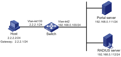
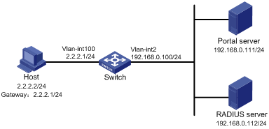
Network requirements
As shown in Figure 5, the host is directly connected to the switch that is configured for direct portal authentication. The host is assigned with a public IP address either manually or through DHCP. Before passing portal authentication, users can access only the portal server. After passing portal authentication, users can access Internet resources.
A RADIUS server serves as the authentication and accounting server.
Configuration prerequisites
· Configure IP addresses for the host, switch, and servers as shown in Figure 5 and make sure they can reach each other.
· Configure the RADIUS server correctly to provide authentication and accounting functions for users.
· If the portal server is an IMC server, the RADIUS server must be an IMC server, too.
Configuring the portal server on IMC PLAT 3.20
This example assumes that the portal server runs on IMC PLAT 3.20-R2602P13 and IMC UAM 3.60-E6301.
1. Configure the portal server:
a. Log in to IMC and select the Service tab.
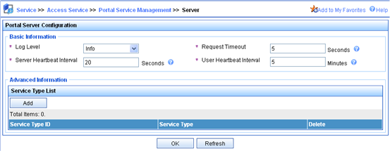
b. Select Portal Service Management > Server from the navigation tree to enter the portal server configuration page, as shown in Figure 6.
c. Configure the portal server parameters as needed.
This example uses the default values.
d. Click OK.
Figure 6 Portal server configuration

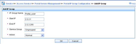
2. Configure the IP address group:
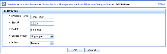
a. Select Portal Service Management > IP Group from the navigation tree to enter the portal IP address group configuration page.
b. Click Add to enter the page shown in Figure 7.
c. Enter the IP group name.
d. Enter the start IP address and end IP address of the IP group.
Make sure the host IP address (2.2.2.2) is in the IP group.
e. Select a service group.
By default, the group Ungrouped is used.
f. Select the IP group type Normal.
g. Click OK.
Figure 7 Adding an IP address group
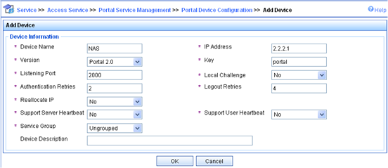
3. Add a portal device:
a. Select Portal Service Management > Device from the navigation tree to enter the portal device configuration page.
b. Click Add to enter the page shown in Figure 8.
c. Enter the device name NAS.
d. Enter the IP address of the switch's interface connected to the user.
e. Enter the key, which must be the same as that configured on the switch.
f. Set whether to enable IP address reallocation.
This example uses direct portal authentication, and therefore select No from the Reallocate IP list.
g. Set whether to support the portal server heartbeat and user heartbeat functions.
In this example, select No for both Support Server Heartbeat and Support User Heartbeat.
h. Click OK.
Figure 8 Adding a portal device
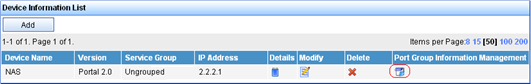
4. Associate the portal device with the IP address group:
a. As shown in Figure 9, click the icon in the Port Group Information Management column of device NAS to enter the port group configuration page.
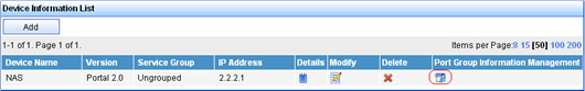
a. Click Add to enter the page shown in Figure 10.
b. Enter the port group name.
c. Select the configured IP address group.
The IP address used by the user to access the network must be within this IP address group.
d. Click OK.
Figure 10 Port group configuration

5. Select Service Parameters > Validate System Configuration from the navigation tree to validate the configurations.
Configuring the portal server on IMC PLAT 5.0
This example assumes that the portal server runs on IMC PLAT 5.0(E0101) and IMC UAM 5.0(E0101).
1. Configure the portal server:
a. Log in to IMC and select the Service tab.
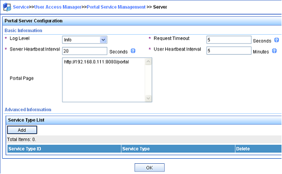
b. Select User Access Manager > Portal Service Management > Server from the navigation tree to enter the portal server configuration page, as shown in Figure 11.
c. Configure the portal server parameters as needed.
This example uses the default settings.
d. Click OK.
Figure 11 Portal server configuration
2. Configure the IP address group:
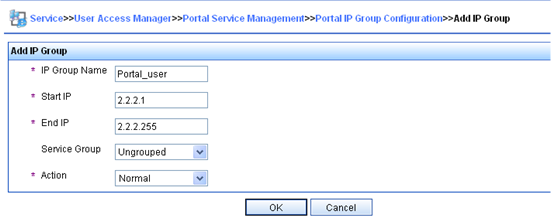
a. Select User Access Manager > Portal Service Management > IP Group from the navigation tree to enter the portal IP address group configuration page.
b. Click Add to enter the page shown in Figure 12.
c. Enter the IP group name.
d. Enter the start IP address and end IP address of the IP group.
Make sure the host IP address is in the IP group.
e. Select a service group.
By default, the group Ungrouped is used.
f. Select the IP group type Normal.
g. Click OK.
Figure 12 Adding an IP address group
3. Add a portal device:
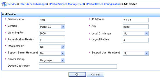
a. Select User Access Manager > Portal Service Management > Device from the navigation tree to enter the portal device configuration page.
b. Click Add to enter the page shown in Figure 13.
c. Enter the device name NAS.
d. Enter the IP address of the switch's interface connected to the user.
e. Enter the key, which must be the same as that configured on the switch.
f. Set whether to enable IP address reallocation.
This example uses direct portal authentication, and therefore select No from the Reallocate IP list.
g. Select whether to support sever heartbeat and user heartbeat functions.
In this example, select No for both Support Server Heartbeat and Support User Heartbeat.
h. Click OK.
Figure 13 Adding a portal device
4. Associate the portal device with the IP address group:
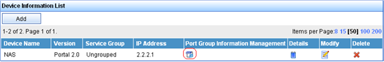
a. As shown in Figure 14, click the icon in the Port Group Information Management column of device NAS to enter the port group configuration page.
b. Click Add to enter the page shown in Figure 15.
c. Enter the port group name.
d. Select the configured IP address group.
The IP address used by the user to access the network must be within this IP address group.
e. Use the default settings for other parameters.
f. Click OK.

5. Select User Access Manager > Service Parameters > Validate System Configuration from the navigation tree to validate the configurations.
Configure the switch
1. Configure a RADIUS scheme:
# Create a RADIUS scheme named rs1 and enter its view.
<Switch> system-view
[Switch] radius scheme rs1
# Set the server type for the RADIUS scheme. When using the CAMS or IMC server, set the server type to extended.
[Switch-radius-rs1] server-type extended
# Specify the primary authentication server and primary accounting server, and configure the keys for communication with the servers.
[Switch-radius-rs1] primary authentication 192.168.0.112
[Switch-radius-rs1] primary accounting 192.168.0.112
[Switch-radius-rs1] key authentication simple radius
[Switch-radius-rs1] key accounting simple radius
# Specify that the ISP domain name should not be included in the username sent to the RADIUS server.
[Switch-radius-rs1] user-name-format without-domain
[Switch-radius-rs1] quit
2. Configure an authentication domain:
# Create an ISP domain named dm1 and enter its view.
[Switch] domain dm1
# Configure AAA methods for the ISP domain.
[Switch-isp-dm1] authentication portal radius-scheme rs1
[Switch-isp-dm1] authorization portal radius-scheme rs1
[Switch-isp-dm1] accounting portal radius-scheme rs1
[Switch-isp-dm1] quit
# Configure domain dm1 as the default ISP domain for all users. Then, if a user enters the username without the ISP domain at logon, the authentication and accounting methods of the default domain are used for the user.
[Switch] domain default enable dm1
3. Configure portal authentication:
# Configure a portal server on the switch, specifying the portal server name as newpt, IP address as 192.168.0.111, key as plaintext string portal, port number as 50100, and URL as http://192.168.0.111:8080/portal.
[Switch] portal server newpt ip 192.168.0.111 key simple portal port 50100 url http://192.168.0.111:8080/portal
# Enable portal authentication on the interface connecting the host.
[Switch] interface vlan-interface 100
[Switch–Vlan-interface100] portal server newpt method direct
[Switch–Vlan-interface100] quit
Configuring re-DHCP portal authentication
Network requirements
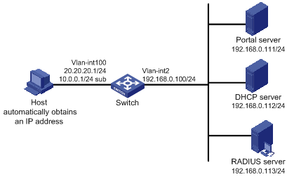
As shown in Figure 16, the host obtains an IP address from the DHCP server.
Configure the switch to perform re-DHCP portal authentication for users on the host. Before a user passes portal authentication, the DHCP server assigns a private IP address to the host. After a user passes portal authentication, the DHCP server assigns a public IP address to the host and then the user can access Internet resources.
Use a RADIUS server serves as the authentication/accounting server.
Configuration prerequisites and guidelines
· Configure IP addresses for the host, switch, and servers as shown in Figure 16 and make sure they can reach each other.
· Configure a public address pool (20.20.20.0/24, in this example) and a private address pool (10.0.0.0/24, in this example) on the DHCP server. (Details not shown.)
· Configure the switch as a DHCP relay agent and configure a primary IP address (a public IP address) and a secondary IP address (a private IP address) for the portal-enabled interface. For DHCP configuration information, see Layer 3—IP Services Configuration Guide.
· Make sure the IP address of the portal device added on the portal server is the public IP address of the interface connecting users (20.20.20.1 in this example), the private IP address range for the IP address group associated with the portal device is the private network segment where the users reside (10.0.0.0/24 in this example), and the public IP address range for the IP address group is the public network segment 20.20.20.0/24.
· Configure the RADIUS server correctly to provide authentication and accounting for users.
Configuration procedure
1. Configure a RADIUS scheme:
# Create a RADIUS scheme named rs1 and enter its view.
<Switch> system-view
[Switch] radius scheme rs1
# Set the server type for the RADIUS scheme. When using the CAMS or IMC server, you need set the server type to extended.
[Switch-radius-rs1] server-type extended
# Specify the primary authentication server and primary accounting server, and configure the keys for communication with the servers.
[Switch-radius-rs1] primary authentication 192.168.0.113
[Switch-radius-rs1] primary accounting 192.168.0.113
[Switch-radius-rs1] key authentication simple radius
[Switch-radius-rs1] key accounting simple radius
# Specify to exclude ISP domain names from the usernames to be sent to the RADIUS server.
[Switch-radius-rs1] user-name-format without-domain
[Switch-radius-rs1] quit
2. Configure an authentication domain:
# Create an ISP domain named dm1 and enter its view.
[Switch] domain dm1
# Configure AAA methods for the ISP domain.
[Switch-isp-dm1] authentication portal radius-scheme rs1
[Switch-isp-dm1] authorization portal radius-scheme rs1
[Switch-isp-dm1] accounting portal radius-scheme rs1
[Switch-isp-dm1] quit
# Configure dm1 as the default ISP domain for all users. Then, if a user enters the username without the ISP domain at logon, the authentication and accounting methods of the default domain are used for the user.
[Switch] domain default enable dm1
3. Configure portal authentication:
# Configure a portal server on the switch, making sure the IP address, key, port number and URL match those of the actual portal server.
[Switch] portal server newpt ip 192.168.0.111 key simple portal port 50100 url http://192.168.0.111:8080/portal
# Configure the switch as a DHCP relay agent, and enable the IP address match check function.
[Switch] dhcp enable
[Switch] dhcp relay server-group 0 ip 192.168.0.112
[Switch] interface vlan-interface 100
[Switch–Vlan-interface100] ip address 20.20.20.1 255.255.255.0
[Switch–Vlan-interface100] ip address 10.0.0.1 255.255.255.0 sub
[Switch-Vlan-interface100] dhcp select relay
[Switch-Vlan-interface100] dhcp relay server-select 0
[Switch-Vlan-interface100] dhcp relay address-check enable
# Enable re-DHCP portal authentication on the interface connecting the host.
[Switch–Vlan-interface100] portal server newpt method redhcp
[Switch–Vlan-interface100] quit
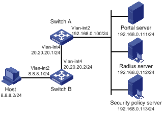
Configuring cross-subnet portal authentication
Network requirements
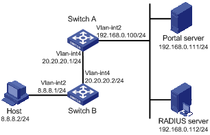
Configure Switch A to perform cross-subnet portal authentication for users on the host. Before passing portal authentication, a user can access only the portal server. After passing portal authentication, the user can access Internet resources.
Use a RADIUS server serves as the authentication/accounting server.
Configuration prerequisites and guidelines
· Make sure the IP address of the portal device added on the portal server is the IP address of the interface connecting users (20.20.20.1 in this example), and the IP address group associated with the portal device is the network segment where the users reside (8.8.8.0/24 in this example).
· Configure IP addresses for the host, switches, and servers as shown in Figure 17 and make sure they can reach each other.
· Configure the RADIUS server correctly to provide authentication and accounting for users.
Configuration procedure
1. Configure a RADIUS scheme:
# Create a RADIUS scheme named rs1 and enter its view.
<SwitchA> system-view
[SwitchA] radius scheme rs1
# Set the server type for the RADIUS scheme. When using the CAMS or IMC server, you need set the server type to extended.
[SwitchA-radius-rs1] server-type extended
# Specify the primary authentication server and primary accounting server, and configure the keys for communication with the servers.
[SwitchA-radius-rs1] primary authentication 192.168.0.112
[SwitchA-radius-rs1] primary accounting 192.168.0.112
[SwitchA-radius-rs1] key authentication simple radius
[SwitchA-radius-rs1] key accounting simple radius
# Specify to exclude ISP domain from the usernames to be sent to the RADIUS server.
[SwitchA-radius-rs1] user-name-format without-domain
[SwitchA-radius-rs1] quit
2. Configure an authentication domain:
# Create an ISP domain named dm1 and enter its view.
[SwitchA] domain dm1
# Configure AAA methods for the ISP domain.
[SwitchA-isp-dm1] authentication portal radius-scheme rs1
[SwitchA-isp-dm1] authorization portal radius-scheme rs1
[SwitchA-isp-dm1] accounting portal radius-scheme rs1
[SwitchA-isp-dm1] quit
# Configure dm1 as the default ISP domain for all users. Then, if a user enters the username without the ISP domain at login, the authentication and accounting methods of the default domain are used for the user.
[SwitchA] domain default enable dm1
3. Configure portal authentication:
# Configure a portal server on the switch, making sure the IP address, key, port number, and URL match those of the actual portal server.
[SwitchA] portal server newpt ip 192.168.0.111 key simple portal port 50100 url http://192.168.0.111:8080/portal
# Enable portal authentication on the interface connecting Switch B.
[SwitchA] interface vlan-interface 4
[SwitchA–Vlan-interface4] portal server newpt method layer3
[SwitchA–Vlan-interface4] quit
On Switch B, you must configure a default route to subnet 192.168.0.0/24, setting the next hop to 20.20.20.1. (Details not shown.)
Configuring direct portal authentication with extended functions
Network requirements
As shown in Figure 18, the host is directly connected to the switch that is configured for direct extended portal authentication. The host is assigned with a public network IP address either manually or through DHCP. If a user fails security check after passing identity authentication, the user can access only subnet 192.168.0.0/24. After the user passes security check, the user can access Internet resources.
A RADIUS server serves as the authentication/accounting server.
Configuration prerequisites
· Configure IP addresses for the host, switch, and servers as shown in Figure 18 and make sure they can reach each other.
· Configure the RADIUS server correctly to provide authentication and accounting functions for users.
Configuration procedure
1. Configure a RADIUS scheme:
# Create a RADIUS scheme named rs1 and enter its view.
<Switch> system-view
[Switch] radius scheme rs1
# Set the server type for the RADIUS scheme. When using the CAMS or IMC server, set the server type to extended.
[Switch-radius-rs1] server-type extended
# Specify the primary authentication server and primary accounting server, and configure the keys for communication with the servers.
[Switch-radius-rs1] primary authentication 192.168.0.112
[Switch-radius-rs1] primary accounting 192.168.0.112
[Switch-radius-rs1] key accounting simple radius
[Switch-radius-rs1] key authentication simple radius
[Switch-radius-rs1] user-name-format without-domain
# Configure the IP address of the security policy server.
[Switch-radius-rs1] security-policy-server 192.168.0.113
[Switch-radius-rs1] quit
2. Configure an authentication domain:
# Create an ISP domain named dm1 and enter its view.
[Switch] domain dm1
# Configure AAA methods for the ISP domain.
[Switch-isp-dm1] authentication portal radius-scheme rs1
[Switch-isp-dm1] authorization portal radius-scheme rs1
[Switch-isp-dm1] accounting portal radius-scheme rs1
[Switch-isp-dm1] quit
# Configure domain dm1 as the default ISP domain for all users. Then, if a user enters the username without the ISP domain at logon, the authentication and accounting methods of the default domain are used for the user.
[Switch] domain default enable dm1
3. Configure the ACL (ACL 3000 ) for resources on subnet 192.168.0.0/24 and the ACL (ACL 3001) for Internet resources:
[Switch] acl number 3000
[Switch-acl-adv-3000] rule permit ip destination 192.168.0.0 0.0.0.255
[Switch-acl-adv-3000] rule deny ip
[Switch-acl-adv-3000] quit
[Switch] acl number 3001
[Switch-acl-adv-3001] rule permit ip
[Switch-acl-adv-3001] quit
Make sure you specify ACL 3000 as the isolation ACL and ACL 3001 as the security ACL on the security policy server.
4. Configure portal authentication:
# Configure the portal server as follows:
¡ Name: newpt
¡ IP address: 192.168.0.111
¡ Key: portal, in plain text
¡ Port number: 50100
¡ URL: http://192.168.0.111:8080/portal
[Switch] portal server newpt ip 192.168.0.111 key simple portal port 50100 url http://192.168.0.111:8080/portal
# Enable portal authentication on the interface connecting the host.
[Switch] interface vlan-interface 100
[Switch–Vlan-interface100] portal server newpt method direct
[Switch–Vlan-interface100] quit
Configuring re-DHCP portal authentication with extended functions
Network requirements
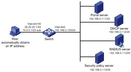
As shown in Figure 19, the host obtains an IP address from the DHCP server. Configure the switch to perform re-DHCP extended portal authentication for users on the host. Use a RADIUS server serves as the authentication/accounting server.
Before a user passes portal authentication, the DHCP server assigns a private IP address to the host. After the user passes portal authentication, the DHCP server assigns a public IP address to the host.
If a user passes identity authentication but fails security check, the user can access only subnet 192.168.0.0/24. After the user passes security check, the user can access Internet resources.
Configuration prerequisites and guidelines
· Configure IP addresses for the host, switch, and servers as shown in Figure 19 and make sure they can reach each other.
· Configure a public address pool (20.20.20.0/24, in this example) and a private address pool (10.0.0.0/24, in this example) on the DHCP server. (Details not shown.)
· Configure the switch as a DHCP relay agent and configure a primary IP address (a public IP address) and a secondary IP address (a private IP address) for the portal-enabled interface. For DHCP relay configuration information, see Layer 3—IP Services Configuration Guide.
· Make sure the IP address of the portal device added on the portal server is the public IP address of the interface connecting users (20.20.20.1 in this example), the private IP address range for the IP address group associated with the portal device is the private network segment where the users reside (10.0.0.0/24 in this example), and the public IP address range for the IP address group is the public network segment 20.20.20.0/24.
· Configure the RADIUS server correctly to provide authentication and accounting for users.
Configuration procedure
1. Configure a RADIUS scheme:
# Create a RADIUS scheme named rs1 and enter its view.
<Switch> system-view
[Switch] radius scheme rs1
# Set the server type for the RADIUS scheme. When using the CAMS or IMC server, you need set the server type to extended.
[Switch-radius-rs1] server-type extended
# Specify the primary authentication server and primary accounting server, and configure the keys for communication with the servers.
[Switch-radius-rs1] primary authentication 192.168.0.113
[Switch-radius-rs1] primary accounting 192.168.0.113
[Switch-radius-rs1] key accounting simple radius
[Switch-radius-rs1] key authentication simple radius
# Specify to exclude ISP domains from the usernames to be sent to the RADIUS server.
[Switch-radius-rs1] user-name-format without-domain
# Configure the IP address of the security policy server.
[Switch-radius-rs1] security-policy-server 192.168.0.114
[Switch-radius-rs1] quit
2. Configure an authentication domain:
# Create an ISP domain named dm1 and enter its view.
[Switch] domain dm1
# Configure AAA methods for the ISP domain.
[Switch-isp-dm1] authentication portal radius-scheme rs1
[Switch-isp-dm1] authorization portal radius-scheme rs1
[Switch-isp-dm1] accounting portal radius-scheme rs1
[Switch-isp-dm1] quit
# Configure dm1 as the default ISP domain for all users. Then, if a user enters the username without the ISP domain at logon, the authentication and accounting methods of the default domain are used for the user.
[Switch] domain default enable dm1
3. Configure the ACL (ACL 3000 ) for resources on subnet 192.168.0.0/24 and the ACL (ACL 3001) for Internet resources.
On the security policy server, specify ACL 3000 as the isolation ACL and ACL 3001 as the security ACL.
[Switch] acl number 3000
[Switch-acl-adv-3000] rule permit ip destination 192.168.0.0 0.0.0.255
[Switch-acl-adv-3000] rule deny ip
[Switch-acl-adv-3000] quit
[Switch] acl number 3001
[Switch-acl-adv-3001] rule permit ip
[Switch-acl-adv-3001] quit
4. Configure portal authentication:
# Configure a portal server on the switch, making sure the IP address, key, port number and URL match those of the actual portal server.
[Switch] portal server newpt ip 192.168.0.111 key simple portal port 50100
url http://192.168.0.111:8080/portal
# Configure the switch as a DHCP relay agent, and enable the IP address match check function.
[Switch] dhcp enable
[Switch] dhcp relay server-group 0 ip 192.168.0.112
[Switch] interface vlan-interface 100
[Switch–Vlan-interface100] ip address 20.20.20.1 255.255.255.0
[Switch–Vlan-interface100] ip address 10.0.0.1 255.255.255.0 sub
[Switch-Vlan-interface100] dhcp select relay
[Switch-Vlan-interface100] dhcp relay server-select 0
[Switch-Vlan-interface100] dhcp relay address-check enable
# Enable re-DHCP portal authentication on the interface connecting the host.
[Switch–Vlan-interface100] portal server newpt method redhcp
[Switch–Vlan-interface100] quit
Configuring cross-subnet portal authentication with extended functions
Network requirements
Configure Switch A to perform cross-subnet extended portal authentication for users on the host. If a user passes identity authentication but fails security check, the user can access only subnet 192.168.0.0/24. After the user passes security check, the user can access Internet resources.
Use a RADIUS server serves as the authentication/accounting server.
Configuration prerequisites and guidelines
· Make sure the IP address of the portal device added on the portal server is the IP address of the interface connecting users (20.20.20.1 in this example), and the IP address group associated with the portal device is the network segment where the users reside (8.8.8.0/24 in this example).
· Configure IP addresses for the host, switches, and servers as shown in Figure 20 and make sure they can reach each other.
· Configure the RADIUS server correctly to provide authentication and accounting for users.
Configuration procedure
1. Configure a RADIUS scheme:
# Create a RADIUS scheme named rs1 and enter its view.
<SwitchA> system-view
[SwitchA] radius scheme rs1
# Set the server type for the RADIUS scheme. When using the CAMS or IMC server, you need set the server type to extended.
[SwitchA-radius-rs1] server-type extended
# Specify the primary authentication server and primary accounting server, and configure the keys for communication with the servers.
[SwitchA-radius-rs1] primary authentication 192.168.0.112
[SwitchA-radius-rs1] primary accounting 192.168.0.112
[SwitchA-radius-rs1] key accounting simple radius
[SwitchA-radius-rs1] key authentication simple radius
# Specify to exclude ISP domain from the usernames to be sent to the RADIUS server.
[SwitchA-radius-rs1] user-name-format without-domain
# Configure the IP address of the security policy server.
[SwitchA-radius-rs1] security-policy-server 192.168.0.113
[SwitchA-radius-rs1] quit
2. Configure an authentication domain:
# Create an ISP domain named dm1 and enter its view.
[SwitchA] domain dm1
# Configure AAA methods for the ISP domain.
[SwitchA-isp-dm1] authentication portal radius-scheme rs1
[SwitchA-isp-dm1] authorization portal radius-scheme rs1
[SwitchA-isp-dm1] accounting portal radius-scheme rs1
[SwitchA-isp-dm1] quit
# Configure dm1 as the default ISP domain for all users. Then, if a user enters the username without the ISP domain at login, the authentication and accounting methods of the default domain are used for the user.
[SwitchA] domain default enable dm1
3. Configure the ACL (ACL 3000 ) for resources on segment 192.168.0.0/24 and the ACL (ACL 3001) for Internet resources.
|
|
NOTE: On the security policy server, specify ACL 3000 as the isolation ACL and ACL 3001 as the security ACL. |
[SwitchA] acl number 3000
[SwitchA-acl-adv-3000] rule permit ip destination 192.168.0.0 0.0.0.255
[SwitchA-acl-adv-3000] rule deny ip
[SwitchA-acl-adv-3000] quit
[SwitchA] acl number 3001
[SwitchA-acl-adv-3001] rule permit ip
[SwitchA-acl-adv-3001] quit
4. Configure portal authentication:
# Configure a portal server on the switch, making sure the IP address, key, port number, and URL match those of the actual portal server.
[SwitchA] portal server newpt ip 192.168.0.111 key simple portal port 50100 url http://192.168.0.111:8080/portal
# Enable portal authentication on the interface connecting Switch B.
[SwitchA] interface vlan-interface 4
[SwitchA–Vlan-interface4] portal server newpt method layer3
[SwitchA–Vlan-interface4] quit
On Switch B, you must configure a default route to subnet 192.168.0.0/24, setting the next hop to 20.20.20.1. (Details not shown.)
Configuring portal server detection and portal user information synchronization
Network requirements
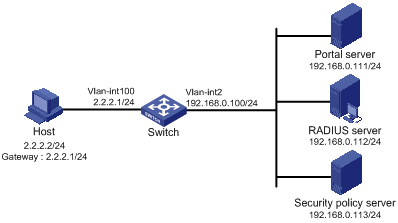
As shown in Figure 21, a host is connected to the switch and must pass portal authentication to access the Internet. A RADIUS server serves as the authentication/accounting server.
The host is assigned a public network IP address either manually or through DHCP. Before passing portal authentication, the host can access only the portal server. After passing portal authentication, the host can access the Internet.
The switch can detect whether the portal server is reachable and send trap messages upon the portal server's reachability state changes. When the portal server is unreachable due to, for example, a connection failure, network device failure, or portal server failure, the switch can disable portal authentication, allowing users to access the Internet without authentication.
The switch can synchronize portal user information with the portal server periodically.
Configuration considerations
1. Configure the portal server and enable portal server heartbeat function and the portal user heartbeat function.
2. Configure the RADIUS server to implement authentication and accounting.
3. Configure cross-subnet portal authentication on interface VLAN-interface 4 of the switch.
4. Configure the portal server detection function on the switch, so that the switch can detect the status of the portal server by cooperating with the portal server heartbeat function.
5. Configure the portal user information synchronization function, so that the switch can synchronize portal user information with the portal server by cooperating with the portal user heartbeat function.
Configuration prerequisites
· Configure IP addresses for the host, switch, and servers as shown in Figure 21 and make sure they can reach each other.
· Configure the RADIUS server correctly to provide authentication and accounting for users.
· If the portal server is an IMC server, the RADIUS server must be an IMC server, too.
Configuring the portal server (IMC PLAT 3.20).
This example assumes that the portal server runs on IMC PLAT 3.20-R2606P13 and IMC UAM 3.60-E6301.
1. Configure the portal server:
a. Log in to IMC and select the Service tab.
b. Select Portal Service Management > Server from the navigation tree to enter the portal server configuration page, as shown in Figure 22.
c. Configure the portal server heartbeat interval and user heartbeat interval.
d. Use default values for other parameters.
e. Click OK.
Figure 22 Portal server configuration
2. Configure the IP address group:
a. Select Portal Service Management > IP Group from the navigation tree to enter the portal IP address group configuration page.
b. Click Add to enter the page as shown in Figure 23.
c. Enter the IP group name.
d. Enter the start IP address and end IP address of the IP group. Make sure the IP address of the user host is in the IP group.
e. Select a service group. By default, the group Ungrouped is used.
f. Select the IP group type Normal.
g. Click OK.
Figure 23 Adding an IP address group
3. Add a portal device:
a. Select Portal Service Management > Device from the navigation tree to enter the portal device configuration page.
b. Click Add to enter the page as shown in Figure 24.
c. Enter the device name NAS.
d. Enter the IP address of the switch's interface connected to the user.
e. Enter the key, which must be the same as that configured on the switch.
f. Specify whether to enable IP address reallocation. Cross-subnet portal authentication is used in this example, and therefore select No from the Reallocate IP list.
g. Select Yes for both Support Server Heartbeat and Support User Heartbeat.
h. Click OK.
Figure 24 Adding a portal device

4. Associate the portal device with the IP address group:
a. As shown in Figure 25, on the device list, click the icon in the Port Group Information Management column of device NAS to enter the port group configuration page.
b. Click Add to enter the page as shown in Figure 26. Perform the following configurations:
c. Enter the port group name.
d. Select the configured IP address group. Note that the IP address used by the user to access the network must be within this IP address group.
e. Use the default settings for other parameters.
5. Select Service Parameters > Validate System Configuration from the navigation tree to validate the configurations.
Configuring the portal server (IMC PLAT 5.0)
This example assumes that the portal server runs on IMC PLAT 5.0(E0101) and IMC UAM 5.0(E0101).
1. Configure the portal server:
a. Log in to IMC and select the Service tab.
b. Select Portal Service Management > Server from the navigation tree to enter the portal server configuration page, as shown in Figure 27.
c. Configure the portal server heartbeat interval and user heartbeat interval.
d. Use default values for other parameters.
e. Click OK.
Figure 27 Portal server configuration
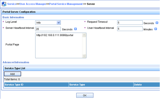
2. Configure the IP address group:
a. Select Portal Service Management > IP Group from the navigation tree to enter the portal IP address group configuration page.
b. Click Add to enter the page shown in Figure 28.
c. Enter the IP group name.
d. Enter the start IP address and end IP address of the IP group. Make sure the IP address of the user host is in the IP group.
e. Select a service group. By default, the group Ungrouped is used.
f. Select the IP group type Normal.
g. Click OK.
Figure 28 Adding an IP address group

3. Add a portal device:
a. Select User Access Manager > Portal Service Management > Device from the navigation tree to enter the portal device configuration page.
b. Click Add to enter the page shown in Figure 29.
c. Enter the device name NAS.
d. Enter the IP address of the switch's interface connected to the user.
e. Enter the key, which must be the same as that configured on the switch.
f. Set whether to enable IP address reallocation. This example uses direct portal authentication, and therefore select No from the Reallocate IP list.
g. Select Yes for both Support Server Heartbeat and Support User Heartbeat.
h. Click OK.
Figure 29 Adding a portal device
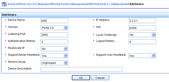
4. Associate the portal device with the IP address group:
a. As shown in Figure 30, click the icon in the Port Group Information Management column of device NAS to enter the port group configuration page.
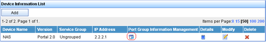
b. On the port group configuration page, click Add to enter the page shown in Figure 31. Perform the following configurations:
c. Enter the port group name.
d. Select the configured IP address group. The IP address used by the user to access the network must be within this IP address group.
e. Use the default settings for other parameters.
f. Click OK.
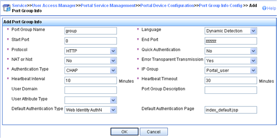
5. Select Service Parameters > Validate System Configuration from the navigation tree to validate the configurations.
Configuring the switch
1. Configure a RADIUS scheme:
# Create RADIUS scheme rs1 and enter its view.
<Switch> system-view
[Switch] radius scheme rs1
# Configure the server type for the RADIUS scheme. When using the IMC server, you must configure the RADIUS server type as extended.
[Switch-radius-rs1] server-type extended
# Specify the primary authentication server and primary accounting server, and configure the keys for communication with the servers.
[Switch-radius-rs1] primary authentication 192.168.0.112
[Switch-radius-rs1] primary accounting 192.168.0.112
[Switch-radius-rs1] key authentication simple radius
[Switch-radius-rs1] key accounting simple radius
# Configure the access device to not carry the ISP domain name in the username sent to the RADIUS server.
[Switch-radius-rs1] user-name-format without-domain
[Switch-radius-rs1] quit
2. Configure an authentication domain:
# Create ISP domain dm1 and enter its view.
[Switch] domain dm1
# Configure AAA methods for the ISP domain.
[Switch-isp-dm1] authentication portal radius-scheme rs1
[Switch-isp-dm1] authorization portal radius-scheme rs1
[Switch-isp-dm1] accounting portal radius-scheme rs1
[Switch-isp-dm1] quit
# Configure dm1 as the default ISP domain for all users. Then, if a user enters a username without the ISP domain at logon, the authentication and accounting methods of the default domain are used for the user.
[Switch] domain default enable dm1
3. Configure portal authentication:
# Configure the portal server on the switch, making sure the IP address, key, port number, and URL match those of the actual portal server.
[Switch] portal server newpt ip 192.168.0.111 key simple portal port 50100 url http://192.168.0.111:8080/portal
# Enable portal authentication on the interface connecting the host.
[Switch] interface vlan-interface 100
[Switch–Vlan-interface100] portal server newpt method layer3
[Switch–Vlan-interface100] quit
4. Configure the portal server detection function:
# Configure the access device to detect portal server newpt, specifying the detection method as portal heartbeat probe, setting the server probe interval to 40 seconds, and specifying the access device to send a server unreachable trap message and disable portal authentication to permit unauthenticated portal users if two consecutive probes fail.
[Switch] portal server newpt server-detect method portal-heartbeat action trap permit-all interval 40 retry 2
|
|
NOTE: The product of interval and retry must be greater than or equal to the portal server heartbeat interval, and H3C recommends configuring the interval as a value greater than the portal server heartbeat interval configured on the portal server. |
5. Configure portal user synchronization
# Configure the access device to synchronize portal user information with portal server newpt, setting the synchronization probe interval to 600 seconds, and specifying the access device to log off users if the users do not appear in the user synchronization packets sent from the server in two consecutive probe intervals.
[Switch] portal server newpt user-sync interval 600 retry 2
|
|
NOTE: The product of interval and retry must be greater than or equal to the portal user heartbeat interval, and H3C recommends configuring the interval as a value greater than the portal user heartbeat interval configured on the portal server. |
Verifying the configuration
Use the following command to view information about the portal server.
<Switch> display portal server newpt
Portal server:
1)newpt:
IP : 192.168.0.111
Key : ******
Port : 50100
URL : http://192.168.0.111:8080/portal
Status : Up
The Up state of the portal server indicates that the portal server is reachable. If the access device detects that the portal server is unreachable, you can see the portal server status is Down in the output, and the access device generates a server unreachable trap "portal server newpt lost" and disables portal authentication on the access interface, so the client can access the external network without authentication.
Cross-subnet portal authentication across VPNs
Network requirements
As shown in Figure 32, Switch A, as the PE connecting the user side, needs to provide Layer 3 portal authentication for hosts in VPN 1. The RADIUS server/portal server is in VPN 3.
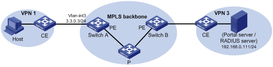
Configuration prerequisites and guidelines
· Before enabling portal authentication, be sure to configure the MPLS L3VPN capabilities correctly and specify VPN targets for VPN 1 and VPN 3 so that VPN 1 and VPN 3 can communicate with each other. This example gives only the access authentication configuration on the user-side PE. For information about MPLS L3VPN, see MPLS Configuration Guide.
· Configure the RADIUS server correctly to provide normal authentication/accounting functions for users.
Configuration procedure
1. Configure a RADIUS scheme:
# Create a RADIUS scheme named rs1 and enter its view.
<SwitchA> system-view
[SwitchA] radius scheme rs1
# Configure the VPN instance to which the RADIUS scheme belongs as vpn3.
[SwitchA-radius-rs1] vpn-instance vpn3
# Set the server type for the RADIUS scheme. When using the CAMS or IMC server, you must set the server type to extended.
[SwitchA-radius-rs1] server-type extended
# Specify the primary authentication server and primary accounting server, and configure the keys for communication with the servers.
[SwitchA-radius-rs1] primary authentication 192.168.0.111
[SwitchA-radius-rs1] primary accounting 192.168.0.111
[SwitchA-radius-rs1] key accounting simple radius
[SwitchA-radius-rs1] key authentication simple radius
# Configure the switch to not carry the ISP domain name in the username sent to the RADIUS server.
[SwitchA-radius-rs1] user-name-format without-domain
# Specify the source IP address for RADIUS packets to be sent as 3.3.0.3.
[SwitchA-radius-rs1] nas-ip 3.3.0.3
[SwitchA-radius-rs1] quit
|
|
IMPORTANT: Use the nas-ip command to specify the source IP address for RADIUS packets to be sent, and make sure the source IP address is consistent with the IP address of the access device specified on the server to avoid authentication failures. |
2. Configure an authentication domain:
# Create an ISP domain named dm1 and enter its view.
[SwitchA] domain dm1
# Configure AAA methods for the ISP domain.
[SwitchA-isp-dm1] authentication portal radius-scheme rs1
[SwitchA-isp-dm1] authorization portal radius-scheme rs1
[SwitchA-isp-dm1] accounting portal radius-scheme rs1
[SwitchA-isp-dm1] quit
# Configure dm1 as the default ISP domain for all users. Then, if a user enters a username without any ISP domain at logon, the authentication and accounting methods of the default domain are used for the user.
[SwitchA] domain default enable dm1
3. Configure portal authentication:
# Configure the portal server as follows:
¡ Name: newpt
¡ IP address: 192.168.0.111
¡ VPN: vpn3
¡ Key: portal, in plain text
¡ Port number: 50100
¡ URL: http://192.168.0.111:8080/portal.
[SwitchA] portal server newpt ip 192.168.0.111 vpn-instance vpn3 key simple portal port 50100 url http://192.168.0.111:8080/portal
# Enable Layer 3 portal authentication on the interface connecting the user side.
[SwitchA] interface vlan-interface 3
[SwitchA–Vlan-interface3] portal server newpt method layer3
[SwitchA–Vlan-interface3] quit
Verifying the configuration
Execute the display portal interface command to check whether the portal configuration has taken effect. After Host passes portal authentication, perform the display portal user command to view information about online portal users on Switch A.
[SwitchA] display portal user all
Index:2
State:ONLINE
SubState:NONE
ACL:NONE
Work-mode:stand-alone
VPN instance:vpn1
MAC IP Vlan Interface
----------------------------------------------------------------------------
000d-88f7-c268 3.3.0.1 3 Vlan-interface3
Total 1 user(s) matched, 1 listed.
Troubleshooting portal
Inconsistent keys on the access device and the portal server
Symptom
When a user is forced to access the portal server, the portal server displays neither the portal authentication page nor any error message. What the user sees is a blank webpage.
Analysis
The keys configured on the access device and those on the portal server are inconsistent, causing CHAP message exchange failure. As a result, the portal server does not display the authentication page.
Solution
· Use the display portal server command to display the key for the portal server on the access device and view the key for the access device on the portal server.
· Use the portal server command to modify the key on the access device or modify the key for the access device on the portal server to make sure the keys are consistent.
Incorrect server port number on the access device
Symptom
After a user passes the portal authentication, you cannot force the user to log out by executing the portal delete-user command on the access device, but the user can log out by using the disconnect attribute on the authentication client.
Analysis
When you execute the portal delete-user command on the access device to force the user to log out, the access device actively sends a REQ_LOGOUT message to the portal server. The default listening port of the portal server is 50100. However, if the listening port configured on the access device is not 50100, the destination port of the REQ_LOGOUT message is not the actual listening port on the server. Thus, the portal server cannot receive the REQ_LOGOUT message. As a result, you cannot force the user to log out the portal server.
When the user uses the disconnect attribute on the client to log out, the portal server actively sends a REQ_LOGOUT message to the access device. The source port is 50100 and the destination port of the ACK_LOGOUT message from the access device is the source port of the REQ_LOGOUT message so that the portal server can receive the ACK_LOGOUT message correctly, no matter whether the listening port is configured on the access device. Therefore, the user can log out the portal server.
Solution
Use the display portal server command to display the listening port of the portal server on the access device and use the portal server command in the system view to modify it to make sure it is the actual listening port of the portal server.