- Table of Contents
- Related Documents
-
| Title | Size | Download |
|---|---|---|
| 06-IP Source Guard Configuration | 89.53 KB |
Table of Contents
1 IP Source Guard Configuration
Configuring a Static Binding Entry
Configuring Dynamic Binding Function
Displaying and Maintaining IP Source Guard
IP Source Guard Configuration Examples
Static Binding Entry Configuration Example
Dynamic Binding Function Configuration Example I
Dynamic Binding Function Configuration Example II
Troubleshooting IP Source Guard
Failed to Configure Static Binding Entries and Dynamic Binding Function
When configuring IP Source Guard, go to these sections for information you are interested in:
l Configuring a Static Binding Entry
l Configuring Dynamic Binding Function
l Displaying and Maintaining IP Source Guard
l IP Source Guard Configuration Examples
l Troubleshooting IP Source Guard
IP Source Guard Overview
By filtering packets on a per-port basis, IP source guard prevents illegal packets from traveling through, thus improving the network security. After receiving a packet, the port looks up the key attributes (including IP address, MAC address and VLAN tag) of the packet in the binding entries of the IP source guard. If there is a match, the port forwards the packet. Otherwise, the port discards the packet.
IP source guard filters packets based on the following types of binding entries:
l IP-port binding entry
l MAC-port binding entry
l IP-MAC-port binding entry
You can manually set static binding entries, or use DHCP snooping to provide dynamic binding entries. Binding is on a per-port basis. After a binding entry is configured on a port, it is effective only to the port.
![]()
Enabling IP source guard on a port is mutually exclusive with adding the port to an aggregation group and adding the port to a service loopback group.
Configuring a Static Binding Entry
Follow these steps to configure a static binding entry:
|
To do… |
Use the command… |
Remarks |
|
Enter system view |
system-view |
— |
|
Enter interface view |
interface interface-type interface-number |
— |
|
Configure a static binding entry |
user-bind { ip-address ip-address | ip-address ip-address mac-address mac-address | mac-address mac-address } |
Required No static binding entry exists by default. |
![]()
l The system does not support repeatedly configuring a binding entry to one port. A binding entry can be configured to multiple ports.
l In a valid binding entry, the MAC address cannot be all 0s, all Fs (a broadcast address), or a multicast address, and the IP address can only be a Class A, Class B, or Class C address and can be neither 127.x.x.x nor 0.0.0.0.
l A static binding entry can be configured on only Layer-2 Ethernet ports.
Configuring Dynamic Binding Function
After the dynamic binding function is enabled on a port, IP source guard will receive and process corresponding DHCP snooping entries, which contain such information as MAC address, IP address, VLAN tag, port information or entry type. It adds the obtained information to the dynamic binding entries to enable the port to filter packets according to the binding entries.
Follow these steps to configure port filtering:
|
To do… |
Use the command… |
Remarks |
|
Enter system view |
system-view |
— |
|
Enter interface view |
interface interface-type interface-number |
— |
|
Configure dynamic binding function |
ip check source { ip-address | ip-address mac-address | mac-address } |
Required Not configured by default |
l The dynamic binding function can be configured on Layer 2 Ethernet port and VLAN interfaces.
l A port takes only the latest dynamic binding entries configured on it.
Displaying and Maintaining IP Source Guard
|
To do… |
Use the command… |
Remarks |
|
Display information about static binding entries |
display user-bind [ interface interface-type interface-number | ip-address ip-address | mac-address mac-address ] |
Available in any view |
|
Display information about dynamic binding entries |
display ip check source [ interface interface-type interface-number | ip-address ip-address | mac-address mac-address ] |
Available in any view |
IP Source Guard Configuration Examples
Static Binding Entry Configuration Example
Network requirements
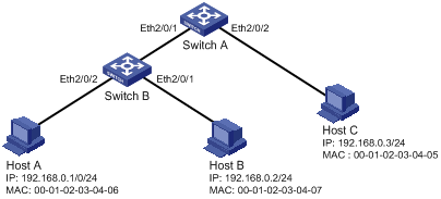
As shown in Figure 1-1, Host A and Host B are connected to ports Ethernet 2/0/2 and Ethernet 2/0/1 of Switch B respectively, Host C is connected to port Ethernet 2/0/2 of Switch A, and Switch B is connected to port Ethernet 2/0/1 of Switch A.
Configure static binding entries on Switch A and Switch B to meet the following requirements:
l On port Ethernet 2/0/2 of Switch A, only IP packets from Host C can pass.
l On port Ethernet 2/0/1 of Switch A, only IP packets from Host A can pass.
l On port Ethernet 2/0/2 of Switch B, only IP packets from Host A can pass.
l On port Ethernet 2/0/1 of Switch B, only IP packets from Host B can pass.
Network diagram
Figure 1-1 Network diagram for configuring static binding entries
Configuration procedure
1) Configure Switch A
# Configure the IP addresses of various interfaces (omitted).
# Configure port Ethernet 2/0/2 of Switch A to allow only IP packets with the source MAC address of 00-01-02-03-04-05 and the source IP address of 192.168.0.3 to pass.
<SwitchA> system-view
[SwitchA] interface ethernet 2/0/2
[SwitchA-Ethernet2/0/2] user-bind ip-address 192.168.0.3 mac-address 0001-0203-0405
[SwitchA-Ethernet2/0/2] quit
# Configure port Ethernet 2/0/1 of Switch A to allow only IP packets with the source MAC address of 00-01-02-03-04-06 and the source IP address of 192.168.0.1 to pass.
[SwitchA] interface ethernet 2/0/1
[SwitchA-Ethernet2/0/1] user-bind ip-address 192.168.0.1 mac-address 0001-0203-0406
2) Configure Switch B
# Configure the IP addresses of various interfaces (omitted).
# Configure port Ethernet 2/0/2 of Switch B to allow only IP packets with the source MAC address of 00-01-02-03-04-06 and the source IP address of 192.168.0.1 to pass.
<SwitchB> system-view
[SwitchB] interface ethernet 2/0/2
[SwitchB-Ethernet2/0/2] user-bind ip-address 192.168.0.1 mac-address 0001-0203-0406
[SwitchB-Ethernet2/0/2] quit
# Configure port Ethernet 2/0/1 of Switch B to allow only IP packets with the source MAC address of 00-01-02-03-04-07 and the source IP address of 192.168.0.2 to pass.
[SwitchB] interface ethernet 2/0/1
[SwitchB-Ethernet2/0/1] user-bind ip-address 192.168.0.2 mac-address 0001-0203-0407
3) Verify the configuration
# On Switch A, static binding entries are configured successfully.
<SwitchA> display user-bind
Total entries found: 2
MAC IP Vlan Port Status
0001-0203-0405 192.168.0.3 N/A Ethernet2/0/2 Static
0001-0203-0406 192.168.0.1 N/A Ethernet2/0/1 Static
# On Switch B, static binding entries are configured successfully.
<SwitchB> display user-bind
Total entries found: 2
MAC IP Vlan Port Status
0001-0203-0406 192.168.0.1 N/A Ethernet2/0/2 Static
0001-0203-0407 192.168.0.2 N/A Ethernet2/0/1 Static
Dynamic Binding Function Configuration Example I
Network requirements
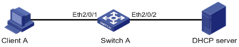
Switch A connects to Client A and the DHCP server through ports Ethernet 2/0/1 and Ethernet 2/0/2 respectively. DHCP snooping is enabled on Switch A.
Detailed requirements are as follows:
l Client A (with the MAC address of 00-01-02-03-04-06) obtains an IP address through the DHCP server.
l On Switch A, create a DHCP snooping entry for Client A.
l On port Ethernet 2/0/1 of Switch A, enable dynamic binding function to prevent attackers from using forged IP addresses to attack the server.
![]()
For detailed configuration of a DHCP server, refer to DHCP Configuration in the IP Service Volume.
Network diagram
Figure 1-2 Network diagram for configuring dynamic binding function I
Configuration procedure
1) Configure Switch A
# Configure dynamic binding function on port Ethernet 2/0/1.
<SwitchA> system-view
[SwitchA] interface ethernet2/0/1
[SwitchA-Ethernet2/0/1] ip check source ip-address mac-address
[SwitchA-Ethernet2/0/1] quit
# Enable DHCP snooping.
[SwitchA] dhcp-snooping
# Configure the port connecting to the DHCP server as a trusted port.
[SwitchA] interface ethernet 2/0/2
[SwitchA-Ethernet2/0/2] dhcp-snooping trust
[SwitchA-Ethernet2/0/2] quit
2) Verify the configuration
# Display dynamic binding function is configured successfully on port Ethernet 2/0/1.
[SwitchA] interface ethernet 2/0/1
[SwitchA-Ethernet2/0/1] display this
#
interface Ethernet2/0/1
ip check source ip-address mac-address
#
return
# Display the dynamic binding entries that port Ethernet 2/0/1 has obtained from DHCP snooping.
[SwitchA-Ethernet2/0/1] display ip check source
Total entries found: 1
MAC IP Vlan Port Status
0001-0203-0406 192.168.0.1 1 Ethernet 2/0/1 DHCP-SNP
# Display the dynamic entries of DHCP snooping and check it is identical with the dynamic entries that port Ethernet 2/0/1 has obtained.
[SwitchA-Ethernet2/0/1] display dhcp-snooping
DHCP Snooping is enabled.
The client binding table for all untrusted ports.
Type : D--Dynamic , S--Static
Type IP Address MAC Address Lease VLAN Interface
==== =============== ============== ============ ==== =================
D 192.168.0.1 0001-0203-0406 86335 1 Ethernet2/0/1
As you see, port Ethernet 2/0/1 has obtained the dynamic entries generated by DHCP snooping after it is configured with dynamic binding function.
Dynamic Binding Function Configuration Example II
Network requirements
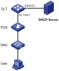
l The S7500E switch acting as an OLT device is connected to the DHCP server through GigabitEthernet 2/0/1 and connected to an ONU through OLT 3/0/1. UNI 1 of the ONU is connected to a user device.
l Enable DHCP snooping on the switch.
l Bind port ONU 3/0/1:1 to the ONU, whose MAC address is 000f-e200-0001.
l The user device, with the MAC address 00-01-02-03-04-06, obtains an IP address through the DHCP server. The DHCP snooping entry for the user device is generated on the OLT device.
l Enable IP Source Guard on OLT 3/0/1 to protect the server against attacks launched by clients using fake source IP addresses.
![]()
This example shows only the OLT configuration. For DHCP server configuration, refer to the DHCP module.
Network diagram
Figure 1-3 Network diagram for configuring dynamic binding function II
Configuration procedure
1) Configure the OLT device.
# Enable DHCP snooping.
<Sysname> system-view
[Sysname] dhcp-snooping
# Configure Ethernet 2/0/1, which is connected to the DHCP server, as a trust port.
[Sysname] interface ethernet2/0/1
[Sysname-Ethernet2/0/1] dhcp-snooping trust
[Sysname-Ethernet2/0/1] quit
# Enable IP Source Guard on OLT 3/0/1.
[Sysname-Olt3/0/1] ip check source ip-address mac-address
[Sysname-Olt3/0/1] quit
# Create an ONU port ONU 3/0/1:1 and bind it with the ONU.
[Sysname] interface olt 3/0/1
[Sysname-Olt3/0/1] using onu 1
[Sysname-Olt3/0/1] quit
[Sysname] interface onu3/0/1:1
[Sysname-Onu3/0/1:1] bind onuid 000f-e200-0001
2) Verify the configuration.
# After the user obtains an IP address from the DHCP server, display the dynamic DHCP snooping entry obtained by OLT 3/0/1 on the OLT device.
<Sysname> display ip check source interface olt 3/0/1
The Following User address bind have been configured:
Mac IP Vlan Port Status
0001-0203-0406 192.168.0.1 1 Olt3/0/1 DHCP-SNP
# Display the existing dynamic DHCP snooping entry to check whether it is the same as the one obtained by OLT 3/0/1.
<Sysname> display dhcp-snooping
DHCP Snooping is enabled.
The client binding table for all untrusted ports.
Type : D--Dynamic , S--Static
Type IP Address MAC Address Lease VLAN Interface
==== =============== ============== ============ ==== =================
D 192.168.0.1 0001-0203-0406 86335 1 Onu3/0/1:1
The display shows that, after IP Source Guard is enabled on OLT 3/0/1, the port obtains the dynamic entry generated by DHCP snooping.
Troubleshooting IP Source Guard
Failed to Configure Static Binding Entries and Dynamic Binding Function
Symptom
Configuring static binding entries and dynamic binding function fails on a port.
Analysis
IP Source Guard is not supported on the port which has joined an aggregation group. Neither static binding entries nor dynamic binding function can be configured on the port which has joined an aggregation group.
Solution
Remove the port from the aggregation group.
