- Table of Contents
- Related Documents
-
| Title | Size | Download |
|---|---|---|
| 04-Portal Configuration | 330.64 KB |
Table of Contents
Introduction to Extended Portal
Portal Configuration Task List
Configuring a Portal-Free Rule
Configuring an Authentication Subnet
Displaying and Maintaining Portal
Example for Configuring Direct Portal Authentication
Example for Configuring Re-DHCP Portal Authentication
Example for Configuring Layer 3 Portal Authentication
Example for Configuring Direct Extended Portal Authentication
Example for Configuring Re-DHCP Extended Portal Authentication
Example for Configuring Layer 3 Extended Portal Authentication
Inconsistent Keys on the Access Device and the Portal Server
Incorrect Server Port Number on the Access Device
![]()
EA series cards, LSQ1GP12EA and LSQ1TGX1EA for example, do not support Portal authentication.
When configuring portal, go to these sections for information you are interested in:
l Portal Configuration Task List
l Displaying and Maintaining Portal
l Portal Configuration Examples
Portal Overview
This section covers these topics:
l Introduction to Extended Portal
l Portal Authentication Process
Introduction to Portal
With portal authentication, an access device forces any user to log into the portal website at first. A user can access the free services provided on the portal website; but to access the Internet, the user must pass portal authentication on the portal website.
A user can access a known portal website, enter username and password for authentication. This authentication mode is called active authentication. There is still another authentication mode, namely forced authentication, in which the access device forces a user trying to access the Internet through HTTP to log in to a portal website for authentication.
The portal feature provides the flexibility for Internet service providers (ISPs) to manage services. A portal website can, for example, present advertisements, and deliver community services and personalized services. In this way, broadband network providers, equipment providers, and content service providers form an industrial ecological system.
Introduction to Extended Portal
By forcing users to implement patching and anti-virus policies, extended portal helps users to defend against viruses. The main functions are described as follows:
l Security authentication mechanism: The security authentication mechanism works after the identity authentication process to check that the required anti-virus software, virus definition updates and OS patches are installed, and no unauthorized software is installed on the terminal of a user.
l Resource access limit: A user passing identity authentication can access only network resources like the anti-virus server or OS patch server, which are called the restricted resources. Only users passing security authentication can access more network resources, which are called the unrestricted resources.
Portal System Components
As shown in Figure 1-1, a typical portal system consists of five basic components: authentication client, access device, portal server, authentication/accounting server, and security policy server.
Figure 1-1 Portal system components
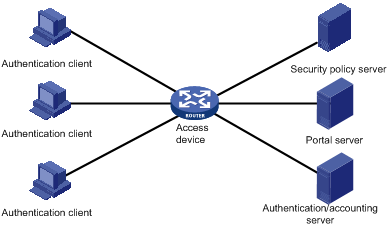
Authentication client
Client system of a user to be authenticated. It can be a browser using the Hypertext Transfer Protocol (HTTP), or a host running the portal client software. The security authentication of a client depends on the communications between the portal client and the security policy server.
Access device
Device for broadband access. It can be a switch or a router that provides the following three functions:
l Before authentication, redirecting all HTTP requests from users in the subnet to be authenticated to the portal server.
l During authentication, interacting with the portal server, security policy server and the authentication/accounting server for identity authentication, security authentication and accounting.
l After authentication, allowing users to access granted Internet resources.
Portal server
Server that listens to authentication requests from portal clients and exchanges client authentication information with the access device. It provides free portal services and a web-based authentication interface.
Authentication/accounting server
Server that implements user authentication and accounting through interaction with the access device.
Security policy server
Server that interacts with portal clients and access devices for security authentication and resource authorization.
The above five components interact in the following procedure:
1) When an unauthenticated user enters a website address in the address bar of the IE to access the Internet, an HTTP request is created and sent to the access device, which redirects the HTTP request to the web authentication homepage of the portal server.
2) On the authentication homepage/authentication dialog box, the user enters and submits the authentication information, which the portal server then transfers to the access device.
3) Upon receipt of the authentication information, the access device communicates with the authentication/accounting server for authentication and accounting.
4) After successful authentication, the access device checks whether there is corresponding security policy for the user. If not, it allows the user to access the Internet. Otherwise, the client, the access device and the security policy server communicates to perform security authentication of the user, and the security policy server authorizes the user to access resources depending on the security authentication result.
![]()
l Since a portal client uses an IP address as its ID, ensure that there is no Network Address Translation (NAT) device between the authentication client, access device, portal server, and authentication/accounting server when deploying portal authentication. This is to avoid authentication failure due to NAT operations.
l Currently, only a RADIUS server can serve as the authentication/accounting server in a portal system.
l Currently, security authentication requires the cooperation of the H3C iNode client.
Portal Authentication Modes
Portal authentication supports two modes: non-Layer 3 authentication and Layer 3 authentication.
Non-Layer 3 authentication
Non-Layer 3 authentication falls into two categories: direct authentication and Re-DHCP authentication.
l Direct authentication
Before authentication, a user manually configures a public IP address or directly obtains a public IP address through DHCP, and can access only the portal server and predefined free websites. After passing authentication, the user can access the Internet. The process of direct authentication is simpler than that of re-DHCP authentication.
l Re-DHCP authentication
Before authentication, a user gets a private IP address through DHCP and can access only the portal server and predefined free websites. After passing authentication, the user is allocated a public IP address and can access the Internet. No public IP address is allocated to those who fails authentication. This solves the problem about IP address planning and allocation and proves to be useful. For example, a service provider can allocate public IP addresses to broadband users only when they access networks beyond the residential community network.
![]()
The embedded portal server function does not support re-DHCP authentication.
Layer 3 authentication
Layer 3 portal authentication is similar to direct authentication. However, in Layer-3 portal authentication mode, a Layer 3 forwarding device can be present between the authentication client and the access device.
Differences between Layer 3 and non-Layer 3 authentication modes
l Networking mode
From this point of view, the difference between these two authentication modes lies in whether or not a Layer 3 forwarding device can be present between the authentication client and the access device. The former supports Layer 3 forwarding devices, while the latter does not.
l User identifier
In Layer 3 authentication mode, a client is uniquely identified by an IP address. This is because the mode supports Layer 3 forwarding devices between the authentication client and the access device but the access device does not learn the MAC address of the authentication client. In non-Layer 3 authentication mode, a client is uniquely identified by the combination of its IP address and MAC address because the access device can learn the MAC address of the authentication client.
Due to the above differences, when the MAC address of an authentication client remains the same but the IP address changes, a new portal authentication will be triggered in Layer-3 authentication mode but will not be triggered in non-Layer 3 authentication mode. In non-Layer 3 authentication mode, a new portal authentication will be triggered only when both the MAC and IP address of the authentication client are changed.
Portal Authentication Process
Direct authentication and Layer 3 authentication share the same authentication process, while re-DHCP authentication has a different process because of the presence of two address allocation procedures.
Direct authentication/Layer 3 authentication process
Figure 1-2 Direct authentication/Layer 3 authentication process
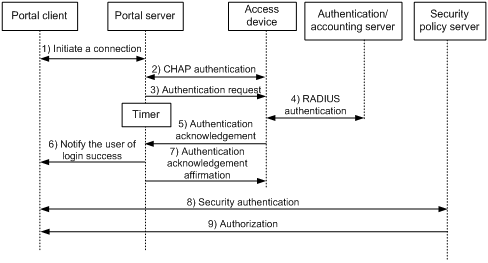
The direct authentication/Layer 3 authentication process is as follows:
1) A portal user initiates an authentication request through HTTP. When HTTP packets arrive at the access device, the access device allows those destined for the portal server or predefined free websites to pass, but redirects those destined for other websites to the portal server. The portal server provides a web page for the user to enter the username and password.
2) The portal server and the access device exchange Challenge Handshake Authentication Protocol (CHAP) messages. For Password Authentication Protocol (PAP) authentication, this step is skipped.
3) The portal server assembles the username and password into an authentication request message and sends it to the access device. Meanwhile, the portal server starts a timer to wait for an authentication acknowledgment message.
4) The access device and the RADIUS server exchange RADIUS packets to authenticate the user.
5) If the user passes authentication, the access device sends an authentication acknowledgment message to the portal server.
6) The portal server sends an authentication acknowledgment message to the authentication client to notify it of login success.
7) The portal server sends an affirmation message to the access device.
For extended portal authentication, the process includes two additional steps:
1) The security policy server exchanges security authentication information with the client to check whether the authentication client meets the security requirements.
2) The security policy server authorizes the user to access unrestricted resources based on the security configuration for the user. The authorization information is stored on the access device and used by the access device to control user access.
Re-DHCP authentication process
Figure 1-3 Re-DHCP authentication process
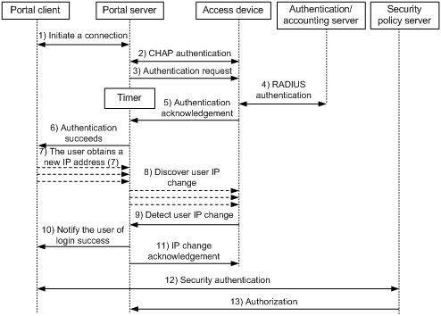
The re-DHCP authentication process is as follows:
Step 1 through step 6 are the same as those in the direct authentication/Layer 3 portal authentication process.
1) After receiving an authentication acknowledgment message, the authentication client obtains a new public IP address through DHCP and notifies the portal server that it has obtained a public IP address.
2) The portal server notifies the access device that the authentication client has obtained a new public IP address.
3) Detecting the change of the IP address by examining ARP packets received, the access device notifies the portal server of the change.
4) The portal server notifies the authentication client of login success.
5) The portal server sends a user IP address change acknowledgment message to the access device.
For extended portal authentication, the process includes two additional steps:
1) The security policy server exchanges security authentication information with the client to check whether the authentication client meets the security requirements.
2) The security policy server authorizes the user to access unrestricted resources based on the security configuration for the user. The authorization information is stored on the access device and used by the access device to take control of user access.
Authentication process with embedded portal server
Figure 1-4 Authentication process with embedded portal server
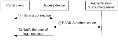
With embedded portal server, the direct/Layer 3 authentication process is as follows:
1) A portal user initiates an authentication request through HTTP. When an HTTP packet arrives at an access device interface configured with embedded portal server, the access device processes the packet based on the destination address of the packet. If the packet is destined for the Web page provided by the embedded portal server or the predefined free websites, the access device allows the packet to pass; otherwise, the device redirects the packet to the embedded portal server, which then provides a Web page for the user to enter the username and password for authentication.
2) The access device and the RADIUS server exchange RADIUS packets to authenticate the user.
3) If the user passes authentication, the embedded portal server pushes a Web page to the portal client, informing the user of the authentication (login) success.
Portal Configuration Task List
Complete these tasks to configure portal authentication:
|
Task |
Remarks |
|
Required |
|
|
Optional |
|
|
Optional |
|
|
Optional |
Basic Portal Configuration
Configuration Prerequisites
The portal feature provides a solution for user authentication and security authentication. However, the portal feature cannot implement this solution by itself. Currently, RADIUS authentication needs to be configured on the access device to cooperate with the portal feature to complete user authentication.
The prerequisites for portal authentication are as follows:
l The portal-enabled interfaces of the access device are configured with valid IP addresses or have obtained valid IP addresses through DHCP.
l The portal server and the RADIUS server have been installed and configured properly. No installation is needed for the portal server if the embedded portal server is used.
l With re-DHCP authentication, the invalid IP address check function of DHCP relay is enabled on the access device, and the DHCP server is installed and configured properly.
l With RADIUS authentication, usernames and passwords of the users are configured on the RADIUS server, and the RADIUS client configurations are performed on the access device. For information about RADIUS client configuration, refer to AAA Configuration in the Security Volume.
l To implement extended portal authentication, you need install and configure the security policy server and ensure that the ACLs configured on the access device correspond to those specified for restricted resources and unrestricted resources on the security policy server respectively. For information about security policy server configuration, refer to AAA Configuration in the Security Volume.
![]()
l For configuration about the security policy server, refer to iMC EAD Security Policy Help.
l The ACL for restricted resources and that for unrestricted resources correspond to isolation ACL and security ACL on the security policy server respectively.
l You can modify the authorized ACL on the access device. However, the new ACL takes effect only for portal users logging on after the modification.
Configuration Procedure
You can configure an external portal server or, if the device supports, an embedded portal server as needed.
l To configure an external portal server, you need to specify the IP address of the external portal server.
l To configure an embedded portal server, you need to specify the IP address of a reachable Layer 3 interface on the device as the portal server IP address.
Follow these steps to perform basic portal configuration:
|
To do… |
Use the command… |
Remarks |
|
Enter system view |
system-view |
— |
|
Configure a portal server |
portal server server-name ip ip-address [ key key-string | port port-id | url url-string ] * |
Required By default, no portal server is configured. |
|
Enter interface view |
interface interface-type interface-number |
— |
|
Enable portal authentication on the interface |
portal server server-name method { direct | layer3 | redhcp } |
Required Disabled by default |
![]()
l The destination port number that the device uses for sending packets to the portal server unsolicitedly must be the same as that the remote portal server actually uses.
l The portal server and its parameters can be deleted or modified only when the portal server is not referenced by any interface.
l The portal server to be referenced must exist.
l Only Layer 3 authentication mode can be used in applications with Layer 3 forwarding devices present between the authentication clients and the access device. However, Layer-3 authentication does not require any Layer-3 forwarding devices between the access device and the authentication clients.
l In re-DHCP authentication mode, a user is allowed to send packets using a public IP address before portal authentication, but the corresponding response packets are restricted.
l For embedded portal server configuration, the keywords port and key are not required and, if configured, will not take effect. Likewise, on an interface, the re-DHCP portal authentication mode (redhcp) can be configured but, if configured, will not take effect.
Configuring a Portal-Free Rule
A portal-free rule allows specified users to access specified external websites without portal authentication. Packets matching a portal-free rule will not trigger portal authentication and the users can directly access the specified external websites.
Follow these steps to configure a portal-free rule:
|
To do… |
Use the command… |
Remarks |
|
Enter system view |
system-view |
— |
|
Configure a portal-free rule |
portal free-rule rule-number { destination { any | ip { ip-address mask { mask-length | netmask } | any } } | source { any | [ interface interface-type interface-number | ip { ip-address mask { mask-length | mask } | any } | mac mac-address | vlan vlan-id ] * } } * |
Required |
![]()
l If you specify both a VLAN and an interface in a portal-free rule, the interface must belong to the VLAN.
l You cannot configure two or more portal-free rules with the same filtering conditions. Otherwise, the system prompts that the rule already exists.
l No matter whether portal authentication is enabled, you can only add or remove a portal-free rule, rather than modifying it.
Configuring an Authentication Subnet
By configuring authentication subnets, you specify that only packets from users on the authentication subnets trigger portal authentication. Packets that are neither from portal-free users nor from authentication subnets are discarded.
Follow these steps to configure an authentication subnet:
|
To do… |
Use the command… |
Remarks |
|
Enter system view |
system-view |
— |
|
Enter interface view |
interface interface-type interface-number |
— |
|
Configure an authentication subnet |
portal auth-network network-address { mask-length | mask } |
Optional By default, the authentication subnet is 0.0.0.0/0, which means that users with any source IP addresses are to be authenticated. |
![]()
l Configuration of authentication subnets applies to only Layer 3 portal authentication.
l In direct authentication mode, the authentication subnet is 0.0.0.0/0.
l In re-DHCP authentication mode, the authentication subnet of an interface is the subnet to which the private IP address of the interface belongs.
Logging out Users
Logging out a user terminates the authentication process for the user or removes the user.
Follow these steps to log out users:
|
To do… |
Use the command… |
Remarks |
|
Enter system view |
system-view |
— |
|
Log out users |
portal delete-user { ip-address | all | interface interface-type interface-number } |
Required |
Displaying and Maintaining Portal
|
To do… |
Use the command… |
Remarks |
|
Display the ACLs on a specified interface |
display portal acl { all | dynamic | static } interface interface-type interface-number |
Available in any view |
|
Display portal connection statistics on a specified interface or all interfaces |
display portal connection statistics { all | interface interface-type interface-number } |
Available in any view |
|
Display information about a portal-free rule or all portal-free rules |
display portal free-rule [ rule-number ] |
Available in any view |
|
Display the portal configuration of a specified interface |
display portal interface interface-type interface-number |
Available in any view |
|
Display information about a specified portal server or all portal servers |
display portal server [ server-name ] |
Available in any view |
|
Display portal server statistics on a specified interface or all interfaces |
display portal server statistics { all | interface interface-type interface-number } |
Available in any view |
|
Display TCP spoofing statistics |
display portal tcp-cheat statistics |
Available in any view |
|
Display information about portal users on a specified interface or all interfaces |
display portal user { all | interface interface-type interface-number } |
Available in any view |
|
Clear portal connection statistics on a specified interface or all interfaces |
reset portal connection statistics {all | interface interface-type interface-number } |
Available in user view |
|
Clear portal server statistics on a specified interface or all interfaces |
reset portal server statistics { all | interface interface-type interface-number } |
Available in user view |
|
Clear TCP spoofing statistics |
reset portal tcp-cheat statistics |
Available in user view |
Portal Configuration Examples
Example for Configuring Direct Portal Authentication
Network requirements
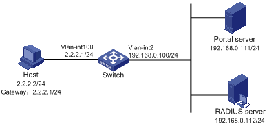
l The host is directly connected to the switch and the switch is configured for direct authentication. The host is assigned with a public network IP address manually or automatically by a DHCP server. Before portal authentication, users using the host can access only the portal server. After passing portal authentication, they can access unrestricted Internet resources.
l A RADIUS server serves as the authentication/accounting server.
Network diagram
Figure 1-5 Configure direct portal authentication
Configuration procedure
![]()
You need to configure IP addresses for the devices as shown in Figure 1-5 and ensure that routes are available between devices.
Configure the switch:
1) Configure a RADIUS scheme
# Create a RADIUS scheme named rs1 and enter its view.
<Switch> system-view
[Switch] radius scheme rs1
# Set the server type to extended.
[Switch-radius-rs1] server-type extended
# Configure the primary authentication server, the primary accounting server, and the keys for the servers to communicate.
[Switch-radius-rs1] primary authentication 192.168.0.112
[Switch-radius-rs1] primary accounting 192.168.0.112
[Switch-radius-rs1] key authentication radius
[Switch-radius-rs1] key accounting radius
# Specify that the ISP domain name should not be included in the username sent to the RADIUS server.
[Switch-radius-rs1] user-name-format without-domain
[Switch-radius-rs1] quit
2) Configure an authentication domain
# Create an ISP domain named dm1 and enter its view.
[Switch] domain dm1
# Configure the ISP domain to use RADIUS scheme rs1.
[Switch-isp-dm1] authentication portal radius-scheme rs1
[Switch-isp-dm1] authorization portal radius-scheme rs1
[Switch-isp-dm1] accounting portal radius-scheme rs1
[Switch-isp-dm1] quit
# Configure dm1 as the default ISP domain, allowing all users to share the authentication and accounting modes of the default domain.
[Switch] domain default enable dm1
3) Configure portal authentication
# Configure the portal server as follows:
l Name: newpt
l IP address: 192.168.0.111
l Key: portal
l Port number: 50100
l URL: http://192.168.0.111/portal.
[Switch] portal server newpt ip 192.168.0.111 key portal port 50100 url http://192.168.0.111/portal
# Enable portal authentication on the interface connecting the host.
[Switch] interface vlan-interface 100
[Switch–Vlan-interface100] ip address 2.2.2.1 255.255.255.0
[Switch–Vlan-interface100] portal server newpt method direct
[Switch] quit
# Configure the IP address of the interface connected with the portal server.
[Switch] interface vlan-interface 2
[Switch–Vlan-interface2] ip address 192.168.0.100 255.255.255.0
[Switch–Vlan-interface2] quit
Example for Configuring Re-DHCP Portal Authentication
Network requirements
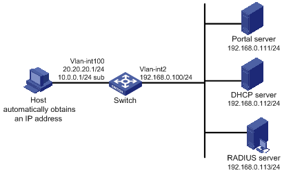
l The host is directly connected to the switch and the switch is configured for re-DHCP authentication. The host is assigned with an IP address through the DHCP server. Before portal authentication, the host uses an assigned private IP address. After passing portal authentication, it can get a public IP address and then users using the host can access unrestricted Internet resources.
l A RADIUS server serves as the authentication/accounting server.
Network diagram
Figure 1-6 Configure re-DHCP portal authentication
Configuration procedure
![]()
l For re-DHCP authentication, you need to configure a public address pool (20.20.20.0/24, in this example) and a private address pool (10.0.0.0/24, in this example) on the DHCP server. The configuration steps are omitted. For DHCP configuration information, refer to DHCP Configuration in the IP Services Volume.
l For re-DHCP authentication, the switch must be configured as a DHCP relay agent (instead of a DHCP server) and the portal-enabled interface must be configured with a primary IP address (a public IP address) and a secondary IP address (a private IP address).
l You need to configure IP addresses for the devices as shown in Figure 1-6 and ensure that routes are available between devices.
l The following describes only the configurations related to re-DHCP authentication mode. For configurations about the RADIUS scheme and ISP domain, refer to Example for Configuring Direct Portal Authentication.
Configure the switch:
#Configure the portal server as follows:
l Name: newpt
l IP address: 192.168.0.111
l Key: portal
l Port number: 50100
l URL: http://192.168.0.111/portal.
<Switch> system-view
[Switch] portal server newpt ip 192.168.0.111 key portal port 50100 url http://192.168.0.111/portal
# Configure the switch as a DHCP relay agent, and enable the invalid address check function.
[Switch] dhcp enable
[Switch] dhcp relay server-group 0 ip 192.168.0.112
[Switch] interface vlan-interface 100
[Switch–Vlan-interface100] ip address 20.20.20.1 255.255.255.0
[Switch–Vlan-interface100] ip address 10.0.0.1 255.255.255.0 sub
[Switch-Vlan-interface100] dhcp select relay
[Switch-Vlan-interface100] dhcp relay server-select 0
[Switch-Vlan-interface100] dhcp relay address-check enable
# Enable re-DHCP portal authentication on the interface connecting the host.
[Switch–Vlan-interface100] portal server newpt method redhcp
[Switch–Vlan-interface100] quit
# Configure the IP address of the interface connected with the portal server.
[Switch] interface vlan-interface 2
[Switch–Vlan-interface2] ip address 192.168.0.100 255.255.255.0
[Switch–Vlan-interface2] quit
Example for Configuring Layer 3 Portal Authentication
Network requirements
l Switch A is configured for Layer 3 portal authentication. Before portal authentication, users can access only the portal server. After passing portal authentication, they can access unrestricted Internet resources.
l The host accesses Switch A through Switch B
l A RADIUS server serves as the authentication/accounting server.
Network diagram
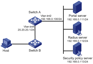
Figure 1-7 Configure Layer 3 portal authentication

Configuration procedure
![]()
l You need to configure IP addresses for the devices as shown in Figure 1-7 and ensure that routes are available between devices.
l The following describes only the major configurations related to Layer 3 portal authentication. For configurations about the RADIUS scheme and ISP domain, refer to Example for Configuring Direct Portal Authentication.
Configure Switch A:
# Configure the portal server as follows:
l Name: newpt
l IP address: 192.168.0.111
l Key: portal
l Port number: 50100
l URL: http://192.168.0.111/portal.
<SwitchA> system-view
[SwitchA] portal server newpt ip 192.168.0.111 key portal port 50100 url http://192.168.0.111/portal
# Enable portal authentication on the interface connecting Switch B.
[SwitchA] interface vlan-interface 4
[SwitchA–Vlan-interface4] ip address 20.20.20.1 255.255.255.0
[SwitchA–Vlan-interface4] portal server newpt method layer3
[SwitchA–Vlan-interface4] quit
# Configure the IP address of the interface connected with the portal server.
[SwitchA] interface vlan-interface 2
[SwitchA–Vlan-interface2] ip address 192.168.0.100 255.255.255.0
[SwitchA–Vlan-interface2] quit
On Switch B, you need to configure a default route to subnet 192.168.0.0/24, setting the next hop as 20.20.20.1. The configuration steps are omitted.
Example for Configuring Direct Extended Portal Authentication
Network requirements
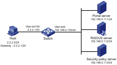
l The host is directly connected to the switch and the switch is configured for direct extended portal authentication. The host is assigned with a public network IP address manually or automatically by a DHCP server. When users using the host have passed identity authentication but have not passed security authentication, they can access only subnet 192.168.0.0/24. After passing security authentication, they can access unrestricted Internet resources.
l A RADIUS server serves as the authentication/accounting server.
Network diagram
Figure 1-8 Configure direct extended portal authentication
Configuration procedure
![]()
You need to configure IP addresses for the devices as shown in Figure 1-8 and ensure that routes are available between devices.
Configure the switch:
1) Configure a RADIUS scheme
# Create a RADIUS scheme named rs1 and enter its view.
<Switch> system-view
[Switch] radius scheme rs1
# Set the server type to extended.
[Switch-radius-rs1] server-type extended
# Configure the primary authentication server, the primary accounting server, and the keys for the servers to communicate.
[Switch-radius-rs1] primary authentication 192.168.0.112
[Switch-radius-rs1] primary accounting 192.168.0.112
[Switch-radius-rs1] key accounting radius
[Switch-radius-rs1] key authentication radius
[Switch-radius-rs1] user-name-format without-domain
# Configure the IP address of the security policy server.
[Switch-radius-rs1] security-policy-server 192.168.0.113
[Switch-radius-rs1] quit
2) Configure an authentication domain
# Create an ISP domain named dm1 and enter its view.
[Switch] domain dm1
# Configure the ISP domain to use RADIUS scheme rs1.
[Switch-isp-dm1] authentication portal radius-scheme rs1
[Switch-isp-dm1] authorization portal radius-scheme rs1
[Switch-isp-dm1] accounting portal radius-scheme rs1
[Switch-isp-dm1] quit
# Configure dm1 as the default ISP domain, allowing all users to share the authentication and accounting modes of the default domain.
[Switch] domain default enable dm1
3) Configure the ACL (ACL 3000 ) for restricted resources and the ACL (ACL 3001) for unrestricted resources
![]()
On the security policy server, you need to specify ACL 3000 as the isolation ACL and ACL 3001 as the security ACL.
[Switch] acl number 3000
[Switch-acl-adv-3000] rule permit ip destination 192.168.0.0 0.0.0.255
[Switch-acl-adv-3000] quit
[Switch] acl number 3001
[Switch-acl-adv-3001] rule permit ip
[Switch-acl-adv-3001] quit
4) Configure portal authentication
# Configure the portal server as follows:
l Name: newpt
l IP address: 192.168.0.111
l Key: portal
l Port number: 50100
l URL: http://192.168.0.111/portal.
[Switch] portal server newpt ip 192.168.0.111 key portal port 50100 url http://192.168.0.111/portal
# Enable portal authentication on the interface connecting the host.
[Switch] interface vlan-interface 100
[Switch–Vlan-interface100] ip address 2.2.2.1 255.255.255.0
[Switch–Vlan-interface100] portal server newpt method direct
[Switch] quit
# Configure the IP address of the interface connected with the portal server.
[Switch] interface vlan-interface 2
[Switch–Vlan-interface2] ip address 192.168.0.100 255.255.255.0
Example for Configuring Re-DHCP Extended Portal Authentication
Network requirements
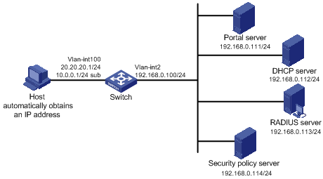
l The host is directly connected to the switch and the switch is configured for re-DHCP authentication. The host is assigned with an IP address through the DHCP server. Before portal authentication, the host uses an assigned private IP address. After passing portal authentication, it can get a public IP address.
l When users using the host have passed identity authentication but have not passed security authentication, they can access only subnet 192.168.0.0/24. After passing the security authentication, they can access unrestricted Internet resources.
l A RADIUS server serves as the authentication/accounting server.
Network diagram
Figure 1-9 Configure re-DHCP extended portal authentication
Configuration procedure
![]()
l For re-DHCP authentication, you need to configure a public address pool (20.20.20.0/24, in this example) and a private address pool (10.0.0.0/24, in this example) on the DHCP server. The configuration steps are omitted. For DHCP configuration information, refer to DHCP Configuration in the IP Services Volume.
l For re-DHCP authentication, the switch must be configured as a DHCP relay agent (instead of a DHCP server) and the portal-enabled interface must be configured with a primary IP address (a public IP address) and a secondary IP address (a private IP address).
l You need to configure IP addresses for the devices as shown in Figure 1-9 and ensure that routes are available between devices.
Configure the switch:
1) Configure a RADIUS scheme
# Create a RADIUS scheme named rs1 and enter its view.
<Switch> system-view
[Switch] radius scheme rs1
# Set the server type to extended.
[Switch-radius-rs1] server-type extended
# Configure the primary authentication server, the primary accounting server, and the keys for the servers to communicate.
[Switch-radius-rs1] primary authentication 192.168.0.113
[Switch-radius-rs1] primary accounting 192.168.0.113
[Switch-radius-rs1] key accounting radius
[Switch-radius-rs1] key authentication radius
[Switch-radius-rs1] user-name-format without-domain
# Configure the IP address of the security policy server.
[Switch-radius-rs1] security-policy-server 192.168.0.114
[Switch-radius-rs1] quit
2) Configure an authentication domain
# Create an ISP domain named dm1 and enter its view.
[Switch] domain dm1
# Configure the ISP domain to use RADIUS scheme rs1.
[Switch-isp-dm1] authentication portal radius-scheme rs1
[Switch-isp-dm1] authorization portal radius-scheme rs1
[Switch-isp-dm1] accounting portal radius-scheme rs1
[Switch-isp-dm1] quit
# Configure dm1 as the default ISP domain, allowing all users to share the authentication and accounting modes of the default domain.
[Switch] domain default enable dm1
3) Configure the ACL (ACL 3000 ) for restricted resources and the ACL (ACL 3001) for unrestricted resources
![]()
On the security policy server, you need to specify ACL 3000 as the isolation ACL and ACL 3001 as the security ACL.
[Switch] acl number 3000
[Switch-acl-adv-3000] rule permit ip destination 192.168.0.0 0.0.0.255
[Switch-acl-adv-3000] quit
[Switch] acl number 3001
[Switch-acl-adv-3001] rule permit ip
[Switch-acl-adv-3001] quit
4) Configure portal authentication
# Configure the portal server as follows:
[Switch] portal server newpt ip 192.168.0.111 key portal port 50100
url http://192.168.0.111/portal
# Configure the switch as a DHCP relay agent, and enable the invalid address check function.
[Switch] dhcp enable
[Switch] dhcp relay server-group 0 ip 192.168.0.112
[Switch] interface vlan-interface 100
[Switch–Vlan-interface100] ip address 20.20.20.1 255.255.255.0
[Switch–Vlan-interface100] ip address 10.0.0.1 255.255.255.0 sub
[Switch-Vlan-interface100] dhcp select relay
[Switch-Vlan-interface100] dhcp relay server-select 0
[Switch-Vlan-interface100] dhcp relay address-check enable
# Enable re-DHCP portal authentication on the interface connecting the host.
[Switch–Vlan-interface100] portal server newpt method redhcp
[Switch–Vlan-interface100] quit
# Configure the IP address of the interface connected with the portal server.
[Switch] interface vlan-interface 2
[Switch–Vlan-interface2] ip address 192.168.0.100 255.255.255.0
[Switch–Vlan-interface2] quit
Example for Configuring Layer 3 Extended Portal Authentication
Network requirements
l Switch A is configured for Layer 3 extended portal authentication. When users have passed identity authentication but have not passed security authentication, they can access only subnet 192.168.0.0/24. After passing security authentication, they can access unrestricted Internet resources.
l The host accesses Switch A through Switch B.
l A RADIUS server serves as the authentication/accounting server.
Network diagram
Figure 1-10 Configure Layer 3 extended portal authentication
Configuration procedure
![]()
l You need to configure IP addresses for the devices as shown in Figure 1-10 and ensure that routes are available between devices.
l The following describes only the configurations related to Layer 3 extended portal authentication. For the configurations about the RADIUS scheme, ISP domain and ACLs, refer to Example for Configuring Direct Extended Portal Authentication.
Configure the SwitchA:
1) Configure a RADIUS scheme
# Create a RADIUS scheme named rs1 and enter its view.
<SwitchA> system-view
[SwitchA] radius scheme rs1
# Set the server type to extended.
[SwitchA-radius-rs1] server-type extended
# Configure the primary authentication server, the primary accounting server, and the keys for the servers to communicate.
[SwitchA-radius-rs1] primary authentication 192.168.0.112
[SwitchA-radius-rs1] primary accounting 192.168.0.112
[SwitchA-radius-rs1] key accounting radius
[SwitchA-radius-rs1] key authentication radius
[SwitchA-radius-rs1] user-name-format without-domain
# Configure the IP address of the security policy server.
[SwitchA-radius-rs1] security-policy-server 192.168.0.113
[SwitchA-radius-rs1] quit
2) Configure an authentication domain
# Create an ISP domain named dm1 and enter its view.
[SwitchA] domain dm1
# Configure the ISP domain to use RADIUS scheme rs1.
[SwitchA-isp-dm1] authentication portal radius-scheme rs1
[SwitchA-isp-dm1] authorization portal radius-scheme rs1
[SwitchA-isp-dm1] accounting portal radius-scheme rs1
[SwitchA-isp-dm1] quit
# Configure dm1 as the default ISP domain, allowing all users to share the authentication and accounting modes of the default domain.
[SwitchA] domain default enable dm1
3) Configure the ACL (ACL 3000 ) for restricted resources and the ACL (ACL 3001) for unrestricted resources
![]()
On the security policy server, you need to specify ACL 3000 as the isolation ACL and ACL 3001 as the security ACL.
[SwitchA] acl number 3000
[SwitchA-acl-adv-3000] rule permit ip destination 192.168.0.0 0.0.0.255
[SwitchA-acl-adv-3000] quit
[SwitchA] acl number 3001
[SwitchA-acl-adv-3001] rule permit ip
[SwitchA-acl-adv-3001] quit
4) Configure portal authentication
# Configure the portal server as follows:
[SwitchA] portal server newpt ip 192.168.0.111 key portal port 50100 url http://192.168.0.111/portal
# Enable portal authentication on the interface connecting Switch B.
[SwitchA] interface vlan-interface 4
[SwitchA–Vlan-interface4] ip address 20.20.20.1 255.255.255.0
[SwitchA–Vlan-interface4] portal server newpt method layer3
[SwitchA–Vlan-interface4] quit
# Configure the IP address of the interface connected with the portal server.
[SwitchA] interface vlan-interface 2
[SwitchA–Vlan-interface2] ip address 192.168.0.100 255.255.255.0
[SwitchA–Vlan-interface2] quit
On Switch B, you need to configure a default route to subnet 192.168.0.0/24, setting the next hop as 20.20.20.1. The configuration steps are omitted.
Troubleshooting Portal
Inconsistent Keys on the Access Device and the Portal Server
Symptom
When a user is forced to access the portal server, the portal server displays neither the portal authentication page nor any error message. What the user sees is a blank web page.
Analysis
The keys configured on the access device and the portal server are inconsistent, causing CHAP message exchange failure. As a result, the portal server does not display the authentication page.
Solution
l Use the display portal server command to display the key for the portal server on the access device and view the key for the access device on the portal server.
l Use the portal server command to modify the key on the access device or modify the key for the access device on the portal server to ensure that the keys are consistent.
Incorrect Server Port Number on the Access Device
Symptom
After a user passes the portal authentication, you cannot force the user to log out by executing the portal delete-user command on the access device, but the user can log out by using the disconnect attribute on the authentication client.
Analysis
When you execute the portal delete-user command on the access device to force the user to log out, the access device actively sends a REQ_LOGOUT message to the portal server. The default listening port of the portal server is 50100. However, if the listening port configured on the access device is not 50100, the destination port of the REQ_LOGOUT message is not the actual listening port on the server. Thus, the portal server cannot receive the REQ_LOGOUT message. As a result, you cannot force the user to log out the portal server.
When the user uses the disconnect attribute on the client to log out, the portal server actively sends a REQ_LOGOUT message to the access device. The source port is 50100 and the destination port of the ACK_LOGOUT message from the access device is the source port of the REQ_LOGOUT message so that the portal server can receive the ACK_LOGOUT message correctly, no matter whether the listening port is configured on the access device. Therefore, the user can log out the portal server.
Solution
Use the display portal server command to display the listening port of the portal server on the access device and use the portal server command in the system view to modify it to ensure that it is the actual listening port of the portal server.
