- Table of Contents
- Related Documents
-
| Title | Size | Download |
|---|---|---|
| 02-802.1X Configuration | 292.41 KB |
Table of Contents
Authentication Modes of 802.1X
Authentication Process of 802.1X
Implementation of 802.1X on Devices
Features Working Together with 802.1X
Configuring an 802.1X Guest VLAN
Displaying and Maintaining 802.1X
Guest VLAN and VLAN Assignment Configuration Example
ACL Assignment Configuration Example
2 EAD Fast Deployment Configuration
EAD Fast Deployment Implementation
Configuring EAD Fast Deployment
Displaying and Maintaining EAD Fast Deployment
EAD Fast Deployment Configuration Example
Troubleshooting EAD Fast Deployment
Users Cannot be Redirected Correctly
When configuring 802.1X, go to these sections for information you are interested in:
l Configuring an 802.1X Guest VLAN
l Displaying and Maintaining 802.1X
l 802.1X Configuration Example
l Guest VLAN and VLAN Assignment Configuration Example
l ACL Assignment Configuration Example
802.1X Overview
The 802.1X protocol was proposed by IEEE802 LAN/WAN committee for security of wireless LANs (WLAN). It has been widely used on Ethernet as a common port access control mechanism.
As a port-based access control protocol, 802.1X authenticates and controls accessing devices at the port level. A device connected to an 802.1X-enabled port of an access control device can access the resources on the LAN only after passing authentication.
![]()
The port security feature provides rich security modes that combine or extend 802.1X and MAC address authentication. In a networking environment that requires flexible use of 802.1X and MAC address authentication, you are recommended to configure the port security feature. In a network environment that requires only 802.1X authentication, you are recommended to configure the 802.1X directly rather than configure the port security feature for simplicity sake. For how to use the port security feature, refer to Port Security Configuration in the Security Volume.
To get more information about 802.1X, go to these topics:
l Authentication Process of 802.1X
l Implementation of 802.1X on Devices
l Features Working Together with 802.1X
Architecture of 802.1X
802.1X operates in the typical client/server model and defines three entities: client, device, and server, as shown in Figure 1-1.
Figure 1-1 Architecture of 802.1X
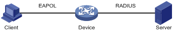
l Client: An entity to be authenticated by the device residing on the same LAN. A client is usually a user-end device and initiates 802.1X authentication through 802.1X client software supporting the EAP over LANs (EAPOL) protocol.
l Device: The entity that authenticates connected clients residing on the same LAN. A device is usually an 802.1X-enabled network device and provides ports (physical or logical) for clients to access the LAN.
l Server: The entity providing authentication, authorization, and accounting services for the device. The server usually runs the Remote Authentication Dial-in User Service (RADIUS).
Authentication Modes of 802.1X
The 802.1X authentication system employs the Extensible Authentication Protocol (EAP) to exchange authentication information between the client, device, and authentication server.
l Between the client and the device, EAP protocol packets are encapsulated using EAPOL to be transferred on the LAN.
l Between the device and the RADIUS server, EAP protocol packets can be handled in two modes: EAP relay and EAP termination. In EAP relay mode, EAP protocol packets are encapsulated in the EAP over RADIUS (EAPOR) packets on the device, which then can relay the packets to the RADIUS server. In EAP termination mode, EAP protocol packets are terminated at the device, repackaged in the Password Authentication Protocol (PAP) or Challenge Handshake Authentication Protocol (CHAP) attributes of RADIUS packets, and then transferred to the RADIUS server.
Basic Concepts of 802.1X
These basic concepts are involved in 802.1X: controlled port/uncontrolled port, authorized state/unauthorized state, and control direction.
Controlled port and uncontrolled port
A device provides ports for clients to access the LAN. Each port can be regarded as a unity of two logical ports: a controlled port and an uncontrolled port.
l The uncontrolled port is always open in both the inbound and outbound directions to allow EAPOL protocol frames to pass, guaranteeing that the client can always send and receive authentication frames.
l The controlled port is open to allow data traffic to pass only when it is in the authorized state.
l The controlled port and uncontrolled port are two parts of the same port. Any frames arriving at the port are visible to both of them.
Authorized state and unauthorized state
The device uses the authentication server to authenticate a client trying to access the LAN and controls the status of the controlled port depending on the authentication result, putting the controlled port in the authorized state or unauthorized state, as shown in Figure 1-2.
Figure 1-2 Authorized/unauthorized status of a controlled port.
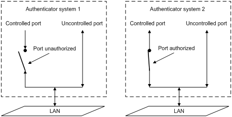
You can set the access control mode of a specified port to control the authorization status. The access control modes include:
l authorized-force: Places the port in the authorized state, allowing users of the ports to access the network without authentication.
l unauthorized-force: Places the port in the unauthorized state, denying any access requests from users of the ports.
l auto: Places the port in the unauthorized state initially to allow only EAPOL frames to pass, and turns the ports into the authorized state to allow access to the network after the users pass authentication. This is the most common choice.
Control direction
In the unauthorized state, the controlled port can be set to deny traffic to and from the client or just the traffic from the client.
![]()
Currently, your device can only be set to deny traffic from the client.
EAP over LANs
EAPOL frame format
EAPOL, defined in 802.1X, is intended to carry EAP protocol packets between clients and devices over LANs. Figure 1-3 shows the EAPOL frame format.
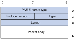
l PAE Ethernet type: Protocol type. It takes the value 0x888E.
l Protocol version: Version of the EAPOL protocol supported by the EAPOL frame sender.
l Type: Type of the EAPOL frame. Table 1-1 lists the types that the device currently supports.
Table 1-1 Types of EAPOL frames
|
Type |
Description |
|
EAP-Packet (a value of 0x00) |
Frame for carrying authentication information, present between a device and the authentication server. A frame of this type is repackaged and transferred by RADIUS to get through complex networks to reach the authentication server. |
|
EAPOL-Start (a value of 0x01) |
Frame for initiating authentication, present between a client and a device. |
|
EAPOL-Logoff (a value of 0x02) |
Frame for logoff request, present between a client and a device. |
l Length: Length of the data, that is, length of the Packet body field, in bytes. If the value of this field is 0, no subsequent data field is present.
l Packet body: Content of the packet. The format of this field varies with the value of the Type field.
EAP Packet Format
An EAPOL frame of the type of EAP-Packet carries an EAP packet in its Packet body field. The format of the EAP packet is shown in Figure 1-4.
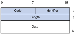
l Code: Type of the EAP packet, which can be Request, Response, Success, or Failure.
An EAP packet of the type of Success or Failure has no Data field, and has a length of 4.
An EAP packet of the type of Request or Response has a Data field in the format shown in Figure 1-5. The Type field indicates the EAP authentication type. A value of 1 represents Identity, indicating that the packet is for querying the identity of the client. A value of 4 represents MD5-Challenge, which corresponds closely to the PPP CHAP protocol.
Figure 1-5 Format of the Data field in an EAP request/response packet
![]()
l Identifier: Allows matching of responses with requests.
l Length: Length of the EAP packet, including the Code, Identifier, Length, and Data fields, in bytes.
l Data: Content of the EAP packet. This field is zero or more bytes and its format is determined by the Code field.
EAP over RADIUS
Two attributes of RADIUS are intended for supporting EAP authentication: EAP-Message and Message-Authenticator. For information about RADIUS packet format, refer to AAA Configuration in the Security Volume.
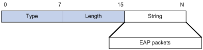
EAP-Message
The EAP-Message attribute is used to encapsulate EAP packets. Figure 1-6 shows its encapsulation format. The value of the Type field is 79. The String field can be up to 253 bytes. If the EAP packet is longer than 253 bytes, it can be fragmented and encapsulated into multiple EAP-Message attributes.
Figure 1-6 Encapsulation format of the EAP-Message attribute
Message-Authenticator
Figure 1-7 shows the encapsulation format of the Message-Authenticator attribute. The Message-Authenticator attribute is used to prevent access requests from being snooped during EAP or CHAP authentication. It must be included in any packet with the EAP-Message attribute; otherwise, the packet will be considered invalid and get discarded.
Figure 1-7 Encapsulation format of the Message-Authenticator attribute
![]()
Authentication Process of 802.1X
802.1X authentication can be initiated by either a client or the device. A client can initiate authentication by launching the 802.1X client software to send an EAPOL-Start frame to the device, while a device can initiate authentication by unsolicitedly sending an EAP-Request/Identity packet to an unauthenticated client.
An 802.1X device communicates with a remotely located RADIUS server in two modes: EAP relay and EAP termination. The following description takes the EAP relay as an example to show the 802.1X authentication process.
EAP relay
EAP relay is an IEEE 802.1X standard mode. In this mode, EAP packets are carried in an upper layer protocol, such as RADIUS, so that they can go through complex networks and reach the authentication server. Generally, EAP relay requires that the RADIUS server support the EAP attributes of EAP-Message and Message-Authenticator, which are used to encapsulate EAP packets and protect RADIUS packets carrying the EAP-Message attribute respectively.
Figure 1-8 shows the message exchange procedure with EAP-MD5.
Figure 1-8 Message exchange in EAP relay mode
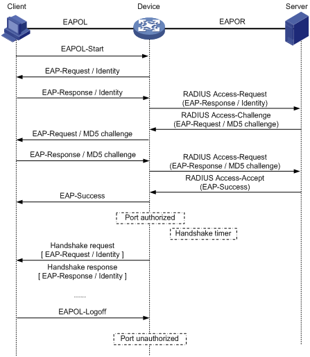
1) When a user launches the 802.1X client software and enters the registered username and password, the 802.1X client software generates an EAPOL-Start frame and sends it to the device to initiate an authentication process.
2) Upon receiving the EAPOL-Start frame, the device responds with an EAP-Request/Identity packet for the username of the client.
3) When the client receives the EAP-Request/Identity packet, it encapsulates the username in an EAP-Response/Identity packet and sends the packet to the device.
4) Upon receiving the EAP-Response/Identity packet, the device relays the packet in a RADIUS Access-Request packet to the authentication server.
5) When receiving the RADIUS Access-Request packet, the RADIUS server compares the identify information against its user information table to obtain the corresponding password information. Then, it encrypts the password information using a randomly generated challenge, and sends the challenge information through a RADIUS Access-Challenge packet to the device.
6) After receiving the RADIUS Access-Challenge packet, the device relays the contained EAP-Request/MD5 Challenge packet to the client.
7) When receiving the EAP-Request/MD5 Challenge packet, the client uses the offered challenge to encrypt the password part (this process is not reversible), creates an EAP-Response/MD5 Challenge packet, and then sends the packet to the device.
8) After receiving the EAP-Response/MD5 Challenge packet, the device relays the packet in a RADIUS Access-Request packet to the authentication server.
9) When receiving the RADIUS Access-Request packet, the RADIUS server compares the password information encapsulated in the packet with that generated by itself. If the two are identical, the authentication server considers the user valid and sends to the device a RADIUS Access-Accept packet.
10) Upon receiving the RADIUS Access-Accept packet, the device opens the port to grant the access request of the client. After the client gets online, the device periodically sends handshake requests to the client to check whether the client is still online. By default, if two consecutive handshake attempts end up with failure, the device concludes that the client has gone offline and performs the necessary operations, guaranteeing that the device always knows when a client goes offline.
![]()
In EAP relay mode, a client must use the same authentication method as that of the RADIUS server. On the device, however, you only need to execute the dot1x authentication-method eap command to enable EAP relay.
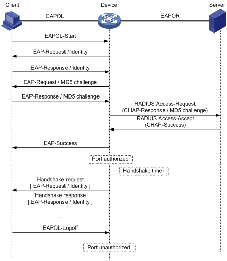
EAP termination
In EAP termination mode, EAP packets are terminated at the device and then repackaged into the PAP or CHAP attributes of RADIUS and transferred to the RADIUS server for authentication, authorization, and accounting. Figure 1-9 shows the message exchange procedure with CHAP authentication.
Figure 1-9 Message exchange in EAP termination mode
802.1X Timers
This section describes the timers used on an 802.1X device to guarantee that the client, the device, and the RADIUS server can interact with each other in a reasonable manner.
l Username request timeout timer (tx-period): The device starts this timer when it sends an EAP-Request/Identity frame to a client. If it receives no response before this timer expires, the device retransmits the request. When cooperating with a client that sends EAPOL-Start requests only when requested, the device multicasts EAP-Request/Identity frames to the client at an interval set by this timer.
l Client timeout timer (supp-timeout): Once a device sends an EAP-Request/MD5 Challenge frame to a client, it starts this timer. If this timer expires but it receives no response from the client, it retransmits the request.
l Server timeout timer (server-timeout): Once a device sends a RADIUS Access-Request packet to the authentication server, it starts this timer. If this timer expires but it receives no response from the server, it retransmits the request.
l Handshake timer (handshake-period): After a client passes authentication, the device sends to the client handshake requests at this interval to check whether the client is online. If the device receives no response after sending the allowed maximum number of handshake requests, it considers that the client is offline.
Implementation of 802.1X on Devices
The devices extend and optimize the mechanism that the 802.1X protocol specifies by:
l Allowing multiple users to access network services through the same physical port.
l Supporting two authentication methods: portbased and macbased. With the portbased method, after the first user of a port passes authentication, all other users of the port can access the network without authentication, and when the first user goes offline, all other users get offline at the same time. With the macbased method, each user of a port must be authenticated separately, and when an authenticated user goes offline, no other users are affected.
![]()
After an 802.1X client passes authentication, the authentication server sends authorization information to the device. If the authorization information contains VLAN authorization information, the device adds the port connecting the client to the assigned VLAN. This neither changes nor affects the configurations of the port. The only result is that the assigned VLAN takes precedence over the manually configured one, that is, the assigned VLAN takes effect. After the client goes offline, the configured one takes effect.
Features Working Together with 802.1X
VLAN assignment
After an 802.1X user passes the authentication, the server will send an authorization message to the device. If the server is enabled with the VLAN assignment function, the assigned VLAN information will be included in the message. The device, depending on the link type of the port used to log in, adds the port to the assigned VLAN according to the following rules:
l If the port link type is Access, the port leaves its initial VLAN, that is, the VLAN configured for it and joins the assigned VLAN.
l If the port link type is Trunk, the assigned VLAN is allowed to pass the current trunk port. The default VLAN ID of the port is that of the assigned VLAN.
l If the port link type is Hybrid, the assigned VLAN is allowed to pass the current port without carrying the tag. The default VLAN ID of the port is that of the assigned VLAN. Note that if the Hybrid port is assigned a MAC-based VLAN, the device will dynamically create a MAC-based VLAN according to the VLAN assigned by the authentication server, and remain the default VLAN ID of the port unchanged.
The assigned VLAN neither changes nor affects the configuration of a port. However, as the assigned VLAN has higher priority than the initial VLAN of the port, it is the assigned VLAN that takes effect after a user passes authentication. After the user goes offline, the port returns to the initial VLAN of the port.
For details about VLAN configuration, refer to VLAN Configuration in the Access Volume.
![]()
l With a Hybrid port, the VLAN assignment will fail if you have configured the assigned VLAN to carry tags.
l With a Hybrid port, you cannot configure an assigned VLAN to carry tags after the VLAN has been assigned.
Guest VLAN
Guest VLAN allows unauthenticated users and users failing the authentication to access a specified VLAN, where the users can, for example, download or upgrade the client software, or execute some user upgrade programs. This VLAN is called the guest VLAN.
With Guest VLAN configured on a port, if no users are successfully authenticated on the port in a certain period of time ( 90 seconds by default), the port will be added to the guest VLAN and all users accessing the port will be authorized to access the resources in the guest VLAN.
The device adds a Guest VLAN-configured port into the guest VLAN according to the port’s link type in the similar way as described in VLAN assignment. When a user of a port in the guest VLAN initiates an authentication, if the authentication is not successful, the port stays in the guest VLAN; if the authentication is successful, the port leaves the guest VLAN, and:
l If the authentication server assigns a VLAN, the port joins the assigned VLAN. After the user goes offline, the port returns to its initial VLAN, that is, the VLAN specified for it during port configuration, or, in other words, the VLAN it was in before it joined the guest VLAN.
l If the authentication server does not assign any VLAN, the port returns to its initial VLAN. After the client goes offline, the port just stays in its initial VLAN.
ACL assignment
ACLs provide a way of controlling access to network resources and defining access rights. When a user logs in through a port, and the RADIUS server is configured with authorization ACLs, the device will permit or deny data flows traversing through the port according to the authorization ACLs. Before specifying authorization ACLs on the server, you need to configure the ACL rules on the device. You can change the access rights of users by modifying authorization ACL settings on the RADIUS server or changing the corresponding ACL rules on the device.
Mandatory authentication domain for a specified port
The mandatory authentication domain function provides a security control mechanism for 802.1X access. With a mandatory authentication domain specified for a port, the system uses the mandatory authentication domain for authentication, authorization, and accounting of all 802.1X users on the port. In this way, users accessing the port cannot use any account in other domains.
Meanwhile, for EAP relay mode 802.1X authentication that uses certificates, the certificate of a user determines the authentication domain of the user. However, you can specify different mandatory authentication domains for different ports even if the user certificates are from the same certificate authority (that is, the user domain names are the same). This allows you to deploy 802.1X access policies flexibly.
Configuring 802.1X
Configuration Prerequisites
802.1X provides a user identity authentication scheme. However, 802.1X cannot implement the authentication scheme solely by itself. RADIUS or local authentication must be configured to work with 802.1X.
l Configure the ISP domain to which the 802.1X user belongs and the AAA scheme to be used (that is, local authentication or RADIUS).
l For remote RADIUS authentication, the username and password information must be configured on the RADIUS server.
l For local authentication, the username and password information must be configured on the device and the service type must be set to lan-access.
For detailed configuration of the RADIUS client, refer to AAA Configuration in the Security Volume.
Configuring 802.1X Globally
Follow these steps to configure 802.1X globally:
|
To do… |
Use the command… |
Remarks |
|
|
Enter system view |
system-view |
— |
|
|
Enable 802.1X globally |
dot1x |
Required Disabled by default |
|
|
Set the authentication method |
dot1x authentication-method { chap | eap | pap } |
Optional CHAP by default |
|
|
Set the port access control parameters |
Set the port access control mode for specified or all ports |
dot1x port-control { authorized-force | auto | unauthorized-force } [ interface interface-list ] |
Optional auto by default |
|
Set the port access control method for specified or all ports |
dot1x port-method { macbased | portbased } [ interface interface-list ] |
Optional macbased by default |
|
|
Set the maximum number of users for specified or all ports |
dot1x max-user user-number [ interface interface-list ] |
Optional 1024 by default |
|
|
Set the maximum number of attempts to send an authentication request to a client |
dot1x retry max-retry-value |
Optional 2 by default |
|
|
Set timers |
dot1x timer { handshake-period handshake-period-value | quiet-period quiet-period-value | server-timeout server-timeout-value | supp-timeout supp-timeout-value | tx-period tx-period-value } |
Optional The defaults are as follows: 15 seconds for the handshake timer, 60 seconds for the quiet timer, 100 seconds for the server timeout timer, 30 seconds for the client timeout timer, and 30 seconds for the username request timeout timer. |
|
|
Enable the quiet timer |
dot1x quiet-period |
Optional Disabled by default |
|
|
Enable detection and control of users logging in through proxies globally |
dot1x supp-proxy-check { logoff | trap } [ interface interface-list ] |
Optional Disabled by default |
|
Note that:
l For 802.1X to take effect on a port, you must enable it both globally in system view and for the port in system view or Ethernet interface view.
l You can also enable 802.1X and set port access control parameters (that is, the port access control mode, port access method, and the maximum number of users) for a port in Ethernet interface view. For detailed configuration, refer to Configuring 802.1X for a Port. The only difference between configuring 802.1X globally and configuring 802.1X for a port lies in the applicable scope. If both a global setting and a local setting exist for an argument of a port, the last configured one is in effect.
l For the 802.1X proxy detection function to take effect on a port, you need to enable the function both globally in system view and for intended ports in system view or Ethernet interface view. Besides, this function needs the cooperation of H3C 802.1X client.
l 802.1X timers only need to be changed in special or extreme network environments. For example, you can give the client timeout timer a higher value in a low-performance network, give the quiet timer a higher value in a vulnerable network or a lower value for quicker authentication response, or adjust the server timeout timer to suit the performance of the authentication server.
Configuring 802.1X for a Port
Enabling 802.1X for a port
Follow these steps to enable 802.1X for a port:
|
To do… |
Use the command… |
Remarks |
|
|
Enter system view |
system-view |
— |
|
|
Enable 802.1X for one or more ports |
In system view |
dot1x interface interface-list |
Required Use either approach. Disabled by default |
|
In Ethernet interface view |
interface interface-type interface-number |
||
|
dot1x |
|||
Configuring 802.1X parameters for a port
Follow these steps to configure 802.1X parameters for a port:
|
To do… |
Use the command… |
Remarks |
|
Enter system view |
system-view |
— |
|
Enter Ethernet interface view |
interface interface-type interface-number |
— |
|
Set the port access control mode for the port |
dot1x port-control { authorized-force | auto | unauthorized-force } |
Optional auto by default |
|
Set the port access control method for the port |
dot1x port-method { macbased | portbased } |
Optional macbased by default |
|
Set the maximum number of users for the port |
dot1x max-user user-number |
Optional 1024 by default |
|
Enable online user handshake |
dot1x handshake |
Optional Enabled by default |
|
Enable detection and control of users logging in through proxies for the port |
dot1x supp-proxy-check { logoff | trap } |
Optional Disabled by default |
|
Enable multicast trigger |
dot1x multicast-trigger |
Optional Enabled by default |
|
Specify the mandatory authentication domain for the port |
dot1x mandatory-domain domain-name |
Optional No mandatory authentication domain is specified by default. |
Note that:
l The 802.1X proxy detection function depends on the online user handshake function. Be sure to enable handshake before enabling proxy detection and to disable proxy detection before disabling handshake.
l Enabling 802.1X on a port is mutually exclusive with adding the port to an aggregation group and adding the port to a service loopback group.
l Once enabled with the 802.1X multicast trigger function, a port sends multicast trigger messages to the client periodically to initiate authentication. However, this does not happen in a wireless LAN where a client initiates authentication unsolicitedly or the wireless module finds a user and triggers authentication. You are recommended to disable the multicast trigger function in wireless LAN because the multicast trigger messages consume bandwidth.
l For a user-side device sending untagged traffic, the voice VLAN function and 802.1X are mutually exclusive and cannot be configured together on the same port. For details about voice VLAN, refer to VLAN Configuration in the Access Volume.
l In EAP relay authentication mode, the device encapsulates the 802.1X user information in the EAP attributes of RADIUS packets and sends the packets to the RADIUS server for authentication. In this case, you can configure the user-name-format command but it does not take effect. For information about the user-name-format command, refer to AAA Commands in the Security Volume.
l If the username of a client contains the version number or one or more blank spaces, you can neither retrieve information nor disconnect the client by using the username. However, you can use items such as IP address and connection index number to do so.
Configuring an 802.1X Guest VLAN
Configuration Prerequisites
l Enable 802.1X.
l Create the VLAN to be specified as the guest VLAN.
l Set the port access control method to portbased, and ensure that the 802.1X multicast trigger function is enabled.
Configuration Procedure
Follow these steps to configure Guest VLAN:
|
To do… |
Use the command… |
Remarks |
|
|
Enter system view |
system-view |
— |
|
|
Configure the guest VLAN for specified or all ports |
In system view |
dot1x guest-vlan guest-vlan-id [ interface interface-list ] |
Required Use either approach. By default, a port is configured with no guest VLAN. |
|
In Ethernet interface view |
interface interface-type interface-number |
||
|
dot1x guest-vlan vlan-id |
|||
![]()
l Different ports can be configured with different guest VLANs, but a port can be configured with only one guest VLAN.
l You cannot configure both the guest VLAN function and the free IP function in EAD fast deployment.
l A super VLAN cannot be set as the guest VLAN. Similarly, a guest VLAN cannot be set as the super VLAN. For information about super VLAN, refer to VLAN Configuration in the Access Volume.
l You can specify a tagged VLAN as the guest VLAN for a Hybrid port, but the guest VLAN does not take effect. Similarly, if a guest VLAN for a Hybrid port is in operation, you cannot configure the guest VLAN as a tagged VLAN on the port.
![]()
If the data flows from a user-side device include VLAN tags, and 802.1X and guest VLAN are enabled on the access port, you are recommended to configure different VLAN IDs for the Voice VLAN, the default port VLAN, and the guest VLAN of 802.1X.
Displaying and Maintaining 802.1X
|
To do… |
Use the command… |
Remarks |
|
Display 802.1X session information, statistics, or configuration information of specified or all ports |
display dot1x [ sessions | statistics ] [ interface interface-list ] |
Available in any view |
|
Clear 802.1X statistics |
reset dot1x statistics [ interface interface-list ] |
Available in user view |
802.1X Configuration Example
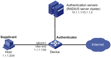
Network requirements
l The access control method of macbased is required on the port GE2/0/1 to control clients.
l All clients belong to default domain aabbcc.net, which can accommodate up to 30 users. RADIUS authentication is performed at first, and then local authentication when no response from the RADIUS server is received. If the RADIUS accounting fails, the device gets users offline.
l A server group with two RADIUS servers is connected to the device. The IP addresses of the servers are 10.1.1.1 and 10.1.1.2 respectively. Use the former as the primary authentication/secondary accounting server, and the latter as the secondary authentication/primary accounting server.
l Set the shared key for the device to exchange packets with the authentication server as name, and that for the device to exchange packets with the accounting server as money.
l Specify the device to try up to five times at an interval of 5 seconds in transmitting a packet to the RADIUS server until it receives a response from the server, and to send real time accounting packets to the accounting server every 15 minutes.
l Specify the device to remove the domain name from the username before passing the username to the RADIUS server.
l Set the username of the 802.1X user as localuser and the password as localpass and specify to use clear text mode. Enable the idle cut function to get the user offline whenever the user remains idle for over 20 minutes.
Network diagram
Figure 1-10 Network diagram for 802.1X configuration
Configuration procedure
![]()
The following configuration procedure covers most AAA/RADIUS configuration commands for the device, while configuration on the 802.1X client and RADIUS server are omitted. For information about AAA/RADIUS configuration commands, refer to AAA Configuration in the Security Volume.
# Configure the IP addresses for each interface. (Omitted)
# Add local access user localuser, enable the idle cut function, and set the idle cut interval.
<Device> system-view
[Device] local-user localuser
[Device-luser-localuser] service-type lan-access
[Device-luser-localuser] password simple localpass
[Device-luser-localuser] attribute idle-cut 20
[Device-luser-localuser] quit
# Create RADIUS scheme radius1 and enter its view.
[Device] radius scheme radius1
# Configure the IP addresses of the primary authentication and accounting RADIUS servers.
[Device-radius-radius1] primary authentication 10.1.1.1
[Device-radius-radius1] primary accounting 10.1.1.2
# Configure the IP addresses of the secondary authentication and accounting RADIUS servers.
[Device-radius-radius1] secondary authentication 10.1.1.2
[Device-radius-radius1] secondary accounting 10.1.1.1
# Specify the shared key for the device to exchange packets with the authentication server.
[Device-radius-radius1] key authentication name
# Specify the shared key for the device to exchange packets with the accounting server.
[Device-radius-radius1] key accounting money
# Set the interval for the device to retransmit packets to the RADIUS server and the maximum number of transmission attempts.
[Device-radius-radius1] timer response-timeout 5
[Device-radius-radius1] retry 5
# Set the interval for the device to send real time accounting packets to the RADIUS server.
[Device-radius-radius1] timer realtime-accounting 15
# Specify the device to remove the domain name of any username before passing the username to the RADIUS server.
[Device-radius-radius1] user-name-format without-domain
[Device-radius-radius1] quit
# Create domain aabbcc.net and enter its view.
[Device] domain aabbcc.net
# Set radius1 as the RADIUS scheme for users of the domain and specify to use local authentication as the secondary scheme.
[Device-isp-aabbcc.net] authentication default radius-scheme radius1 local
[Device-isp-aabbcc.net] authorization default radius-scheme radius1 local
[Device-isp-aabbcc.net] accounting default radius-scheme radius1 local
# Set the maximum number of users for the domain as 30.
[Device-isp-aabbcc.net] access-limit enable 30
# Enable the idle cut function and set the idle cut interval.
[Device-isp-aabbcc.net] idle-cut enable 20
[Device-isp-aabbcc.net] quit
# Configure aabbcc.net as the default domain.
[Device] domain default enable aabbcc.net
# Enable 802.1X globally.
[Device] dot1x
# Enable 802.1X for port GigabitEthernet 2/0/1.
[Device] interface GigabitEthernet 2/0/1
[Device-GigabitEthernet2/0/1] dot1x
[Device-GigabitEthernet2/0/1] quit
# Set the port access control method. (Optional. The default settings meet the requirement.)
[Device] dot1x port-method macbased interface GigabitEthernet 2/0/1
Guest VLAN and VLAN Assignment Configuration Example
Network requirements
As shown in Figure 1-11:
l A host is connected to port GigabitEthernet 2/0/2 of the device and must pass 802.1X authentication to access the Internet.
l The authentication server runs RADIUS and is in VLAN 2.
l The update server, which is in VLAN 10, is for client software download and upgrade.
l Port GigabitEthernet 2/0/3 of the device, which is in VLAN 5, is for accessing the Internet.
As shown in Figure 1-12:
l On port GigabitEthernet 2/0/2, enable 802.1X and set VLAN 10 as the guest VLAN.
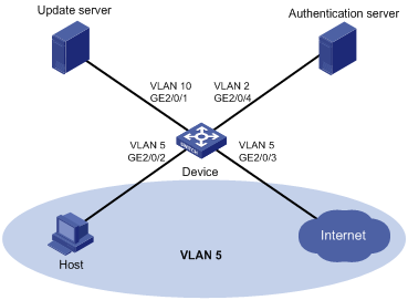
As shown in Figure 1-13:
l Authenticated clients are assigned to VLAN 5 and permitted to access the Internet.
Network diagrams
Figure 1-11 Network diagram for guest VLAN configuration
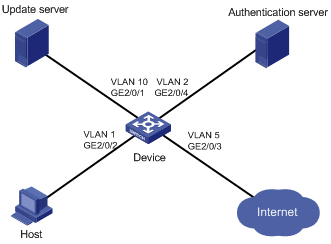
Figure 1-12 Network diagram with the port in the guest VLAN
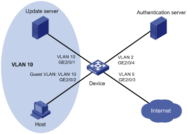
Figure 1-13 Network diagram when the client passes authentication
Configuration procedure
![]()
l The following configuration procedure uses many AAA/RADIUS commands. For detailed configuration of these commands, refer to AAA Configuration in the Security Volume.
l Configurations on the 802.1X client and RADIUS server are omitted.
# Configure RADIUS scheme 2000.
<Device> system-view
[Device] radius scheme 2000
[Device-radius-2000] primary authentication 10.11.1.1 1812
[Device-radius-2000] primary accounting 10.11.1.1 1813
[Device-radius-2000] key authentication abc
[Device-radius-2000] key accounting abc
[Device-radius-2000] user-name-format without-domain
[Device-radius-2000] quit
# Configure the default domain system and specify to use RADIUS scheme 2000 for users of the domain.
[Device] domain system
[Device-isp-system] authentication default radius-scheme 2000
[Device-isp-system] authorization default radius-scheme 2000
[Device-isp-system] accounting default radius-scheme 2000
[Device-isp-system] quit
# Enable 802.1X globally.
[Device] dot1x
# Enable 802.1X for port GigabitEthernet 2/0/2.
[Device] interface GigabitEthernet 2/0/2
[Device-GigabitEthernet2/0/2] dot1x
# Set the port access control method to portbased.
[Device-GigabitEthernet2/0/2] dot1x port-method portbased
# Set the port access control mode to auto.
[Device-GigabitEthernet2/0/2] dot1x port-control auto
[Device-GigabitEthernet2/0/2] quit
# Create VLAN 10.
[Device] vlan 10
[Device-vlan10] quit
# Specify port GigabitEthernet 2/0/2 to use VLAN 10 as its guest VLAN.
[Device] dot1x guest-vlan 10 interface GigabitEthernet 2/0/2
You can use the display current-configuration or display interface GigabitEthernet 2/0/2 command to view your configuration. You can also use the display vlan 10 command in the following cases to verify whether the configured guest VLAN functions:
l When no users log in.
l When a user fails the authentication.
l When a user goes offline.
After a user passes the authentication successfully, you can use the display interface GigabitEthernet 2/0/2 command to verity that port GigabitEthernet 2/0/2 has been added to the assigned VLAN 5.
ACL Assignment Configuration Example
Network requirements
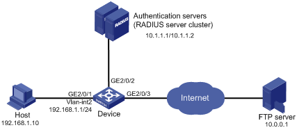
As shown in Figure 1-14, a host is connected to port GigabitEthernet 2/0/1 of the device and must pass 802.1X authentication to access the Internet.
l Configure the RADIUS server to assign ACL 3000.
l Enable 802.1X authentication on port GigabitEthernet 2/0/1 of the device, and configure ACL 3000.
After the host passes 802.1X authentication, the RADIUS server assigns ACL 3000 to port GigabitEthernet 2/0/1. As a result, the host can access the Internet but cannot access the FTP server, whose IP address is 10.0.0.1.
Network diagram
Figure 1-14 Network diagram for ACL assignment
Configuration procedure
# Configure the IP addresses of the interfaces. (Omitted)
# Configure the RADIUS scheme.
<Device> system-view
[Device] radius scheme 2000
[Device-radius-2000] primary authentication 10.1.1.1 1812
[Device-radius-2000] primary accounting 10.1.1.2 1813
[Device-radius-2000] key authentication abc
[Device-radius-2000] key accounting abc
[Device-radius-2000] user-name-format without-domain
[Device-radius-2000] quit
# Create an ISP domain and specify the AAA schemes.
[Device] domain 2000
[Device-isp-2000] authentication default radius-scheme 2000
[Device-isp-2000] authorization default radius-scheme 2000
[Device-isp-2000] accounting default radius-scheme 2000
[Device-isp-2000] quit
# Configure ACL 3000 to deny packets destined for 10.0.0.1.
[Device] acl number 3000
[Device-acl-adv-3000] rule 0 deny ip destination 10.0.0.1 0
# Enable 802.1X globally.
[Device] dot1x
# Enable 802.1X for port GigabitEthernet 2/0/1.
[Device] interface GigabitEthernet 2/0/1
[Device-GigabitEthernet2/0/1] dot1x
After logging in successfully, a user can use the ping command to verify whether the ACL 3000 assigned by the RADIUS server functions.
[Device] ping 10.0.0.1
PING 10.0.0.1: 56 data bytes, press CTRL_C to break
Request time out
Request time out
Request time out
Request time out
Request time out
--- 10.0.0.1 ping statistics ---
5 packet(s) transmitted
0 packet(s) received
100.00% packet loss
When configuring EAD fast deployment, go to these sections for information you are interested in:
l EAD Fast Deployment Overview
l Configuring EAD Fast Deployment
l Displaying and Maintaining EAD Fast Deployment
l EAD Fast Deployment Configuration Example
l Troubleshooting EAD Fast Deployment
EAD Fast Deployment Overview
Overview
Endpoint Admission Defense (EAD) is an integrated endpoint access control solution. By allowing the security clients, access devices, security policy servers, and third-party servers in the network to collaborate with each other, it can improve the overall defense capability of a network and implement centralized management of users.
Normally, to use EAD on your network, you need to manually deploy the EAD client on each device, which tends to be time consuming and inefficient. To address the issue, quick EAD deployment was developed. In conjunction with 802.1X, it can have an access switch to force all attached devices to download and install the EAD client before permitting them to access the network.
EAD Fast Deployment Implementation
To support the fast deployment of EAD schemes, 802.1X provides the following two mechanisms:
1) Limit on accessible network resources
Before successful 802.1X authentication, a user can access only specific IP segments, each of which may have one or more servers. Users can download EAD client software or obtain dynamic IP address from the servers.
2) IE URL redirection
Before successful 802.1X authentication, a user using IE to access the network is automatically redirected to a specified URL, for example, the EAD client software download page. The server that provides the URL redirection must be in the specific network segment that users can access before passing 802.1X authentication.
Configuring EAD Fast Deployment
Configuration Prerequisites
l Enable 802.1X globally.
l Enable 802.1X on the specified port, and set the access control mode to auto.
Configuration Procedure
Configuring a freely accessible network segment
A freely accessible network segment, also called a free IP, is a network segment that users can access before passing 802.1X authentication.
Once a free IP is configured, the fast deployment of EAD is enabled.
Follow these steps to configure a freely accessible network segment:
|
To do… |
Use the command… |
Remarks |
|
Enter system view |
system-view |
— |
|
Configure a freely accessible network segment |
dot1x free-ip ip-address { mask-address | mask-length } |
Required No freely accessible network segment is configured by default. |
![]()
l Currently, MAC authentication and port security cannot work together with EAD fast deployment. Once MAC authentication or port security is enabled globally, the EAD fast deployment is disabled automatically.
l You cannot configure both the free IP and the MAC authentication/802.1X guest VLAN function on a port.
l If no freely accessible network segment is configured, a user cannot obtain a dynamic IP address before passing 802.1X authentication. To solve this problem, you can configure a freely accessible network segment that is on the same network segment with the DHCP server.
Configuring the IE redirect URL
Follow these steps to configure the IE redirect URL:
|
To do… |
Use the command… |
Remarks |
|
Enter system view |
system-view |
— |
|
Configure the IE redirect URL |
dot1x url url-string |
Required No redirect URL is configured by default. |
![]()
The redirect URL and the freely accessible network segment must belong to the same network segment. Otherwise, the specified URL is unaccessible.
Setting the EAD rule timeout time
With the EAD fast deployment function, a user is authorized by an EAD rule (generally an ACL rule) to access the freely accessible network segment before passing authentication. After successful authentication, the occupied ACL will be released. If a large amount of users access the freely accessible network segment but fail the authentication, ACLs will soon be used up and new users will be rejected.
An EAD rule timeout timer is designed to solve this problem. When a user accesses the network, this timer is started. If the user neither downloads client software nor performs authentication before the timer expires, the occupied ACL will be released so that other users can use it. When there are a large number of users, you can shorten the timeout time to improve the ACL usage efficiency.
Follow these steps to set the EAD rule timeout time:
|
To do… |
Use the command… |
Remarks |
|
Enter system view |
system-view |
— |
|
Set EAD rule timeout time |
dot1x timer ead-timeout ead-timeout-value |
Optional 30 minutes by default |
Displaying and Maintaining EAD Fast Deployment
|
To do… |
Use the command… |
Remarks |
|
Display 802.1X session information, statistics, or configuration information |
display dot1x [ sessions | statistics ] [ interface interface-list ] |
Available in any view |
EAD Fast Deployment Configuration Example
Network requirements
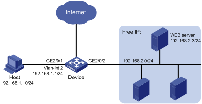
As shown in Figure 2-1, the host is connected to the device, and the device is connected to the freely accessible network segment and outside network.
It is required that:
l Before successful 802.1 authentication, the host using IE to access outside network will be redirected to the WEB server, and it can download and install 802.1X client software.
l After successful 802.1X authentication, the host can access outside network.
Network diagram
Figure 2-1 Network diagram for EAD fast deployment
Configuration procedure
1) Configure the WEB server
Before using the EAD fast deployment function, you need to configure the WEB server to provide the download service of 802.1X client software.
2) Configure the device to support EAD fast deployment
# Configure the IP addresses of the interfaces (omitted).
# Configure the free IP.
<Device> system-view
[Device] dot1x free-ip 192.168.2.0 24
# Configure the redirect URL for client software download.
[Device] dot1x url http://192.168.2.3
# Enable 802.1X globally.
[Device] dot1x
# Enable 802.1X on the port.
[Device] interface GigabitEthernet 2/0/1
[Device -GigabitEthernet2/0/1] dot1x
3) Verify your configuration
# Use the ping command to ping an IP address within the network segment specified by free IP to check that the user can access that segment before passing 802.1X authentication.
C:\>ping 192.168.2.3
Pinging 192.168.2.3 with 32 bytes of data:
Reply from 192.168.2.3: bytes=32 time<1ms TTL=128
Reply from 192.168.2.3: bytes=32 time<1ms TTL=128
Reply from 192.168.2.3: bytes=32 time<1ms TTL=128
Reply from 192.168.2.3: bytes=32 time<1ms TTL=128
Ping statistics for 192.168.2.3:
Packets: Sent = 4, Received = 4, Lost = 0 (0% loss),
Approximate round trip times in milli-seconds:
Minimum = 0ms, Maximum = 0ms, Average = 0ms
Besides, if the user uses IE to access any external website, the user will be taken to the WEB server, which provides the client software download service.
Troubleshooting EAD Fast Deployment
Users Cannot be Redirected Correctly
Symptom: When a user enters an external website address in the IE browser, the user is not redirected to the specified URL.
Analysis:
l The address is in the string format. In this case, the operating system of the host regards the string a website name and tries to have it resolved. If the resolution fails, the operating system sends an ARP request with the address in the format other than X.X.X.X. The redirection function does redirect this kind of ARP request.
l The address is within the freely accessible network segment. In this case, the device regards that the user is trying to access a host in the freely accessible network segment, and redirection will not take place, even if no host is present with the address.
l The redirect URL is not in the freely accessible network segment, no server is present with that URL, or the server with the URL does not provide WEB services.
Solution:
l Enter an IP address that is not within the freely accessible network segment in dotted decimal notation (X.X.X.X).
l Ensure that the device and the server are configured correctly.
