- Table of Contents
-
- H3C S3100 Series Ethernet Switches Operation Manual (For Soliton)(V1.02)
- 00-1Cover
- 00-2Product Overview
- 01-CLI Operation
- 02-Login Operation
- 03-Configuration File Management Operation
- 04-VLAN Operation
- 05-Management VLAN Operation
- 06-IP Address-IP Performance Operation
- 07-Voice VLAN Operation
- 08-GVRP Operation
- 09-Port Basic Configuration Operation
- 10-Link Aggregation Operation
- 11-Port Isolation Operation
- 12-Port Security-Port Binding Operation
- 13-DLDP Operation
- 14-MAC Address Table Management Operation
- 15-MSTP Operation
- 16-Multicast Operation
- 17-802.1x-System Guard Operation
- 18-AAA Operation
- 19-MAC Address Authentication Operation
- 20-ARP Operation
- 21-DHCP Operation
- 22-ACL Operation
- 23-QoS-QoS Profile Operation
- 24-Mirroring Operation
- 25-Stack-Cluster Operation
- 26-SNMP-RMON Operation
- 27-NTP Operation
- 28-SSH Operation
- 29-File System Management Operation
- 30-FTP-SFTP-TFTP Operation
- 31-Information Center Operation
- 32-System Maintenance and Debugging Operation
- 33-VLAN-VPN Operation
- 34-HWPing Operation
- 35-IPv6 Management Operation
- 36-DNS Operation
- 37-Smart Link-Monitor Link Operation
- 38-Appendix
- Related Documents
-
| Title | Size | Download |
|---|---|---|
| 25-Stack-Cluster Operation | 297.38 KB |
Table of Contents
1.1.1 The Main Switch of a Stack
1.1.2 The Slave Switches of a Stack
1.2.1 Configuring the IP Address Pool and Creating the Stack
1.2.2 Maintaining Slave Switches
1.2.3 Stack-Port Function Configuration
1.3 Slave Switch Configuration
1.4 Displaying and Debugging a Stack
1.5 Stack Configuration Example
2.2 Cluster Configuration Tasks
2.2.1 Configuring the Management Device
2.2.2 Configuring Member Devices
2.2.3 Managing a Cluster through the Management Device
2.2.4 Configuring the Enhanced Cluster Features
2.3 Displaying and Maintaining Cluster Configuration
2.4 Cluster Configuration Example
2.4.1 Basic Cluster Configuration Example
2.4.2 Enhanced Cluster Feature Configuration Example
Chapter 1 Stack
1.1 Stack Function Overview
A stack is a management domain formed by a group of Ethernet switches interconnected through their stack ports. A stack contains a main switch and multiple slave switches.
Logically, you can consider a stack a single device and manage all the switches in a stack through the main switch.
1.1.1 The Main Switch of a Stack
You can configure multiple Ethernet switches interconnected through their stack ports to form a stack by performing configurations on one of the switches. In this case, the switch becomes the main switch of the stack.
You can perform the following operations on a main switch:
l Configuring an IP address pool for the stack
l Creating the stack
l Switching to slave switch view
Before creating a stack, you need to configure an IP address pool for the stack on the main switch. When adding a switch to a stack, the main switch picks an IP address from the IP address pool and assigns the IP address to it automatically.
After a stack is created, the main switch automatically adds the switches that connected to its stack ports to the stack. If a stack port connection is disconnected, the corresponding slave switch quits the stack automatically.
1.1.2 The Slave Switches of a Stack
All the switches in a stack except the main switch are slave switches.
You can configure a slave switch in a stack on the main switch.
1.1.3 Creating a Stack
The following are the phases undergone when a stack is created.
l Connect the intended main switch and slave switches through stack modules and dedicated stack cables. (Refer to H3C S3100 Series Ethernet Switches Installation Manual for the information about stack modules and stack cables.)
l Configure the IP address pool for the stack and enable the stack function. The main switch then automatically adds the switches connected to its stack ports to the stack.
l When adding a switch joins in a stack, the main switch automatically assigns an IP address to it.
l The main switch automatically adds any switches that are newly connected to the stack through their stack ports to the stack.
1.2 Main Switch Configuration
The main switch configuration includes:
l Configuring the IP Address Pool and Creating the Stack
1.2.1 Configuring the IP Address Pool and Creating the Stack
Follow these steps to configure the IP address pool and creating the stack:
|
Operation |
Command |
Description |
|
Enter system view |
system-view |
— |
|
Configure an IP address pool for a stack |
stacking ip-pool from-ip-address ip-address-number [ ip-mask ] |
Required from-ip-address: Start address of the IP address pool. ip-address-number: Number of the IP addresses in the IP addresses pool. A pool contains 16 addresses by default. ip-mask: Mask of the IP address pool. By default, the IP addresses pool is not configured. |
|
Create a stack |
stacking enable |
Required |
& Note:
Remove the IP address configured for the existing Layer 3 interface first if you want to cancel the stack-related configuration, otherwise, IP address conflicts may occur.
As for the stack-related configurations performed on a main switch, note that:
l After a stack is created, the main switch automatically adds the switches connected to its stack ports to the stack.
l If a stack port connection is disconnected, the corresponding slave switch quits the stack automatically.
l The IP address pool of an existing stack cannot be modified.
l To add a switch to a stack successfully, make sure the IP address pool contains at least one unoccupied IP address.
l Make sure the IP addresses in the IP address pool of a stack are successive so that they can be assigned successively. For example, the IP addresses in an IP address pool with its start IP address something like 223.255.255.254 are not successive. In this case, errors may occur when adding a switch to the stack.
l IP addresses in the IP address pool of a stack must be of the same network segment. For example, the 1.1.255.254 is not a qualified start address for a stack IP address pool.
l If the IP address of the management VLAN interface of the main switch (or a slave switch) is not of the same network segment as that of the stack address pool, the main switch (or the slave switch) automatically removes the existing IP address and picks a new one from the stack address pool as its IP address.
l Since both stack and cluster use the management VLAN and only one VLAN interface is available on the S3100 switch, stack and cluster must share the same management VLAN if you want to configure stack within a cluster.
1.2.2 Maintaining Slave Switches
After creating a stack, you can switch to slave switch view from the main switch to configure slave switches.
|
Operation |
Command |
Description |
|
Switch to slave switch view |
stacking number |
Required Number: Serial number of the slave switch to be accessed. You can switch from the user view of the main switch to that of the slave switch without changing the user level. |
You can quit slave switch view after slave switch configuration.
|
Operation |
Command |
Description |
|
Quit slave switch view |
quit |
You can quit slave switch view only by executing this command in user view of a slave switch. |
1.2.3 Stack-Port Function Configuration
I. Introduction to the Stack-Port Function
If you enable the stack function on a stack-supporting device, the device will send join-in requests to the connected stack ports of all the switches connected with the device. This may cause switches not expecting to join in the stack to join in the stack automatically, affecting network stability.
You can configure the stack-port function on the stack ports that are connected with other switches to choose whether to send join-in requests to the switches, so as to prevent the switches that do not belong to the local stack from joining in.
II. Stack-Port Function Configuration
Follow these steps to configure the stack port function:
|
To do… |
Use the command… |
Remarks |
|
Enter system view |
system-view |
— |
|
Enter port view |
interface interface-type interface-number |
— |
|
Enable the stack-port function on the stack port |
stack-port enable |
Required Enabled by default. After a switch joins in a stack or becomes the master switch of a stack, the switch will send/forward stack join-in requests through this stack port. |
1.3 Slave Switch Configuration
Just make sure the slave switch is connected to the main switch through the stack ports. No configuration is needed.
1.4 Displaying and Debugging a Stack
|
Operation |
Command |
Description |
|
Display the stack status information on the main switch |
display stacking [ members ] |
Optional The display command can be executed in any view. When executed without the members keyword specified, this command displays the main switch and the number of switches in the stack. When being executed with the members keyword specified, this command displays the member information of the stack, including stack number, device name, MAC addresses and status of the main switch/slave switches. |
|
Display the stack status information on a slave switch |
display stacking |
Optional The display command can be executed in any view. The displayed information indicates that the local switch is a slave switch. The information such as stack number of the local switch, and the MAC address of the main switch in the stack is also displayed. |
1.5 Stack Configuration Example
I. Network requirements
Connect Switch A, Switch B and Switch C with each other through their stack ports to form a stack, in which Switch A acts as the main switch, while Switches B and C act as slave switches.
Configure Switches B and Switch C through Switch A.
II. Network diagram
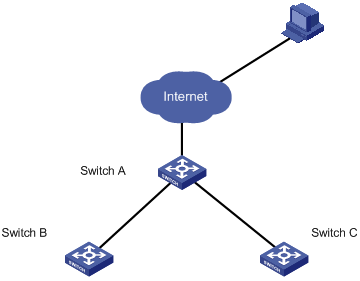
Figure 1-1 Network diagram for stack configuration
III. Configuration procedure
# Configure the IP address pool for the stack on Switch A.
<Sysname> system-view
[Sysname] stacking ip-pool 129.10.1.15 3
# Create the stack on switch A.
[Sysname] stacking enable
[stack_0.Sysname] quit
<stack_0.Sysname>
# Display the information about the stack on switch A.
<stack_0.Sysname> display stacking
Main device for stack.
Total members:3
Management-vlan:1(default vlan)
# Display the information about the stack members on switch A.
<stack_0.Sysname> display stacking members
Member number: 0
Name:stack_0.Sysname
Device: S3100
MAC Address:000f-e20f-c43a
Member status:Admin
IP: 129.10.1.15 /16
Member number: 1
Name:stack_1.Sysname
Device: S3100
MAC Address: 000f-e200-3130
Member status:Up
IP: 129.10.1.16/16
Member number: 2
Name:stack_2.Sysname
Device: S3100
MAC Address: 000f-e200-3135
Member status:Up
IP: 129.10.1.17/16
# Switch to Switch B (a slave switch).
<stack_0.Sysname> stacking 1
<stack_1.Sysname>
# Display the information about the stack on switch B.
<stack_1.Sysname> display stacking
Slave device for stack.
Member number:1
Management-vlan:1(default vlan)
Main device mac address: 000f-e20f-c43a
# Switch back to Switch A.
<stack_1.Sysname> quit
<stack_0.Sysname>
# Switch to Switch C (a slave switch).
<stack_0.Sysname> stacking 2
<stack_2.Sysname>
# Switch back to Switch A.
<stack_2.Sysname> quit
<stack_0.Sysname>
Chapter 2 Cluster
2.1 Cluster Overview
2.1.1 Introduction to HGMP
A cluster contains a group of switches. Through cluster management, you can manage multiple geographically dispersed in a centralized way.
Cluster management is implemented through Huawei group management protocol (HGMP). HGMP version 2 (HGMPv2) is used at present.
A switch in a cluster plays one of the following three roles:
l Management device
l Member device
l Candidate device
A cluster comprises of a management device and multiple member devices. To manage the devices in a cluster, you need only to configure an external IP address for the management switch. Cluster management enables you to configure and manage remote devices in batches, reducing the workload of the network configuration. Normally, there is no need to configure external IP addresses for member devices.
Figure 2-1 illustrates a cluster implementation.
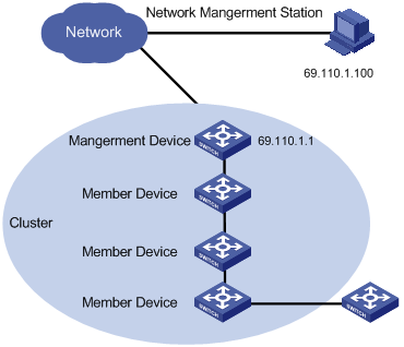
Figure 2-1 A cluster implementation
HGMP V2 has the following advantages:
l It eases the configuration and management of multiple switches: You just need to configure a public IP address for the management device instead of for all the devices in the cluster; and then you can configure and manage all the member devices through the management device without the need to log onto them one by one.
l It provides the topology discovery and display function, which assists in monitoring and maintaining the network.
l It allows you to configure and upgrade multiple switches at the same time.
l It enables you to manage your remotely devices conveniently regardless of network topology and physical distance.
l It saves IP address resource.
2.1.2 Roles in a Cluster
The switches in a cluster play different roles according to their functions and status. You can specify the role a switch plays. A switch in a cluster can also switch to other roles under specific conditions.
As mentioned above, the three cluster roles are management device, member device, and candidate device.
Table 2-1 Description on cluster roles
|
Role |
Configuration |
Function |
|
Management device |
Configured with a external IP address |
l Provides an interface for managing all the switches in a cluster l Manages member devices through command redirection, that is, it forwards the commands intended for specific member devices. l Discovers neighbors, collects the information about network topology, manages and maintains the cluster. Management device also supports FTP server and SNMP host proxy. l Processes the commands issued by users through the public network |
|
Member device |
Normally, a member device is not assigned an external IP address |
l Members of a cluster l Discovers the information about its neighbors, processes the commands forwarded by the management device, and reports log. The member devices of a luster are under the management of the management device. |
|
Candidate device |
Normally, a candidate device is not assigned an external IP address |
Candidate device refers to the devices that do not belong to any clusters but are cluster-capable. |
Figure 2-2 illustrates the state machine of cluster role.
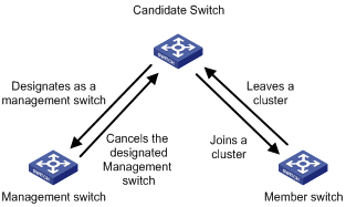
Figure 2-2 State machine of cluster role
l A candidate device becomes a management device when you create a cluster on it. Note that a cluster must have one (and only one) management device. On becoming a management device, the device collects network topology information and tries to discover and determine candidate devices, which can then be added to the cluster through configurations.
l A candidate device becomes a member device after being added to a cluster.
l A member device becomes a candidate device after it is removed from the cluster.
l A management device becomes a candidate device only after the cluster is removed.
& Note:
After you create a cluster on an S3100 switch, the switch collects the network topology information periodically and adds the candidate switches it finds to the cluster. The interval for a management device to collect network topology information is determined by the NTDP timer. If you do not want the candidate switches to be added to a cluster automatically, you can set the topology collection interval to 0 by using the ntdp timer command. In this case, the switch does not collect network topology information periodically.
2.1.3 How a Cluster Works
HGMPv2 consists of the following three protocols:
l Neighbor discovery protocol (NDP)
l Neighbor topology discovery protocol (NTDP)
l Cluster
A cluster configures and manages the devices in it through the above three protocols.
Cluster management involves topology information collection and the establishment/maintenance of a cluster. Topology information collection and cluster establishment/maintenance are independent from each other. The former, as described below, starts before a cluster is established.
l All devices use NDP to collect the information about their neighbors, including software version, host name, MAC address, and port name.
l The management device uses NTDP to collect the information about the devices within specific hops and the topology information about the devices. It also determines the candidate devices according to the information collected.
l The management device adds the candidate devices to the cluster or removes member devices from the cluster according to the candidate device information collected through NTDP.
I. Introduction to NDP
NDP is a protocol used to discover adjacent devices and provide information about them. NDP operates on the data link layer, and therefore it supports different network layer protocols.
NDP is able to discover directly connected neighbors and provide the following neighbor information: device type, software/hardware version, and connecting port. In addition, it may provide the following neighbor information: device ID, port full/half duplex mode, product version, the Boot ROM version and so on.
l An NDP-enabled device maintains an NDP neighbor table. Each entry in the NDP table can automatically ages out. You can also clear the current NDP information manually to have neighbor information collected again.
l An NDP-enabled device regularly broadcasts NDP packet through all its active ports. An NDP packet carries a holdtime field, which indicates how long the receiving devices will keep the NDP packet data. The receiving devices store the information carried in the NDP packet into the NDP table but do not forward the NDP packet. When they receive another NDP packet, if the information carried in the packet is different from the stored one, the corresponding entry in the NDP table is updated, otherwise only the holdtime of the entry is updated.
II. Introduction to NTDP
NTDP is a protocol used to collect network topology information. NTDP provides information required for cluster management: it collects topology information about the switches within the specified hop count, so as to provide the information of which devices can be added to a cluster.
Based on the neighbor information stored in the neighbor table maintained by NDP, NTDP on the management device advertises NTDP topology collection requests to collect the NDP information of each device in a specific network range as well as the connection information of all its neighbors. The information collected will be used by the management device or the network management software to implement required functions.
When a member device detects a change on its neighbors through its NDP table, it informs the management device through handshake packets, and the management device triggers its NTDP to perform specific topology collection, so that its NTDP can discover topology changes timely.
The management device collects the topology information periodically. You can also launch an operation of topology information collection by executing related commands. The process of topology information collection is as follows.
l The management device sends NTDP topology collection requests periodically through its NTDP-enabled ports.
l Upon receiving an NTDP topology collection request, the device returns a NTDP topology collection response to the management device and forwards the request to its neighbor devices through its NTDP-enable ports. The topology collection response packet contains the information about the local device and the NDP information about all the neighbor devices.
l The neighbor devices perform the same operation until the NTDP topology collection request is propagated to all the devices within the specified hops.
When an NTDP topology collection request is propagated in the network, it is received and forwarded by large numbers of network devices, which may cause network congestion and the management device busy processing of the NTDP topology collection responses. To avoid such cases, the following methods can be used to control the NTDP topology collection request advertisement speed.
l Configuring the devices not to forward the NTDP topology collection request immediately after they receive an NTDP topology collection request. That is, configure the devices to wait for a period before they forward the NTDP topology collection request.
l Configuring each NTDP-enabled port on a device to forward an NTDP topology collection request after a specific period since the previous port on the device forwards the NTDP topology collection request.
& Note:
l To implement NTDP, you need to enable NTDP both globally and on specific ports on the management device, and configure NTDP parameters.
l On member/candidate devices, you only need to enable NTDP globally and on specific ports.
l Member and candidate devices adopt the NTDP settings of the management device.
III. Introduction to Cluster
A cluster must have one and only one management device. Note the following when creating a cluster:
l You need to designate a management device for the cluster. The management device of a cluster is the portal of the cluster. That is, any operations from outside the network intended for the member devices of the cluster, such as accessing, configuring, managing, and monitoring, can only be implemented through the management device.
l The management device of the cluster recognizes and controls all the member devices in the cluster, no matter where they are located in the network and how they are connected.
l The management device collects topology information about all member/candidate devices to provide useful information for you to establish the cluster.
l By collecting NDP/NTDP information, the management device learns network topology, so as to manage and monitor network devices.
l Before performing any cluster-related configuration task, you need to enable the cluster function first.
& Note:
On the management device, you need to enable the cluster function and configure cluster parameters. On the member/candidate devices, however, you only need to enable the cluster function so that they can be managed by the management device.
IV. Cluster maintenance
1) Adding a candidate device to a cluster
To create a cluster, you need to determine the device to operate as the management device first. The management device discovers and determines candidate devices through NDP and NTDP, and adds them to the cluster. You can also add candidate devices to a cluster manually.
After a candidate device is added to a cluster, the management device assigns a member number and a private IP address (used for cluster management) to it.
2) Communications within a cluster
In a cluster, the management device maintains the connections to the member devices through handshake packets. Figure 2-3 illustrates the state machine of the connection between the management device and a member device.
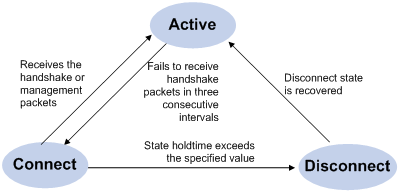
Figure 2-3 State machine of the connection between the management device and a member device
l After a cluster is created and a candidate device is added to the cluster as a member device, both the management device and the member device store the state information of the member device and mark the member device as Active.
l The management device and the member devices exchange handshake packets periodically. Note that the handshake packets exchanged keep the states of the member devices to be Active and are not responded.
l If the management device does not receive a handshake packet from a member device after a period three times of the interval to send handshake packets, it changes the state of the member device from Active to Connect. Likewise, if a member device fails to receive a handshake packet from the management device after a period three times of the interval to send handshake packets, the state of the member device will also be changed from Active to Connect.
l If the management device receives a handshake packet or management packet from a member device that is in Connect state within the information holdtime, it changes the state of the member device to Active; otherwise, it changes the state of the member device (in Connect state) to Disconnect, in which case the management device considers the member device disconnected. Likewise, if this member device, which is in Connect state, receives a handshake packet or management packet from the management device within the information holdtime, it changes its state to Active; otherwise, it changes its state to Disconnect.
l If the connection between the management device and a member device in Disconnect state is recovered, the member device will be added to the cluster again. After that, the state of the member device will turn to Active both locally and on the management device.
Besides, handshake packets are also used by member devices to inform the management device of topology changes.
Additionally, on the management device, you can configure the FTP server, TFTP server, logging host and SNMP host to be shared by the whole cluster. When a member device in the cluster communicates with an external server, the member device first transmits data to the management device, which then forwards the data to the external server. The management device serves as the default shared FTP server when no shared FTP server is configured for the cluster.
V. Management VLAN
Management VLAN limits the range of cluster management. Through management VLAN configuration, the following functions can be implemented:
l Enabling the management packets (including NDP packets, NTDP packets, and handshake packets) to be transmitted in the management VLAN only, through which the management packets are isolated from other packets and network security is improved.
l Enabling the management device and the member devices to communicate with each other in the management VLAN.
Cluster management requires the packets of the management VLAN be permitted on ports connecting the management device and the member/candidate devices. Therefore:
l If the packets of management VLAN are not permitted on a candidate device port connecting to the management device, the candidate device cannot be added to the cluster. In this case, you can enable the packets of the management VLAN to be permitted on the port through the management VLAN auto-negotiation function.
l Packets of the management VLAN can be exchanged between the management device and a member device/candidate device without carrying VLAN tags only when the default VLAN ID of both the two ports connecting the management device and the member/candidate device is the management VLAN. If the VLAN IDs of the both sides are not that of the management VLAN, packets of the management VLAN need to be tagged.
& Note:
l By default, the management VLAN interface is used as the network management interface.
l There is only one network management interface on a management device; any newly configured network management interface will overwrite the old one.
VI. Tracing a device in a cluster
In practice, you need to implement the following in a cluster sometimes:
l Know whether there is a loop in the cluster
l Locate which port on which switch initiates a network attack
l Determine the port and switch that a MAC address corresponds to
l Locate which switch in the cluster has a fault
l Check whether a link in the cluster and the devices on the link comply with the original plan
In these situations, you can use the tracemac command to trace a device in the cluster by specifying a destination MAC address or IP address.
The procedures are as follows:
1) Determine whether the destination MAC address or destination IP address is used to trace a device in the cluster
l If you use the tracemac command to trace the device by its MAC address, the switch will query its MAC address table according to the MAC address and VLAN ID in the command to find out the port connected with the downstream switch.
l If you use the tracemac command to trace the device by its IP address, the switch will query the corresponding ARP entry of the IP address to find out the corresponding MAC address and VLAN ID, and thus find out the port connected with the downstream switch.
2) After finding out the port connected with the downstream switch, the switch will send a multicast packet with the VLAN ID and specified hops to the port. Upon receiving the packet, the downstream switch compares its own MAC address with the destination MAC address carried in the multicast packet:
l If the two MAC addresses are the same, the downstream switch sends a response to the switch sending the tracemac command, indicating the success of the tracemac command.
l If the two MAC addresses are different, the downstream switch will query the port connected with its downstream switch based on the MAC address and VLAN ID, and then forward the packet to its downstream switch. If within the specified hops, a switch with the specified destination MAC address is found, this switch sends a response to the switch sending the tracemac command, indicating the success of the tracemac command. If no switch with the specified destination MAC address (or IP address) is found, the multicast packet will not be forwarded to the downstream any more.
& Note:
l If the queried IP address has a corresponding ARP entry, but the MAC address entry corresponding to the IP address does not exist, the trace of the device fails.
l To trace a specific device using the tracemac command, make sure that all the devices passed support the tracemac function.
l To trace a specific device in a management VLAN using the tracemac command, make sure that all the devices passed are within the same management VLAN as the device to be traced.
2.2 Cluster Configuration Tasks
Before configuring a cluster, you need to determine the roles and functions the switches play. You also need to configure the related functions, preparing for the communication between devices within the cluster.
Complete the following tasks to configure cluster:
|
Configuration task |
Remarks |
|
Required |
|
|
Required |
|
|
Optional |
|
|
Optional |
2.2.1 Configuring the Management Device
I. Management device configuration tasks
Complete the following tasks to configure management device:
|
Task |
Remarks |
|
Required |
|
|
Optional |
|
|
Required |
|
|
Optional |
|
|
Required |
|
|
Required |
|
|
Optional |
& Note:
To reduce the risk of being attacked by malicious users against opened socket and enhance switch security, the S3100 series Ethernet switches provide the following functions, so that a cluster socket is opened only when it is needed:
l Opening UDP port 40000 (used for cluster) only when the cluster function is implemented,
l Closing UDP port 40000 at the same time when the cluster function is closed.
On the management device, the preceding functions are implemented as follows:
l When you create a cluster by using the build or auto-build command, UDP port 40000 is opened at the same time.
l When you remove a cluster by using the undo build or undo cluster enable command, UDP port 40000 is closed at the same time.
II. Enabling NDP globally and on specific ports
Follow these steps to enable NDP globally and on specific ports:
|
Operation |
Command |
Description |
||
|
Enter system view |
system-view |
— |
||
|
Enable NDP globally |
ndp enable |
Required By default, NDP is enabled globally. |
||
|
Enable NDP on specified Ethernet ports |
In system view |
ndp enable interface port-list |
Use either approach. By default, NDP is enabled on a port. |
|
|
In Ethernet port view |
Enter Ethernet port view |
interface interface-type interface-number |
||
|
Enable NDP on the port |
ndp enable |
|||
III. Configuring NDP-related parameters
Follow these steps to configure NDP-related parameters:
|
Operation |
Command |
Description |
|
Enter system view |
system-view |
— |
|
Configure the holdtime of NDP information |
ndp timer aging aging-in-seconds |
Optional By default, the holdtime of NDP information is 180 seconds. |
|
Configure the interval to send NDP packets |
ndp timer hello seconds |
Optional By default, the interval to send NDP packets is 60 seconds. |
IV. Enabling NTDP globally and on a specific port
Follow these steps to enable NTDP globally and on a specific port:
|
Operation |
Command |
Description |
|
Enter system view |
system-view |
— |
|
Enable NTDP globally |
ntdp enable |
Required Enabled by default |
|
Enter Ethernet port view |
interface interface-type interface-number |
— |
|
Enable NTDP on the Ethernet port |
ntdp enable |
Required Enabled by default |
V. Configuring NTDP-related parameters
Follow these steps to configure NTDP-related parameters:
|
Operation |
Command |
Description |
|
Enter system view |
system-view |
— |
|
Configure the range to collect topology information |
ntdp hop hop-value |
Optional By default, the system collects topology information from the devices within three hops. |
|
Configure the device forward delay of topology collection requests |
ntdp timer hop-delay time |
Optional By default, the device forward delay is 200 ms. |
|
Configure the port forward delay of topology collection requests |
ntdp timer port-delay time |
Optional By default, the port forward delay is 20 ms. |
|
Configure the interval to collect topology information periodically |
ntdp timer interval-in-minutes |
Optional By default, the topology collection interval is one minute. |
|
Quit system view |
quit |
— |
|
Launch topology information collection manually |
ntdp explore |
Optional |
VI. Enabling the cluster function
Follow these steps to enable the cluster function:
|
Operation |
Command |
Description |
|
Enter system view |
system-view |
— |
|
Enable the cluster function globally |
cluster enable |
Required By default, the cluster function is enabled. |
VII. Configuring cluster parameters
The establishment of a cluster and the related configuration can be accomplished in manual mode or automatic mode, as described below.
1) Establishing a cluster and configuring cluster parameters in manual mode
Follow these steps to establish a cluster and configure cluster parameters in manual mode:
|
Operation |
Command |
Description |
|
Enter system view |
system-view |
— |
|
Specify the management VLAN |
management-vlan vlan-id |
Required By default, VLAN 1 is used as the management VLAN. |
|
Enter cluster view |
cluster |
— |
|
Configure a IP address pool for the cluster |
ip-pool administrator-ip-address { ip-mask | ip-mask-length } |
Required |
|
Build a cluster |
build name |
Required name: cluster name. |
|
Configure a multicast MAC address for the cluster |
cluster-mac H-H-H |
Required By default, the cluster multicast MAC address is 0180-C200-000A. |
|
Set the interval for the management device to send multicast packets |
cluster-mac syn-interval time-interval |
Optional By default, the interval to send multicast packets is one minutes. |
|
Set the holdtime of member switches |
holdtime seconds |
Optional By default, the holdtime is 60 seconds. |
|
Set the interval to send handshake packets |
timer interval |
Optional By default, the interval to send handshake packets is 10 seconds. |
2) Establish a cluster in automatic mode
Follow these steps to establish a cluster in automatic mode:
|
Operation |
Command |
Description |
|
Enter system view |
system-view |
— |
|
Enter cluster view |
cluster |
— |
|
Configure the IP address range for the cluster |
ip-pool administrator-ip-address { ip-mask | ip-mask-length } |
Required |
|
Start automatic cluster establishment |
auto-build [ recover ] |
Required Follow prompts to establish a cluster. |
& Note:
l After a cluster is established automatically, ACL 3998 and ACL 3999 will be generated automatically.
l After a cluster is established automatically, ACL 3998 and ACL 3999 can neither be modified nor removed.
VIII. Configuring inside-outside interaction for a cluster
Follow these steps to configure inside-outside interaction for a cluster:
|
Operation |
Command |
Description |
|
Enter system view |
system-view |
— |
|
Enter cluster view |
cluster |
Required |
|
Configure a shared FTP server for the cluster |
ftp-server ip-address |
Optional By default, the management device acts as the shared FTP server. |
|
Configure a shared TFTP server for the cluster |
tftp-server ip-address |
Optional By default, no shared TFTP server is configured. |
|
Configure a shared logging host for the cluster |
logging-host ip-address |
Optional By default, no shared logging host is configured. |
|
Configure a shared SNMP host for the cluster |
snmp-host ip-address |
Optional By default, no shared SNMP host is configured. |
2.2.2 Configuring Member Devices
I. Member device configuration tasks
Complete the following tasks to configure the member device:
|
Task |
Remarks |
|
Required |
|
|
Required |
|
|
Required |
|
|
Optional |
& Note:
To reduce the risk of being attacked by malicious users against opened socket and enhance switch security, the S3100 series Ethernet switches provide the following functions, so that a cluster socket is opened only when it is needed:
l Opening UDP port 40000 (used for cluster) only when the cluster function is implemented,
l Closing UDP port 40000 at the same time when the cluster function is closed.
On member devices, the preceding functions are implemented as follows:
l When you execute the add-member command on the management device to add a candidate device to a cluster, the candidate device changes to a member device and its UDP port 40000 is opened at the same time.
l When you execute the auto-build command on the management device to have the system automatically add candidate devices to a cluster, the candidate devices change to member devices and their UDP port 40000 is opened at the same time.
l When you execute the administrator-address command on a device, the device's UDP port 40000 is opened at the same time.
l When you execute the delete-member command on the management device to remove a member device from a cluster, the member device's UDP port 40000 is closed at the same time.
l When you execute the undo build command on the management device to remove a cluster, UDP port 40000 of all the member devices in the cluster is closed at the same time.
l When you execute the undo administrator-address command on a member device, UDP port 40000 of the member device is closed at the same time.
II. Enabling NDP globally and on specific ports
Follow these steps to enable NDP globally and on specific ports:
|
Operation |
Command |
Description |
||
|
Enter system view |
system-view |
— |
||
|
Enable NDP globally |
ndp enable |
Required |
||
|
Enable NDP on specified ports |
In system view |
ndp enable interface port-list |
Required Use either approach. |
|
|
In Ethernet port view |
Enter Ethernet port view |
interface interface-type interface-number |
||
|
Enable NDP on the port |
ndp enable |
|||
III. Enabling NTDP globally and on a specific port
Follow these steps to enable NTDP globally and a specific port:
|
Operation |
Command |
Description |
|
Enter system view |
system-view |
— |
|
Enable NTDP globally |
ntdp enable |
Required |
|
Enter Ethernet port view |
interface interface-type interface-number |
— |
|
Enable NTDP on the port |
ntdp enable |
Required |
IV. Enabling the cluster function
Follow these steps to enable the cluster function:
|
Operation |
Command |
Description |
|
Enter system view |
system-view |
— |
|
Enable the cluster function globally |
cluster enable |
Optional By default, the cluster function is enabled. |
V. Accessing the shared FTP/TFTP server from a member device
Follow these steps to access the shared FTP/TFTP server from a member device:
|
Operation |
Command |
Description |
|
Access the shared FTP server of the cluster |
ftp cluster |
Optional |
|
Download a file from the shared TFTP server of the cluster |
tftp cluster get source-file [ destination-file ] |
Optional |
|
Upload a file to the shared TFTP server of the cluster |
tftp cluster put source-file [ destination-file ] |
Optional |
2.2.3 Managing a Cluster through the Management Device
You can manage the member devices through the management device, for example, adding/removing a cluster member, rebooting a member device, logging into a member device, and so on.
Follow these steps to manage a cluster through management device:
|
Operation |
Command |
Description |
|
Enter system view |
system-view |
— |
|
Enter cluster view |
cluster |
— |
|
Configuring MAC address of Management device |
administrator-address mac-address name name |
Optional |
|
Add a candidate device to the cluster |
add-member [ member-number ] mac-address H-H-H [ password password ] |
Optional |
|
Remove a member device from the cluster |
delete-member member-number |
Optional |
|
Reboot a specified member device |
reboot member { member-number | mac-address H-H-H } [ eraseflash ] |
Optional |
|
Return to system view |
quit |
— |
|
Return to user view |
quit |
— |
|
Switch between management device and member device |
cluster switch-to { member-number | mac-address H-H-H | administrator } |
Optional You can use this command switch to the view of a member device and switch back. |
|
Locate device through MAC address and IP address |
tracemac { by-mac mac-address vlan vlan-id | by-ip ip-address } [ nondp ] |
Optional These commands can be executed in any view. |
2.2.4 Configuring the Enhanced Cluster Features
I. Enhanced cluster feature overview
1) Cluster topology management function
After the cluster topology becomes stable, you can use the topology management commands on the cluster administrative device to save the topology of the current cluster as the standard topology and back up the standard topology on the Flash memory of the administrative device.
When errors occur to the cluster topology, you can replace the current topology with the standard cluster topology and restore the administrative device using the backup topology on the Flash memory, so that the devices in the cluster can resume normal operation.
With the display cluster current-topology command, the switch can display the topology of the current cluster in a tree structure. The output formats include:
l Display the tree structure three layers above or below the specified node.
l Display the topology between two connected nodes.
& Note:
The topology information is saved as a topology.top file in the Flash memory to the administrative device. You cannot specify the file name manually.
2) Cluster device blacklist function
To ensure stability and security of the cluster, you can use the blacklist to restrict the devices to be added to the cluster. After you add the MAC address of the device that you need to restrict into the cluster blacklist, even if the cluster function is enabled on this device and the device is normally connected to the current cluster, this device cannot join the cluster and participate in the unified management and configuration of the cluster.
II. Configure the enhanced cluster features
Complete the following tasks to configure the enhanced cluster feature:
|
Task |
Remarks |
|
Required |
|
|
Required |
III. Configure cluster topology management function
1) Configuration prerequisites
Before configuring the cluster topology management function, make sure that:
l The basic cluster configuration is completed.
l Devices in the cluster work normally.
2) Configuration procedure
Follow these steps to configure cluster topology management function on a management device:
|
Operation |
Command |
Description |
|
Enter system view |
system-view |
— |
|
Enter cluster view |
cluster |
— |
|
Check the current topology and save it as the standard topology. |
topology accept { all [ save-to { ftp-server | local-flash } ] | mac-address mac-address | member-id member-id | administrator } |
Required |
|
Save the standard topology to the Flash memory of the administrative device |
topology save-to local-flash |
Required |
|
Restore the standard topology from the Flash memory of the administrative device |
topology restore-from local-flash |
Optional |
|
Display the detailed information about a single device |
display ntdp single-device mac-address mac-address |
Optional These commands can be executed in any view. |
|
Display the topology of the current cluster |
display cluster current-topology [ mac-address mac-address1 [ to-mac-address mac-address2 ] | member-id member-id1 [ to-member-id member-id2 ] ] |
|
|
Display the information about the base topology of the cluster |
display cluster base-topology [ mac-address mac-address | member member-id ] |
|
|
Display the information about all the devices in the base cluster topology |
display cluster base-members |
& Note:
When you display the cluster topology information, the devices attached to the switch that is listed in the backlist will not be displayed.
IV. Configure cluster device blacklist
Follow these steps to configure the cluster device blacklist on a management device:
|
Operation |
Command |
Description |
|
Enter system view |
system-view |
— |
|
Enter cluster view |
cluster |
— |
|
Add the MAC address of a specified device to the cluster blacklist |
black-list add-mac mac-address |
Optional By default, the cluster blacklist is empty. |
|
Delete the specified MAC address from the cluster blacklist |
black-list delete-mac mac-address |
Optional |
|
Delete a device from the cluster add this device to the cluster blacklist |
delete-member member-id [ to-black-list ] |
Optional |
|
Displays the information about the devices in the cluster blacklist |
display cluster black-list |
Optional This command can be executed in any view. |
2.3 Displaying and Maintaining Cluster Configuration
|
Operation |
Command |
Description |
|
Display all NDP configuration and running information (including the interval to send NDP packets, the holdtime, and all neighbors discovered) |
display ndp |
You can execute the display command in any view. |
|
Display NDP configuration and running information on specified ports (including the neighbors discovered by NDP on the ports) |
display ndp interface port-list |
|
|
Display global NTDP information |
display ntdp |
|
|
Display device information collected by NTDP |
display ntdp device-list [ verbose ] |
|
|
Display status and statistics information about the cluster |
display cluster |
|
|
Display information about the candidate devices of the cluster |
display cluster candidates [ mac-address H-H-H | verbose ] |
|
|
Display information about the member devices of the cluster |
display cluster members [ member-number | verbose ] |
|
|
Clear the statistics on NDP ports |
reset ndp statistics [ interface port-list ] |
You can execute the reset command in user view. |
& Note:
When you display the cluster topology information, the devices attached to the switch that is listed in the backlist will not be displayed.
2.4 Cluster Configuration Example
2.4.1 Basic Cluster Configuration Example
I. Network requirements
Three switches compose a cluster, where:
l An S3100 series switch serves as the management device.
l The rest are member devices.
Serving as the management device, the S3100 switch manages the two member devices. The configuration for the cluster is as follows:
l The two member devices connect to the management device through Ethernet 1/0/2 and Ethernet 1/0/3.
l The management device connects to the Internet through Ethernet 1/0/1.
l Ethernet 1/0/1 belongs to VLAN 2, whose interface IP address is 163.172.55.1.
l All the devices in the cluster share the same FTP server and TFTP server.
l The FTP server and TFTP server use the same IP address: 63.172.55.1.
l The NMS and logging host use the same IP address: 69.172.55.4.
II. Network diagram
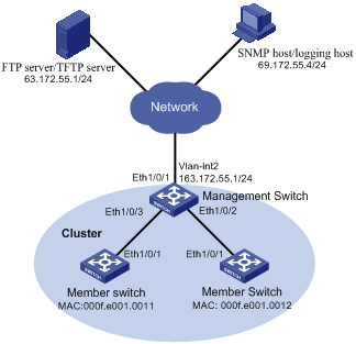
Figure 2-4 Network diagram for HGMP cluster configuration
III. Configuration procedure
1) Configure the member devices (taking one member as an example)
# Enable NDP globally and on Ethernet1/0/1.
<Sysname> system-view
[Sysname] ndp enable
[Sysname] interface Ethernet 1/0/1
[Sysname-Ethernet1/0/1] ndp enable
[Sysname-Ethernet1/0/1] quit
# Enable NTDP globally and on Ethernet1/0/1.
[Sysname] ntdp enable
[Sysname] interface Ethernet 1/0/1
[Sysname-Ethernet1/0/1] ntdp enable
[Sysname-Ethernet1/0/1] quit
# Enable the cluster function.
[Sysname] cluster enable
2) Configure the management device
# Enable NDP globally and on Ethernet 1/0/2 and Ethernet 1/0/3.
<Sysname> system-view
[Sysname] ndp enable
[Sysname] interface Ethernet 1/0/2
[Sysname-Ethernet1/0/2] ndp enable
[Sysname-Ethernet1/0/2] quit
[Sysname] interface Ethernet 1/0/3
[Sysname-Ethernet1/0/3] ndp enable
[Sysname-Ethernet1/0/3] quit
# Set the holdtime of NDP information to 200 seconds.
[Sysname] ndp timer aging 200
# Set the interval to send NDP packets to 70 seconds.
[Sysname] ndp timer hello 70
# Enable NTDP globally and on Ethernet 1/0/2 and Ethernet 1/0/3.
[Sysname] ntdp enable
[Sysname] interface Ethernet 1/0/2
[Sysname-Ethernet1/0/2] ntdp enable
[Sysname-Ethernet1/0/2] quit
[Sysname] interface Ethernet 1/0/3
[Sysname-Ethernet1/0/3] ntdp enable
[Sysname-Ethernet1/0/3] quit
# Set the topology collection range to 2 hops.
[Sysname] ntdp hop 2
# Set the member device forward delay for topology collection requests to 150 ms.
[Sysname] ntdp timer hop-delay 150
# Set the member port forward delay for topology collection requests to 15 ms.
[Sysname] ntdp timer port-delay 15
# Set the interval to collect topology information to 3 minutes.
[Sysname] ntdp timer 3
# Enable the cluster function.
[Sysname] cluster enable
# Enter cluster view.
[Sysname] cluster
[Sysname-cluster]
# Configure a private IP address pool for the cluster. The IP address pool contains six IP addresses, starting from 172.16.0.1.
[Sysname-cluster] ip-pool 172.16.0.1 255.255.255.248
# Name and build the cluster.
[Sysname-cluster] build aaa
[aaa_0.Sysname-cluster]
# Add the attached two switches to the cluster.
[aaa_0.Sysname-cluster] add-member 1 mac-address 000f-e20f-0011
[aaa_0.Sysname-cluster] add-member 17 mac-address 000f-e20f-0012
# Set the holdtime of member device information to 100 seconds.
[aaa_0.Sysname-cluster] holdtime 100
# Set the interval to send handshake packets to 10 seconds.
[aaa_0.Sysname-cluster] timer 10
# Configure the shared FTP server, TFTP server, Logging host and SNMP host for the cluster.
[aaa_0.Sysname-cluster] ftp-server 63.172.55.1
[aaa_0.Sysname-cluster] tftp-server 63.172.55.1
[aaa_0.Sysname-cluster] logging-host 69.172.55.4
[aaa_0.Sysname-cluster] snmp-host 69.172.55.4
3) Perform the following operations on the member devices (taking one member as an example)
After adding the devices under the management device to the cluster, perform the following operations on a member device.
# Connect the member device to the remote shared FTP server of the cluster.
<aaa_1.Sysname> ftp cluster
# Download the file named aaa.txt from the shared TFTP server of the cluster to the member device.
<aaa_1.Sysname> tftp cluster get aaa.txt
# Upload the file named bbb.txt from the member device to the shared TFTP server of the cluster.
<aaa_1.Sysname> tftp cluster put bbb.txt
& Note:
l After completing the above configuration, you can execute the cluster switch-to { member-number | mac-address H-H-H } command on the management device to switch to member device view to maintain and manage a member device. After that, you can execute the cluster switch-to administrator command to return to management device view.
l In addition, you can execute the reboot member { member-number | mac-address H-H-H } [ eraseflash ] command on the management device to reboot a member device. For detailed information about these operations, refer to the preceding description in this chapter.
l After the above configuration, you can receive logs and SNMP trap messages of all cluster members on the NMS.
2.4.2 Enhanced Cluster Feature Configuration Example
I. Network requirements
l The cluster operates properly.
l Add the device with the MAC address 0001-2034-a0e5 to the cluster blacklist, that is, prevent the device from being managed and maintained by the cluster.
II. Network diagram
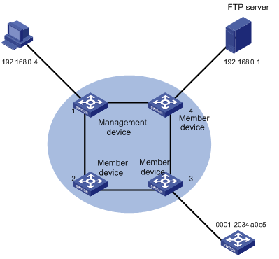
Figure 2-5 Network diagram for the enhanced cluster feature configuration
III. Configuration procedure
# Enter cluster view.
<aaa_0.Sysname> system-view
[aaa_0.Sysname] cluster
# Add the MAC address 0001-2034-a0e5 to the cluster blacklist.
[aaa_0.Sysname-cluster] black-list add-mac 0001-2034-a0e5
# Backup the current topology.
[aaa_0.Sysname-cluster] topology accept all save-to local-flash