- Table of Contents
-
- H3C S3100 Series Ethernet Switches Operation Manual (For Soliton)(V1.02)
- 00-1Cover
- 00-2Product Overview
- 01-CLI Operation
- 02-Login Operation
- 03-Configuration File Management Operation
- 04-VLAN Operation
- 05-Management VLAN Operation
- 06-IP Address-IP Performance Operation
- 07-Voice VLAN Operation
- 08-GVRP Operation
- 09-Port Basic Configuration Operation
- 10-Link Aggregation Operation
- 11-Port Isolation Operation
- 12-Port Security-Port Binding Operation
- 13-DLDP Operation
- 14-MAC Address Table Management Operation
- 15-MSTP Operation
- 16-Multicast Operation
- 17-802.1x-System Guard Operation
- 18-AAA Operation
- 19-MAC Address Authentication Operation
- 20-ARP Operation
- 21-DHCP Operation
- 22-ACL Operation
- 23-QoS-QoS Profile Operation
- 24-Mirroring Operation
- 25-Stack-Cluster Operation
- 26-SNMP-RMON Operation
- 27-NTP Operation
- 28-SSH Operation
- 29-File System Management Operation
- 30-FTP-SFTP-TFTP Operation
- 31-Information Center Operation
- 32-System Maintenance and Debugging Operation
- 33-VLAN-VPN Operation
- 34-HWPing Operation
- 35-IPv6 Management Operation
- 36-DNS Operation
- 37-Smart Link-Monitor Link Operation
- 38-Appendix
- Related Documents
-
| Title | Size | Download |
|---|---|---|
| 02-Login Operation | 486.18 KB |
Chapter 1 Logging into an Ethernet Switch
1.1 Logging into an Ethernet Switch
1.2 Introduction to the User Interface
1.2.1 Supported User Interfaces
1.2.3 Common User Interface Configuration
Chapter 2 Logging in through the Console Port
2.2 Logging in through the Console Port
2.3 Console Port Login Configuration
2.3.2 Console Port Login Configurations for Different Authentication Modes
2.4 Console Port Login Configuration with Authentication Mode Being None
2.5 Console Port Login Configuration with Authentication Mode Being Password
2.6 Console Port Login Configuration with Authentication Mode Being Scheme
Chapter 3 Logging in through Telnet
3.1.2 Telnet Configurations for Different Authentication Modes
3.2 Telnet Configuration with Authentication Mode Being None
3.3 Telnet Configuration with Authentication Mode Being Password
3.4 Telnet Configuration with Authentication Mode Being Scheme
3.5.1 Telnetting to a Switch from a Terminal
3.5.2 Telnetting to another Switch from the Current Switch
Chapter 4 Logging in Using a Modem
4.2 Configuration on the Switch Side
4.3 Modem Connection Establishment
Chapter 5 Logging in through the Web-based Network Management System
5.2 Establishing an HTTP Connection
5.3 Configuring the Login Banner
5.4 Enabling/Disabling the WEB Server
Chapter 6 Logging in through NMS
6.2 Connection Establishment Using NMS
7.2.2 Controlling Telnet Users by Source IP Addresses
7.2.3 Controlling Telnet Users by Source and Destination IP Addresses
7.2.4 Controlling Telnet Users by Source MAC Addresses
7.3 Controlling Network Management Users by Source IP Addresses
7.3.2 Controlling Network Management Users by Source IP Addresses
7.4 Controlling Web Users by Source IP Address
7.4.2 Controlling Web Users by Source IP Addresses
7.4.3 Disconnecting a Web User by Force
Chapter 1 Logging into an Ethernet Switch
1.1 Logging into an Ethernet Switch
You can log into an S3100 Ethernet switch in one of the following ways:
l Logging in locally through the Console port
l Logging in locally or remotely through an Ethernet port by means of Telnet or SSH
l Telnetting to the Console port using a modem
l Logging into the Web-based network management system
l Logging in through NMS (network management station)
1.2 Introduction to the User Interface
1.2.1 Supported User Interfaces
& Note:
The auxiliary (AUX) port and the Console port of an H3C Ethernet switch are the same port (refereed to as Console port in the following part). You will be in the AUX user interface if you log in through this port.
S3100 series Ethernet switches support two types of user interfaces: AUX and VTY.
l AUX user interface: A view when you log in through the AUX port. AUX port is a line device port.
l Virtual type terminal (VTY) user interface: A view when you log in through VTY. VTY port is a logical terminal line used when you access the device by means of Telnet or SSH.
Table 1-1 Description on user interface
|
User interface |
Applicable user |
Port used |
Description |
|
AUX |
Users logging in through the Console port |
Console port |
Each switch can accommodate one AUX user. |
|
VTY |
Telnet users and SSH users |
Ethernet port |
Each switch can accommodate up to five VTY users. |
1.2.2 User Interface Index
Two kinds of user interface index exist: absolute user interface index and relative user interface index.
1) The absolute user interface indexes are as follows:
l The absolute AUX user interfaces is numbered 0.
l VTY user interface indexes follow AUX user interface indexes. The first absolute VTY user interface is numbered 1, the second is 2, and so on.
2) A relative user interface index can be obtained by appending a number to the identifier of a user interface type. It is generated by user interface type. The relative user interface indexes are as follows:
l AUX user interfaces is numbered 0.
l VTY user interfaces are numbered VTY0, VTY1, and so on.
1.2.3 Common User Interface Configuration
Table 1-2 Common user interface configuration
|
Operation |
Command |
Description |
|
Lock the current user interface |
lock |
Optional Execute this command in user view. A user interface is not locked by default. |
|
Specify to send messages to all user interfaces/a specified user interface |
send { all | number | type number } |
Optional Execute this command in user view. |
|
Free a user interface |
free user-interface [ type ] number |
Optional Execute this command in user view. |
|
Enter system view |
system-view |
— |
|
Set the banner |
header [ incoming | legal | login | shell ] text |
Optional By default, no banner is configured |
|
Set a system name for the switch |
sysname string |
Optional By default, the system name is H3C. |
|
Enable copyright information displaying |
copyright-info enable |
Optional By default, copyright displaying is enabled. That is, the copy right information is displayed on the terminal after a user logs in successfully. |
|
Enter user interface view |
user-interface [ type ] first-number [ last-number ] |
— |
|
Display the information about the current user interface/all user interfaces |
display users [ all ] |
Optional You can execute the display command in any view. |
|
Display the physical attributes and configuration of the current/a specified user interface |
display user-interface [ type number | number ] |
|
|
Display the information about the current web users |
display web users |
Chapter 2 Logging in through the Console Port
2.1 Introduction
To log in through the Console port is the most common way to log into a switch. It is also the prerequisite to configure other login methods. By default, you can locally log into an S3100 Ethernet switch through its Console port only.
Table 2-1 lists the default settings of a Console port.
Table 2-1 The default settings of a Console port
|
Setting |
Default |
|
Baud rate |
9,600 bps |
|
Flow control |
None |
|
Check mode (Parity) |
None |
|
Stop bits |
1 |
|
Data bits |
8 |
To log into a switch through the Console port, make sure the settings of both the Console port and the user terminal are the same.
After logging into a switch, you can perform configuration for AUX users. Refer to section 2.3 “Console Port Login Configuration” for more.
2.2 Logging in through the Console Port
Following are the procedures to connect to a switch through the Console port.
1) Connect the serial port of your PC/terminal to the Console port of the switch, as shown in Figure 2-1.

Figure 2-1 Diagram for connecting to the Console port of a switch
2) If you use a PC to connect to the Console port, launch a terminal emulation utility (such as Terminal in Windows 3.X or HyperTerminal in Windows 9X/Windows 2000/Windows XP. The following assumes that you are running Windows XP) and perform the configuration shown in Figure 2-2 through Figure 2-4 for the connection to be created. Normally, both sides (that is, the serial port of the PC and the Console port of the switch) are configured as those listed in Table 2-1.

Figure 2-2 Create a connection

Figure 2-3 Specify the port used to establish the connection

Figure 2-4 Set port parameters
3) Turn on the switch. You will be prompted to press the Enter key if the switch successfully completes POST (power-on self test). The prompt (such as <H3C>) appears after you press the Enter key, as shown in Figure 2-5.

4) You can then configure the switch or check the information about the switch by executing the corresponding commands. You can also acquire help by typing the ? character. Refer to related parts in this manual for information about the commands used for configuring the switch.
2.3 Console Port Login Configuration
2.3.1 Common Configuration
Table 2-2 lists the common configuration of Console port login.
Table 2-2 Common configuration of Console port login
|
Configuration |
Remarks |
|
|
Console port configuration |
Baud rate |
Optional The default baud rate is 9,600 bps. |
|
Check mode |
Optional By default, the check mode of the Console port is set to “none”, which means no check bit. |
|
|
Stop bits |
Optional The default stop bits of a Console port is 1. |
|
|
Data bits |
Optional The default data bits of a Console port is 8. |
|
|
AUX user interface configuration |
Configure the command level available to the users logging into the AUX user interface |
Optional By default, commands of level 3 are available to the users logging into the AUX user interface. |
|
Terminal configuration |
Make terminal services available |
Optional By default, terminal services are available in all user interfaces |
|
Set the maximum number of lines the screen can contain |
Optional By default, the screen can contain up to 24 lines. |
|
|
Set history command buffer size |
Optional By default, the history command buffer can contain up to 10 commands. |
|
|
Set the timeout time of a user interface |
Optional The default timeout time is 10 minutes. |
|
![]() Caution:
Caution:
The change to Console port configuration takes effect immediately, so the connection may be disconnected when you log in through a Console port and then configure this Console port. To configure a console port, you are recommended to log into the switch in other ways. To log into a switch through its Console port after you modify the Console port settings, you need to modify the corresponding settings of the terminal emulation utility running on your PC accordingly in the dialog box shown in Figure 2-4.
2.3.2 Console Port Login Configurations for Different Authentication Modes
Table 2-3 lists Console port login configurations for different authentication modes.
Table 2-3 Console port login configurations for different authentication modes
|
Authentication mode |
Console port login configuration |
Remarks |
|
|
None |
Perform common configuration |
Perform common configuration for Console port login |
Optional Refer to Table 2-2. |
|
Password |
Configure the password |
Configure the password for local authentication |
Required |
|
Perform common configuration |
Perform common configuration for Console port login |
Optional Refer to Table 2-2. |
|
|
Scheme |
Specify to perform local authentication or remote RADIUS authentication |
AAA configuration specifies whether to perform local authentication or RADIUS authentication |
Optional Local authentication is performed by default. Refer to the AAA part for more. |
|
Configure user name and password |
Configure user names and passwords for local/RADIUS users |
Required l The user name and password of a local user are configured on the switch. l The user name and password of a RADIUS user are configured on the RADIUS server. Refer to user manual of RADIUS server for more. |
|
|
Manage AUX users |
Set service type for AUX users |
Required |
|
|
Perform common configuration |
Perform common configuration for Console port login |
Optional Refer to Table 2-2. |
|
& Note:
Changes made to the authentication mode for Console port login takes effect after you quit the command-line interface and then log in again.
2.4 Console Port Login Configuration with Authentication Mode Being None
2.4.1 Configuration Procedure
Table 2-4 Console port login configuration with the authentication mode being none
|
Operation |
Command |
Description |
|
|
Enter system view |
system-view |
— |
|
|
Enter AUX user interface view |
user-interface aux 0 |
— |
|
|
Configure not to authenticate users |
authentication-mode none |
Required By default, users logging in through the Console port (AUX user interface) are not authenticated. |
|
|
Configure the Console port |
Set the baud rate |
speed speed-value |
Optional The default baud rate of a Console port is 9,600 bps. |
|
Set the check mode |
parity { even | none | odd } |
Optional By default, the check mode of a Console port is none, that is, no check is performed. |
|
|
Set the stop bits |
stopbits { 1 | 1.5 | 2 } |
Optional The stop bits of a Console port is 1. |
|
|
Set the data bits |
databits { 7 | 8 } |
Optional The default data bits of a Console port is 8. |
|
|
Configure the command level available to users logging into the user interface |
user privilege level level |
Optional By default, commands of level 3 are available to users logging into the AUX user interface, and commands of level 0 are available to users logging into the VTY user interface. |
|
|
Enable terminal services |
shell |
Optional By default, terminal services are available in all user interfaces. |
|
|
Set the maximum number of lines the screen can contain |
screen-length screen-length |
Optional By default, the screen can contain up to 24 lines. You can use the screen-length 0 command to disable the function to display information in pages. |
|
|
Set the history command buffer size |
history-command max-size value |
Optional The default history command buffer size is 10. That is, a history command buffer can store up to 10 commands by default. |
|
|
Set the timeout time for the user interface |
idle-timeout minutes [ seconds ] |
Optional The default timeout time of a user interface is 10 minutes. With the timeout time being 10 minutes, the connection to a user interface is terminated if no operation is performed in the user interface within 10 minutes. You can use the idle-timeout 0 command to disable the timeout function. |
|
2.4.2 Configuration Example
I. Network requirements
Assume that the switch is configured to allow users to log in through Telnet, and the user level is set to the administrator level (level 3). Perform the following configurations for users logging in through the Console port (AUX user interface).
l Do not authenticate the users.
l Commands of level 2 are available to the users logging into the AUX user interface.
l The baud rate of the Console port is 19,200 bps.
l The screen can contain up to 30 lines.
l The history command buffer can contain up to 20 commands.
l The timeout time of the AUX user interface is 6 minutes.
II. Network diagram

Figure 2-6 Network diagram for AUX user interface configuration (with the authentication mode being none)
III. Configuration procedure
# Enter system view.
<Sysname> system-view
# Enter AUX user interface view.
[Sysname] user-interface aux 0
# Specify not to authenticate users logging in through the Console port.
[Sysname-ui-aux0] authentication-mode none
# Specify commands of level 2 are available to users logging into the AUX user interface.
[Sysname-ui-aux0] user privilege level 2
# Set the baud rate of the Console port to 19,200 bps.
[Sysname-ui-aux0] speed 19200
# Set the maximum number of lines the screen can contain to 30.
[Sysname-ui-aux0] screen-length 30
# Set the maximum number of commands the history command buffer can store to 20.
[Sysname-ui-aux0] history-command max-size 20
# Set the timeout time of the AUX user interface to 6 minutes.
[Sysname-ui-aux0] idle-timeout 6
After the above configuration, you need to modify the configuration of the terminal emulation utility running on the PC accordingly in the dialog box shown in Figure 2-4 to log into the switch successfully.
2.5 Console Port Login Configuration with Authentication Mode Being Password
2.5.1 Configuration Procedure
Table 2-5 Console port login configuration with the authentication mode being password
|
Operation |
Command |
Description |
|
|
Enter system view |
system-view |
— |
|
|
Enter AUX user interface view |
user-interface aux 0 |
— |
|
|
Configure to authenticate users using the local password |
authentication-mode password |
Required By default, users logging into a switch through the Console port are not authenticated; while those logging in through Modems or Telnet are authenticated. |
|
|
Set the local password |
set authentication password { cipher | simple } password |
Required |
|
|
Configure the Console port |
Set the baud rate |
speed speed-value |
Optional The default baud rate of an AUX port (also the Console port) is 9,600 bps. |
|
Set the check mode |
parity { even | none | odd } |
Optional By default, the check mode of a Console port is set to none, that is, no check bit. |
|
|
Set the stop bits |
stopbits { 1 | 1.5 | 2 } |
Optional The default stop bits of a Console port is 1. |
|
|
Set the data bits |
databits { 7 | 8 } |
Optional The default data bits of a Console port is 8. |
|
|
Configure the command level available to users logging into the user interface |
user privilege level level |
Optional By default, commands of level 3 are available to users logging into the AUX user interface. |
|
|
Make terminal services available to the user interface |
shell |
Optional By default, terminal services are available in all user interfaces. |
|
|
Set the maximum number of lines the screen can contain |
screen-length screen-length |
Optional By default, the screen can contain up to 24 lines. You can use the screen-length 0 command to disable the function to display information in pages. |
|
|
Set history command buffer size |
history-command max-size value |
Optional The default history command buffer size is 10. That is, a history command buffer can store up to 10 commands by default. |
|
|
Set the timeout time for the user interface |
idle-timeout minutes [ seconds ] |
Optional The default timeout time of a user interface is 10 minutes. With the timeout time being 10 minutes, the connection to a user interface is terminated if no operation is performed in the user interface within 10 minutes. You can use the idle-timeout 0 command to disable the timeout function. |
|
2.5.2 Configuration Example
I. Network requirements
Assume the switch is configured to allow users to log in through Telnet, and the user level is set to the administrator level (level 3). Perform the following configurations for users logging in through the Console port (AUX user interface).
l Authenticate the users using passwords.
l Set the local password to 123456 (in plain text).
l The commands of level 2 are available to the users.
l The baud rate of the Console port is 19,200 bps.
l The screen can contain up to 30 lines.
l The history command buffer can store up to 20 commands.
l The timeout time of the AUX user interface is 6 minutes.
II. Network diagram
Figure 2-7 Network diagram for AUX user interface configuration (with the authentication mode being password)
III. Configuration procedure
# Enter system view.
<Sysname> system-view
# Enter AUX user interface view.
[Sysname] user-interface aux 0
# Specify to authenticate users logging in through the Console port using the local password.
[Sysname-ui-aux0] authentication-mode password
# Set the local password to 123456 (in plain text).
[Sysname-ui-aux0] set authentication password simple 123456
# Specify commands of level 2 are available to users logging into the AUX user interface.
[Sysname-ui-aux0] user privilege level 2
# Set the baud rate of the Console port to 19,200 bps.
[Sysname-ui-aux0] speed 19200
# Set the maximum number of lines the screen can contain to 30.
[Sysname-ui-aux0] screen-length 30
# Set the maximum number of commands the history command buffer can store to 20.
[Sysname-ui-aux0] history-command max-size 20
# Set the timeout time of the AUX user interface to 6 minutes.
[Sysname-ui-aux0] idle-timeout 6
After the above configuration, you need to modify the configuration of the terminal emulation utility running on the PC accordingly in the dialog box shown in Figure 2-4 to log into the switch successfully.
2.6 Console Port Login Configuration with Authentication Mode Being Scheme
2.6.1 Configuration Procedure
Table 2-6 Console port login configuration with the authentication mode being scheme
|
Operation |
Command |
Description |
||
|
Enter system view |
system-view |
— |
||
|
Configure the authentication mode |
Enter the default ISP domain view |
domain domain-name |
Optional By default, the local AAA scheme is applied. If you specify to apply the local AAA scheme, you need to perform the configuration concerning local user as well. If you specify to apply an existing scheme by providing the radius-scheme-name argument, you need to perform the following configuration as well: l Perform AAA&RADIUS configuration on the switch. (Refer to the AAA part for more.) l Configure the user name and password accordingly on the AAA server. (Refer to the user manual of AAA server.) |
|
|
Specify the AAA scheme to be applied to the domain |
scheme { local | none | radius-scheme radius-scheme-name [ local ] | hwtacacs-scheme hwtacacs-scheme-name [ local ] } |
|||
|
Quit to system view |
quit |
|||
|
Create a local user (Enter local user view.) |
local-user user-name |
Required No local user exists by default. |
||
|
Set the authentication password for the local user |
password { simple | cipher } password |
Required |
||
|
Specify the service type for AUX users |
service-type terminal [ level level ] |
Required |
||
|
Quit to system view |
quit |
— |
||
|
Enter AUX user interface view |
user-interface aux 0 |
— |
||
|
Configure to authenticate users locally or remotely |
authentication-mode scheme [ command- authorization ] |
Required The specified AAA scheme determines whether to authenticate users locally or remotely. By default, users logging in through the Console port (AUX user interface) are not authenticated. |
||
|
Configure the Console port |
Set the baud rate |
speed speed-value |
Optional The default baud rate of the AUX port (also the Console port) is 9,600 bps. |
|
|
Set the check mode |
parity { even | none | odd } |
Optional By default, the check mode of a Console port is set to none, that is, no check bit. |
||
|
Set the stop bits |
stopbits { 1 | 1.5 | 2 } |
Optional The default stop bits of a Console port is 1. |
||
|
Set the data bits |
databits { 7 | 8 } |
Optional The default data bits of a Console port is 8. |
||
|
Configure the command level available to users logging into the user interface |
user privilege level level |
Optional By default, commands of level 3 are available to users logging into the AUX user interface. |
||
|
Make terminal services available to the user interface |
shell |
Optional By default, terminal services are available in all user interfaces. |
||
|
Set the maximum number of lines the screen can contain |
screen-length screen-length |
Optional By default, the screen can contain up to 24 lines. You can use the screen-length 0 command to disable the function to display information in pages. |
||
|
Set history command buffer size |
history-command max-size value |
Optional The default history command buffer size is 10. That is, a history command buffer can store up to 10 commands by default. |
||
|
Set the timeout time for the user interface |
idle-timeout minutes [ seconds ] |
Optional The default timeout time of a user interface is 10 minutes. With the timeout time being 10 minutes, the connection to a user interface is terminated if no operation is performed in the user interface within 10 minutes. You can use the idle-timeout 0 command to disable the timeout function. |
||
Note that if you configure to authenticate the users in the scheme mode, the command level available to users logging into a switch depends on the command level specified in the service-type terminal [ level level ] command.
2.6.2 Configuration Example
I. Network requirements
Assume the switch is configured to allow users to log in through Telnet, and the user level is set to the administrator level (level 3). Perform the following configurations for users logging in through the console port (AUX user interface).
l Configure the local user name as “guest”.
l Set the authentication password of the local user to 123456 (in plain text).
l Set the service type of the local user to Terminal and the command level to 2.
l Configure to authenticate the users in the scheme mode.
l The baud rate of the Console port is 19,200 bps.
l The screen can contain up to 30 lines.
l The history command buffer can store up to 20 commands.
l The timeout time of the AUX user interface is 6 minutes.
II. Network diagram
Figure 2-8 Network diagram for AUX user interface configuration (with the authentication mode being scheme)
III. Configuration procedure
# Enter system view.
<Sysname> system-view
# Create a local user named guest and enter local user view.
[Sysname] local-user guest
# Set the authentication password to 123456 (in plain text).
[Sysname-luser-guest] password simple 123456
# Set the service type to Terminal, Specify commands of level 2 are available to users logging into the AUX user interface.
[Sysname-luser-guest] service-type terminal level 2
[Sysname-luser-guest] quit
# Enter AUX user interface view.
[Sysname] user-interface aux 0
# Configure to authenticate users logging in through the Console port in the scheme mode.
[Sysname-ui-aux0] authentication-mode scheme
# Set the baud rate of the Console port to 19,200 bps.
[Sysname-ui-aux0] speed 19200
# Set the maximum number of lines the screen can contain to 30.
[Sysname-ui-aux0] screen-length 30
# Set the maximum number of commands the history command buffer can store to 20.
[Sysname-ui-aux0] history-command max-size 20
# Set the timeout time of the AUX user interface to 6 minutes.
[Sysname-ui-aux0] idle-timeout 6
After the above configuration, you need to modify the configuration of the terminal emulation utility running on the PC accordingly in the dialog box shown in Figure 2-4 to log into the switch successfully.
Chapter 3 Logging in through Telnet
3.1 Introduction
S3100 series Ethernet switches support Telnet. You can manage and maintain a switch remotely by Telnetting to the switch.
To log into a switch through Telnet, the corresponding configuration is required on both the switch and the Telnet terminal.
You can also log into a switch through SSH. SSH is a secure shell added to Telnet. Refer to the SSH Operation for related information.
Table 3-1 Requirements for Telnetting to a switch
|
Item |
Requirement |
|
Switch |
The IP address is configured for the VLAN of the switch, and the route between the switch and the Telnet terminal is reachable. (Refer to the IP Address Configuration – IP Performance Configuration and Routing Protocol parts for more.) |
|
The authentication mode and other settings are configured. Refer to Table 3-2 and Table 3-3. |
|
|
Telnet terminal |
Telnet is running. |
|
The IP address of the VLAN of the switch is available. |
& Note:
Telnetting to a switch using IPv6 protocols is similar to Telnetting to a switch using IPv4 protocols. Refer to the IPv6 Management part for related information.
3.1.1 Common Configuration
Table 3-2 lists the common Telnet configuration.
Table 3-2 Common Telnet configuration
|
Configuration |
Description |
|
|
VTY user interface configuration |
Configure the command level available to users logging into the VTY user interface |
Optional By default, commands of level 0 are available to users logging into a VTY user interface. |
|
Configure the protocols the user interface supports |
Optional By default, Telnet and SSH protocol are supported. |
|
|
Set the commands to be executed automatically after a user log into the user interface successfully |
Optional By default, no command is executed automatically after a user logs into the VTY user interface. |
|
|
VTY terminal configuration |
Make terminal services available |
Optional By default, terminal services are available in all user interfaces |
|
Set the maximum number of lines the screen can contain |
Optional By default, the screen can contain up to 24 lines. |
|
|
Set history command buffer size |
Optional By default, the history command buffer can contain up to 10 commands. |
|
|
Set the timeout time of a user interface |
Optional The default timeout time is 10 minutes. |
|
3.1.2 Telnet Configurations for Different Authentication Modes
Table 3-3 lists Telnet configurations for different authentication modes.
Table 3-3 Telnet configurations for different authentication modes
|
Authentication mode |
Telnet configuration |
Description |
|
|
None |
Perform common configuration |
Perform common Telnet configuration |
Optional Refer to Table 3-2. |
|
Password |
Configure the password |
Configure the password for local authentication |
Required |
|
Perform common configuration |
Perform common Telnet configuration |
Optional Refer to Table 3-2. |
|
|
Scheme |
Specify to perform local authentication or remote RADIUS authentication |
AAA configuration specifies whether to perform local authentication or RADIUS authentication |
Optional Local authentication is performed by default. Refer to the AAA part for more. |
|
Configure user name and password |
Configure user names and passwords for local/RADIUS users |
Required l The user name and password of a local user are configured on the switch. l The user name and password of a remote user are configured on the RADIUS server. Refer to user manual of RADIUS server for more. |
|
|
Manage VTY users |
Set service type for VTY users |
Required |
|
|
Perform common configuration |
Perform common Telnet configuration |
Optional Refer to Table 3-2. |
|
& Note:
To improve security and prevent attacks to the unused Sockets, TCP 23 and TCP 22, ports for Telnet and SSH services respectively, will be enabled or disabled after corresponding configurations.
l If the authentication mode is none, TCP 23 will be enabled, and TCP 22 will be disabled.
l If the authentication mode is password, and the corresponding password has been set, TCP 23 will be enabled, and TCP 22 will be disabled.
l If the authentication mode is scheme, there are three scenarios: when the supported protocol is specified as telnet, TCP 23 will be enabled; when the supported protocol is specified as ssh, TCP 22 will be enabled; when the supported protocol is specified as all, both the TCP 23 and TCP 22 port will be enabled.
3.2 Telnet Configuration with Authentication Mode Being None
3.2.1 Configuration Procedure
Table 3-4 Telnet configuration with the authentication mode being none
|
Operation |
Command |
Description |
|
Enter system view |
system-view |
— |
|
Enter one or more VTY user interface views |
user-interface vty first-number [ last-number ] |
— |
|
Configure not to authenticate users logging into VTY user interfaces |
authentication-mode none |
Required By default, VTY users are authenticated after logging in. |
|
Configure the command level available to users logging into VTY user interface |
user privilege level level |
Optional By default, commands of level 0 are available to users logging into VTY user interfaces. |
|
Configure the protocols to be supported by the VTY user interface |
protocol inbound { all | ssh | telnet } |
Optional By default, both Telnet protocol and SSH protocol are supported. |
|
Set the commands to be executed automatically after a user login to the user interface successfully |
auto-execute command text |
Optional By default, no command is executed automatically after a user logs into the VTY user interface. |
|
Make terminal services available |
shell |
Optional By default, terminal services are available in all user interfaces. |
|
Set the maximum number of lines the screen can contain |
screen-length screen-length |
Optional By default, the screen can contain up to 24 lines. You can use the screen-length 0 command to disable the function to display information in pages. |
|
Set the history command buffer size |
history-command max-size value |
Optional The default history command buffer size is 10. That is, a history command buffer can store up to 10 commands by default. |
|
Set the timeout time of the VTY user interface |
idle-timeout minutes [ seconds ] |
Optional The default timeout time of a user interface is 10 minutes. With the timeout time being 10 minutes, the connection to a user interface is terminated if no operation is performed in the user interface within 10 minutes. You can use the idle-timeout 0 command to disable the timeout function. |
Note that if you configure not to authenticate the users, the command level available to users logging into a switch depends on the user privilege level level command
3.2.2 Configuration Example
I. Network requirements
Assume current user logins through the Console port, and the user level is set to the administrator level (level 3). Perform the following configurations for users logging in through VTY 0 using Telnet.
l Do not authenticate the users.
l Commands of level 2 are available to the users.
l Telnet protocol is supported.
l The screen can contain up to 30 lines.
l The history command buffer can contain up to 20 commands.
l The timeout time of VTY 0 is 6 minutes.
II. Network diagram
Figure 3-1 Network diagram for Telnet configuration (with the authentication mode being none)
III. Configuration procedure
# Enter system view.
<Sysname> system-view
# Enter VTY 0 user interface view.
[Sysname] user-interface vty 0
# Configure not to authenticate Telnet users logging into VTY 0.
[Sysname-ui-vty0] authentication-mode none
# Specify commands of level 2 are available to users logging into VTY 0.
[Sysname-ui-vty0] user privilege level 2
# Configure Telnet protocol is supported.
[Sysname-ui-vty0] protocol inbound telnet
# Set the maximum number of lines the screen can contain to 30.
[Sysname-ui-vty0] screen-length 30
# Set the maximum number of commands the history command buffer can store to 20.
[Sysname-ui-vty0] history-command max-size 20
# Set the timeout time to 6 minutes.
[Sysname-ui-vty0] idle-timeout 6
3.3 Telnet Configuration with Authentication Mode Being Password
3.3.1 Configuration Procedure
Table 3-5 Telnet configuration with the authentication mode being password
|
Operation |
Command |
Description |
|
Enter system view |
system-view |
— |
|
Enter one or more VTY user interface views |
user-interface vty first-number [ last-number ] |
— |
|
Configure to authenticate users logging into VTY user interfaces using the local password |
authentication-mode password |
Required |
|
Set the local password |
set authentication password { cipher | simple } password |
Required |
|
Configure the command level available to users logging into the user interface |
user privilege level level |
Optional By default, commands of level 0 are available to users logging into VTY user interface. |
|
Configure the protocol to be supported by the user interface |
protocol inbound { all | ssh | telnet } |
Optional By default, both Telnet protocol and SSH protocol are supported. |
|
Set the commands to be executed automatically after a user login to the user interface successfully |
auto-execute command text |
Optional By default, no command is executed automatically after a user logs into the VTY user interface. |
|
Make terminal services available |
shell |
Optional By default, terminal services are available in all user interfaces. |
|
Set the maximum number of lines the screen can contain |
screen-length screen-length |
Optional By default, the screen can contain up to 24 lines. You can use the screen-length 0 command to disable the function to display information in pages. |
|
Set the history command buffer size |
history-command max-size value |
Optional The default history command buffer size is 10. That is, a history command buffer can store up to 10 commands by default. |
|
Set the timeout time of the user interface |
idle-timeout minutes [ seconds ] |
Optional The default timeout time of a user interface is 10 minutes. With the timeout time being 10 minutes, the connection to a user interface is terminated if no operation is performed in the user interface within 10 minutes. You can use the idle-timeout 0 command to disable the timeout function. |
When the authentication mode is password, the command level available to users logging into the user interface is determined by the user privilege level command.
3.3.2 Configuration Example
I. Network requirements
Assume current user logins through the Console port and the user level is set to the administrator level (level 3). Perform the following configurations for users logging into VTY 0 using Telnet.
l Authenticate users using the local password.
l Set the local password to 123456 (in plain text).
l Commands of level 2 are available to the users.
l Telnet protocol is supported.
l The screen can contain up to 30 lines.
l The history command buffer can contain up to 20 commands.
l The timeout time of VTY 0 is 6 minutes.
II. Network diagram
Figure 3-2 Network diagram for Telnet configuration (with the authentication mode being password)
III. Configuration procedure
# Enter system view.
<Sysname> system-view
# Enter VTY 0 user interface view.
[Sysname] user-interface vty 0
# Configure to authenticate users logging into VTY 0 using the password.
[Sysname-ui-vty0] authentication-mode password
# Set the local password to 123456 (in plain text).
[Sysname-ui-vty0] set authentication password simple 123456
# Specify commands of level 2 are available to users logging into VTY 0.
[Sysname-ui-vty0] user privilege level 2
# Configure Telnet protocol is supported.
[Sysname-ui-vty0] protocol inbound telnet
# Set the maximum number of lines the screen can contain to 30.
[Sysname-ui-vty0] screen-length 30
# Set the maximum number of commands the history command buffer can store to 20.
[Sysname-ui-vty0] history-command max-size 20
# Set the timeout time to 6 minutes.
[Sysname-ui-vty0] idle-timeout 6
3.4 Telnet Configuration with Authentication Mode Being Scheme
3.4.1 Configuration Procedure
Table 3-6 Telnet configuration with the authentication mode being scheme
|
Operation |
Command |
Description |
|
|
Enter system view |
system-view |
— |
|
|
Configure the authentication scheme |
Enter the default ISP domain view |
domain domain-name |
Optional By default, the local AAA scheme is applied. If you specify to apply the local AAA scheme, you need to perform the configuration concerning local user as well. If you specify to apply an existing scheme by providing the radius-scheme-name argument, you need to perform the following configuration as well: l Perform AAA&RADIUS configuration on the switch. (Refer to the AAA part for more.) l Configure the user name and password accordingly on the AAA server. (Refer to the user manual of AAA server.) |
|
Configure the AAA scheme to be applied to the domain |
scheme { local | none | radius-scheme radius-scheme-name [ local ] | hwtacacs-scheme hwtacacs-scheme-name [ local ] } |
||
|
Quit to system view |
quit |
||
|
Create a local user and enter local user view |
local-user user-name |
No local user exists by default. |
|
|
Set the authentication password for the local user |
password { simple | cipher } password |
Required |
|
|
Specify the service type for VTY users |
service-type telnet [ level level ] |
Required |
|
|
Quit to system view |
quit |
— |
|
|
Enter one or more VTY user interface views |
user-interface vty first-number [ last-number ] |
— |
|
|
Configure to authenticate users locally or remotely |
authentication-mode scheme [ command- authorization ] |
Required The specified AAA scheme determines whether to authenticate users locally or remotely. Users are authenticated locally by default. |
|
|
Configure the command level available to users logging into the user interface |
user privilege level level |
Optional By default, commands of level 0 are available to users logging into the VTY user interfaces. |
|
|
Configure the supported protocol |
protocol inbound { all | ssh | telnet } |
Optional Both Telnet protocol and SSH protocol are supported by default. |
|
|
Set the commands to be executed automatically after a user login to the user interface successfully |
auto-execute command text |
Optional By default, no command is executed automatically after a user logs into the VTY user interface. |
|
|
Make terminal services available |
shell |
Optional Terminal services are available in all use interfaces by default. |
|
|
Set the maximum number of lines the screen can contain |
screen-length screen-length |
Optional By default, the screen can contain up to 24 lines. You can use the screen-length 0 command to disable the function to display information in pages. |
|
|
Set history command buffer size |
history-command max-size value |
Optional The default history command buffer size is 10. That is, a history command buffer can store up to 10 commands by default. |
|
|
Set the timeout time for the user interface |
idle-timeout minutes [ seconds ] |
Optional The default timeout time of a user interface is 10 minutes. With the timeout time being 10 minutes, the connection to a user interface is terminated if no operation is performed in the user interface within 10 minutes. You can use the idle-timeout 0 command to disable the timeout function. |
|
Note that if you configure to authenticate the users in the scheme mode, the command level available to the users logging into the switch depends on the user privilege level level command and the service-type { ftp | lan-access | { ssh | telnet | terminal }* [ level level ] } command, as listed in Table 3-7.
Table 3-7 Determine the command level when users logging into switches are authenticated in the scheme mode
|
Scenario |
Command level |
||
|
Authentication mode |
User type |
Command |
|
|
authentication-mode scheme [ command-authorization ] |
VTY users that are AAA&RADIUS authenticated or locally authenticated |
The user privilege level level command is not executed, and the service-type command does not specify the available command level. |
Level 0 |
|
The user privilege level level command is not executed, and the service-type command specifies the available command level. |
Determined by the service-type command |
||
|
The user privilege level level command is executed, and the service-type command does not specify the available command level. |
Level 0 |
||
|
The user privilege level level command is executed, and the service-type command specifies the available command level. |
Determined by the service-type command |
||
|
VTY users that are authenticated in the RSA mode of SSH |
The user privilege level level command is not executed, and the service-type command does not specify the available command level. |
Level 0 |
|
|
The user privilege level level command is not executed, and the service-type command specifies the available command level. |
|||
|
The user privilege level level command is executed, and the service-type command does not specify the available command level. |
Determined by the user privilege level level command |
||
|
The user privilege level level command is executed, and the service-type command specifies the available command level. |
|||
|
VTY users that are authenticated in the password mode of SSH |
The user privilege level level command is not executed, and the service-type command does not specify the available command level. |
Level 0 |
|
|
The user privilege level level command is not executed, and the service-type command specifies the available command level. |
Determined by the service-type command |
||
|
The user privilege level level command is executed, and the service-type command does not specify the available command level. |
Level 0 |
||
|
The user privilege level level command is executed, and the service-type command specifies the available command level. |
Determined by the service-type command |
||
& Note:
Refer to AAA Operation and SSH Operation of this manual for information about AAA, RADIUS, and SSH.
3.4.2 Configuration Example
I. Network requirements
Assume current user logins through the Console port and the user level is set to the administrator level (level 3). Perform the following configurations for users logging into VTY 0 using Telnet.
l Configure the local user name as “guest”.
l Set the authentication password of the local user to 123456 (in plain text).
l Set the service type of VTY users to Telnet and the command level to 2.
l Configure to authenticate users logging into VTY 0 in scheme mode.
l Only Telnet protocol is supported in VTY 0.
l The screen can contain up to 30 lines.
l The history command buffer can store up to 20 commands.
l The timeout time of VTY 0 is 6 minutes.
II. Network diagram
Figure 3-3 Network diagram for Telnet configuration (with the authentication mode being scheme)
III. Configuration procedure
# Enter system view.
<Sysname> system-view
# Create a local user named “guest” and enter local user view.
[Sysname] local-user guest
# Set the authentication password of the local user to 123456 (in plain text).
[Sysname-luser-guest] password simple 123456
# Set the service type to Telnet, Specify commands of level 2 are available to users logging into VTY 0..
[Sysname-luser-guest] service-type telnet level 2
[Sysname-luser-guest] quit
# Enter VTY 0 user interface view.
[Sysname] user-interface vty 0
# Configure to authenticate users logging into VTY 0 in the scheme mode.
[Sysname-ui-vty0] authentication-mode scheme
# Configure Telnet protocol is supported.
[Sysname-ui-vty0] protocol inbound telnet
# Set the maximum number of lines the screen can contain to 30.
[Sysname-ui-vty0] screen-length 30
# Set the maximum number of commands the history command buffer can store to 20.
[Sysname-ui-vty0] history-command max-size 20
# Set the timeout time to 6 minutes.
[Sysname-ui-vty0] idle-timeout 6
3.5 Telnetting to a Switch
3.5.1 Telnetting to a Switch from a Terminal
1) Assign an IP address to VLAN-interface 1 of the switch (VLAN 1 is the default VLAN of the switch).
l Connect the serial port of your PC/terminal to the Console port of the switch, as shown in Figure 3-4
Figure 3-4 Diagram for establishing connection to a Console port
l Launch a terminal emulation utility (such as Terminal in Windows 3.X or HyperTerminal in Windows 95/Windows 98/Windows NT/Windows 2000/Windows XP) on the PC terminal, with the baud rate set to 9,600 bps, data bits set to 8, parity check set to none, and flow control set to none.
l Turn on the switch and press Enter as prompted. The prompt (such as <H3C>) appears, as shown in the following figure.
Figure 3-5 The terminal window
l Perform the following operations in the terminal window to assign IP address 202.38.160.92/24 to VLAN–interface 1 of the switch.
<Sysname> system-view
[Sysname] interface Vlan-interface 1
[Sysname-Vlan-interface1] ip address 202.38.160.92 255.255.255.0
2) Perform Telnet-related configuration on the switch. Refer to section 3.2 "Telnet Configuration with Authentication Mode Being None”, section 3.3 “Telnet Configuration with Authentication Mode Being Password”, and section 3.4 “Telnet Configuration with Authentication Mode Being Scheme” for more.
3) Connect your PC/terminal and the Switch to an Ethernet, as shown in Figure 3-6. Make sure the port through which the switch is connected to the Ethernet belongs to VLAN 1 and the route between your PC and VLAN-interface 1 is reachable.

Figure 3-6 Network diagram for Telnet connection establishment
4) Launch Telnet on your PC, with the IP address of VLAN–interface 1 of the switch as the parameter, as shown in Figure 3-7.

5) If the password authentication mode is specified, enter the password when the Telnet window displays “Login authentication” and prompts for login password. The CLI prompt (such as <Sysname>) appears if the password is correct. If all VTY user interfaces of the switch are in use, you will fail to establish the connection and receive the message that says “All user interfaces are used, please try later!”. A H3C series Ethernet switch can accommodate up to five Telnet connections at same time.
6) After successfully Telnetting to the switch, you can configure the switch or display the information about the switch by executing corresponding commands. You can also type ? at any time for help. Refer to the relevant parts in this manual for the information about the commands.
& Note:
l A Telnet connection is terminated if you delete or modify the IP address of the VLAN interface in the Telnet session.
l By default, commands of level 0 are available to Telnet users authenticated by password. Refer to section 1.2 “Command Hierarchy/Command View” in CLI part for information about command hierarchy.
3.5.2 Telnetting to another Switch from the Current Switch
You can Telnet to another switch from the current switch. In this case, the current switch operates as the client, and the other operates as the server. If the interconnected Ethernet ports of the two switches are in the same LAN segment, make sure the IP addresses of the two management VLAN interfaces to which the two Ethernet ports belong to are of the same network segment, or the route between the two VLAN interfaces is available.
As shown in Figure 3-8, after Telnetting to a switch (labeled as Telnet client), you can Telnet to another switch (labeled as Telnet server) by executing the telnet command and then configure it.

Figure 3-8 Network diagram for Telnetting to another switch from the current switch
1) Perform Telnet-related configuration on the switch operating as the Telnet server. Refer to section 3.2 "Telnet Configuration with Authentication Mode Being None”, section 3.3 “Telnet Configuration with Authentication Mode Being Password”, and section 3.4 “Telnet Configuration with Authentication Mode Being Scheme” for more.
2) Telnet to the switch operating as the Telnet client.
3) Execute the following command on the switch operating as the Telnet client:
<Sysname> telnet xxxx
Note that xxxx is the IP address or the host name of the switch operating as the Telnet server. You can use the ip host to assign a host name to a switch.
4) After successful login, the CLI prompt (such as <Sysname>) appears. If all the VTY user interfaces of the switch are in use, you will fail to establish the connection and receive the message that says “All user interfaces are used, please try later!”.
5) After successfully Telnetting to the switch, you can configure the switch or display the information about the switch by executing corresponding commands. You can also type ? at any time for help. Refer to the following chapters for the information about the commands.
Chapter 4 Logging in Using a Modem
4.1 Introduction
The administrator can log into the Console port of a remote switch using a modem through public switched telephone network (PSTN) if the remote switch is connected to the PSTN through a modem to configure and maintain the switch remotely. When a network operates improperly or is inaccessible, you can manage switches in the network remotely in this way.
To log into a switch in this way, you need to configure the administrator side and the switch properly, as listed in the following table.
Table 4-1 Requirements for logging into a switch using a modem
|
Item |
Requirement |
|
Administrator side |
The PC can communicate with the modem connected to it. |
|
The modem is properly connected to PSTN. |
|
|
The telephone number of the switch side is available. |
|
|
Switch side |
The modem is connected to the Console port of the switch properly. |
|
The modem is properly configured. |
|
|
The modem is properly connected to PSTN and a telephone set. |
|
|
The authentication mode and other related settings are configured on the switch. Refer to Table 2-3. |
4.2 Configuration on the Switch Side
4.2.1 Modem Configuration
Perform the following configuration on the modem directly connected to the switch:
AT&F ----------------------- Restore the factory settings
ATS0=1 ----------------------- Configure to answer automatically after the first ring
AT&D ----------------------- Ignore DTR signal
AT&K0 ----------------------- Disable flow control
AT&R1 ----------------------- Ignore RTS signal
AT&S0 ----------------------- Set DSR to high level by force
ATEQ1&W ----------------------- Disable the Modem from returning command response and the result, save the changes
You can verify your configuration by executing the AT&V command.
& Note:
The configuration commands and the output of different modems may differ. Refer to the user manual of the modem when performing the above configuration.
4.2.2 Switch Configuration
& Note:
After logging into a switch through its Console port by using a modem, you will enter the AUX user interface. The corresponding configuration on the switch is the same as those when logging into the switch locally through its Console port except that:
l When you log in through the Console port using a modem, the baud rate of the Console port is usually set to a value lower than the transmission speed of the modem. Otherwise, packets may get lost.
l Other settings of the Console port, such as the check mode, the stop bits, and the data bits, remain the default.
The configuration on the switch depends on the authentication mode the user is in. Refer to Table 2-3 for the information about authentication mode configuration.
I. Configuration on switch when the authentication mode is none
Refer to section 2.4 “Console Port Login Configuration with Authentication Mode Being None”.
II. Configuration on switch when the authentication mode is password
Refer to section 2.5 “Console Port Login Configuration with Authentication Mode Being Password”.
III. Configuration on switch when the authentication mode is scheme
Refer to section 2.6 “Console Port Login Configuration with Authentication Mode Being Scheme”.
4.3 Modem Connection Establishment
1) Before using Modem to log in the switch, perform corresponding configuration for different authentication modes on the switch. Refer to section 2.4 "Console Port Login Configuration with Authentication Mode Being None”, section 2.5 “Console Port Login Configuration with Authentication Mode Being Password”, and section 2.6 “Console Port Login Configuration with Authentication Mode Being Scheme” for more.
2) Perform the following configuration to the modem directly connected to the switch. Refer to section 4.2.1 “Modem Configuration” for related configuration.
3) Connect your PC, the modems, and the switch, as shown in Figure 4-1. Make sure the modems are properly connected to telephone lines.

Figure 4-1 Establish the connection by using modems
4) Launch a terminal emulation utility on the PC and set the telephone number to call the modem directly connected to the switch, as shown in Figure 4-2 through Figure 4-4. Note that you need to set the telephone number to that of the modem directly connected to the switch.

Figure 4-2 Create a connection

Figure 4-3 Set the telephone number

5) If the password authentication mode is specified, enter the password when prompted. If the password is correct, the prompt (such as <Sysname>) appears. You can then configure or manage the switch. You can also enter the character ? at anytime for help. Refer to the related parts in this manual for information about the configuration commands.
& Note:
If you perform no AUX user-related configuration on the switch, the commands of level 3 are available to modem users. Refer to the CLI part for information about command level.
Chapter 5 Logging in through the Web-based Network Management System
5.1 Introduction
An S3100 Ethernet switch has a Web server built in. It enables you to log into an S3100 Ethernet switch through a Web browser and then manage and maintain the switch intuitively by interacting with the built-in Web server.
To log into an S3100 Ethernet switch through the built-in Web-based network management system, you need to perform the related configuration on both the switch and the PC operating as the network management terminal.
Table 5-1 Requirements for logging into a switch through the Web-based network management system
|
Item |
Requirement |
|
Switch |
The VLAN interface of the switch is assigned an IP address, and the route between the switch and the Web network management terminal is reachable. (Refer to the IP Address Configuration – IP Performance Configuration and Routing Protocol parts for related information.) |
|
The user name and password for logging into the Web-based network management system are configured. |
|
|
PC operating as the network management terminal |
IE is available. |
|
The IP address of the VLAN interface of the switch, the user name, and the password are available. |
5.2 Establishing an HTTP Connection
1) Assign an IP address to VLAN-interface 1 of the switch (VLAN 1 is the default VLAN of the switch). See section 3.5.1 "Telnetting to a Switch from a Terminal" for related information.
2) Configure the user name and the password on the switch for the Web network management user to log in.
# Create a Web user account, setting both the user name and the password to “admin” and the user level to 3.
<Sysname> system-view
[Sysname] local-user admin
[Sysname-luser-admin] service-type telnet level 3
[Sysname-luser-admin] password simple admin
3) Establish an HTTP connection between your PC and the switch, as shown in Figure 5-1.

Figure 5-1 Establish an HTTP connection between your PC and the switch
4) Log into the switch through IE. Launch IE on the Web-based network management terminal (your PC) and enter the IP address of the management VLAN interface of the switch in the address bar. (Make sure the route between the Web-based network management terminal and the switch is available.)
5) When the login authentication interface (as shown in Figure 5-2) appears, enter the user name and the password configured in step 2 and click <Login> to bring up the main page of the Web-based network management system.
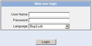
Figure 5-2 The login page of the Web-based network management system
5.3 Configuring the Login Banner
5.3.1 Configuration Procedure
If a login banner is configured with the header command, when a user logs in through Web, the banner page is displayed before the user login authentication page. The contents of the banner page are the login banner information configured with the header command. Then, by clicking <Continue> on the banner page, the user can enter the user login authentication page, and enter the main page of the Web-based network management system after passing the authentication. If no login banner is configured by the header command, a user logging in through Web directly enters the user login authentication page.
Table 5-2 Configure the login banner
|
Operation |
Command |
Description |
|
Enter system view |
system-view |
— |
|
Configure the banner to be displayed when a user logs in through Web |
header login text |
Required By default, no login banner is configured. |
5.3.2 Configuration Example
I. Network requirements
l A user logs in to the switch through Web.
l The banner page is desired when a user logs into the switch.
II. Network diagram
Figure 5-3 Network diagram for login banner configuration
III. Configuration Procedure
# Enter system view.
<Sysname> system-view
# Configure the banner "Welcome" to be displayed when a user logs into the switch through Web.
[Sysname] header login %Welcome%
Assume that a route is available between the user terminal (the PC) and the switch. After the above-mentioned configuration, if you enter the IP address of the switch in the address bar of the browser running on the user terminal and press <Enter>, the browser will display the banner page, as shown in Figure 5-4.

Figure 5-4 Banner page displayed when a user logs in to the switch through Web
Click <Continue> to enter user login authentication page. You will enter the main page of the Web-based network management system if the authentication succeeds.
5.4 Enabling/Disabling the WEB Server
Table 5-3 Enable/Disable the WEB Server
|
Operation |
Command |
Description |
|
Enter system view |
system-view |
— |
|
Enable the Web server |
ip http shutdown |
Required By default, the Web server is enabled. |
|
Disable the Web server |
undo ip http shutdown |
Required |
& Note:
To improve security and prevent attack to the unused Sockets, TCP 80 port (which is for HTTP service) is enabled/disabled after the corresponding configuration.
l Enabling the Web server (by using the undo ip http shutdown command) opens TCP 80 port.
l Disabling the Web server (by using the ip http shutdown command) closes TCP 80 port.
Chapter 6 Logging in through NMS
6.1 Introduction
You can also log into a switch through a network management station (NMS), and then configure and manage the switch through the agent module on the switch. Simple network management protocol (SNMP) is applied between the NMS and the agent. Refer to the SNMP-RMON part for related information.
To log into a switch through an NMS, you need to perform related configuration on both the NMS and the switch.
Table 6-1 Requirements for logging into a switch through an NMS
|
Item |
Requirement |
|
Switch |
The IP address of the VLAN interface of the switch is configured. The route between the NMS and the switch is reachable. (Refer to the IP Address Configuration – IP Performance Configuration and Routing Protocol parts for related information.) |
|
The basic SNMP functions are configured. (Refer to the SNMP-RMON part for related information.) |
|
|
NMS |
The NMS is properly configured. (Refer to the user manual of your NMS for related information.) |
6.2 Connection Establishment Using NMS

Figure 6-1 Network diagram for logging in through an NMS
Chapter 7 User Control
& Note:
Refer to the ACL part for information about ACL.
7.1 Introduction
A switch provides ways to control different types of login users, as listed in Table 7-1.
Table 7-1 Ways to control different types of login users
|
Login mode |
Control method |
Implementation |
Related section |
|
Telnet |
By source IP address |
Through basic ACL |
Section 7.2.2 “”Controlling Telnet Users by Source IP Addresses. |
|
By source and destination IP address |
Through advanced ACL |
Section 7.2.3 “Controlling Telnet Users by Source and Destination IP Addresses”. |
|
|
By source MAC address |
Through Layer 2 ACL |
Section 7.2.4 “Controlling Telnet Users by Source MAC Addresses” |
|
|
SNMP |
By source IP addresses |
Through basic ACL |
Section 7.3 “Controlling Network Management Users by Source IP Addresses”. |
|
WEB |
By source IP addresses |
Through basic ACL |
|
|
Disconnect Web users by force |
By executing commands in CLI |
7.2 Controlling Telnet Users
7.2.1 Prerequisites
The controlling policy against Telnet users is determined, including the source IP addresses, destination IP addresses and source MAC addresses to be controlled and the controlling actions (permitting or denying).
7.2.2 Controlling Telnet Users by Source IP Addresses
Table 7-2 Control Telnet users by source IP addresses
|
Operation |
Command |
Description |
|
Enter system view |
system-view |
— |
|
Create a basic ACL or enter basic ACL view |
acl number acl-number [ match-order { config | auto } ] |
As for the acl number command, the config keyword is specified by default. |
|
Define rules for the ACL |
rule [ rule-id ] { deny | permit } [ rule-string ] |
Required |
|
Quit to system view |
quit |
— |
|
Enter user interface view |
user-interface [ type ] first-number [ last-number ] |
— |
|
Apply the ACL to control Telnet users by source IP addresses |
acl acl-number { inbound | outbound } |
Required The inbound keyword specifies to filter the users trying to Telnet to the current switch. The outbound keyword specifies to filter users trying to Telnet to other switches from the current switch. |
7.2.3 Controlling Telnet Users by Source and Destination IP Addresses
Controlling Telnet users by source and destination IP addresses is achieved by applying advanced ACLs, which are numbered from 3000 to 3999.
Table 7-3 Control Telnet users by source and destination IP addresses
|
Operation |
Command |
Description |
|
Enter system view |
system-view |
— |
|
Create an advanced ACL or enter advanced ACL view |
acl number acl-number [ match-order { config | auto } ] |
As for the acl number command, the config keyword is specified by default. |
|
Define rules for the ACL |
rule [ rule-id ] { deny | permit } protocol [ rule-string ] |
Required You can define rules as needed to filter by specific source and destination IP addresses. |
|
Quit to system view |
quit |
— |
|
Enter user interface view |
user-interface [ type ] first-number [ last-number ] |
— |
|
Apply the ACL to control Telnet users by specified source and destination IP addresses |
acl acl-number { inbound | outbound } |
Required The inbound keyword specifies to filter the users trying to Telnet to the current switch. The outbound keyword specifies to filter users trying to Telnet to other switches from the current switch. |
7.2.4 Controlling Telnet Users by Source MAC Addresses
Table 7-4 Control Telnet users by source MAC addresses
|
Operation |
Command |
Description |
|
Enter system view |
system-view |
— |
|
Create or enter Layer 2 ACL view |
acl number acl-number |
— |
|
Define rules for the ACL |
rule [ rule-id ] { deny | permit } [ rule-string ] |
Required You can define rules as needed to filter by specific source MAC addresses. |
|
Quit to system view |
quit |
— |
|
Enter user interface view |
user-interface [ type ] first-number [ last-number ] |
— |
|
Apply the ACL to control Telnet users by specified source MAC addresses |
acl acl-number inbound |
Required By default, no ACL is applied for Telnet users. |
7.2.5 Configuration Example
I. Network requirements
Only the Telnet users sourced from the IP address of 10.110.100.52 are permitted to access the switch.
II. Network diagram

Figure 7-1 Network diagram for controlling Telnet users using ACLs
III. Configuration procedure
# Define a basic ACL.
<Sysname> system-view
[Sysname] acl number 2000
[Sysname-acl-basic-2000] rule 1 permit source 10.110.100.52 0
[Sysname-acl-basic-2000] quit
# Apply the ACL.
[Sysname] user-interface vty 0 4
[Sysname-ui-vty0-4] acl 2000 inbound
7.3 Controlling Network Management Users by Source IP Addresses
You can manage an S3100 Ethernet switch through network management software. Network management users can access switches through SNMP.
You need to perform the following two operations to control network management users by source IP addresses.
l Defining an ACL
l Applying the ACL to control users accessing the switch through SNMP
7.3.1 Prerequisites
The controlling policy against network management users is determined, including the source IP addresses to be controlled and the controlling actions (permitting or denying).
7.3.2 Controlling Network Management Users by Source IP Addresses
Controlling network management users by source IP addresses is achieved by applying basic ACLs, which are numbered from 2000 to 2999.
Follow these steps to control network management users by source IP addresses:
|
To do… |
Use the command… |
Remarks |
|
Enter system view |
system-view |
— |
|
Create a basic ACL or enter basic ACL view |
acl number acl-number [ match-order { auto | config } ] |
As for the acl number command, the config keyword is specified by default. |
|
Define rules for the ACL |
rule [ rule-id ] { deny | permit } [ rule-string ] |
Required |
|
Quit to system view |
quit |
— |
|
Apply the ACL while configuring the SNMP community name |
snmp-agent community { read | write } community-name [ acl acl-number | mib-view view-name ]* |
Required According to the SNMP version and configuration customs of NMS users, you can reference an ACL when configuring community name, group name or username. For the detailed configuration, refer to SNMP-RMON for more. |
|
Apply the ACL while configuring the SNMP group name |
snmp-agent group { v1 | v2c } group-name [ read-view read-view ] [ write-view write-view ] [ notify-view notify-view ] [ acl acl-number ] snmp-agent group v3 group-name [ authentication | privacy ] [ read-view read-view ] [ write-view write-view ] [ notify-view notify-view ] [ acl acl-number ] |
|
|
Apply the ACL while configuring the SNMP user name |
snmp-agent usm-user { v1 | v2c } user-name group-name [ acl acl-number ] snmp-agent usm-user v3 user-name group-name [ [ cipher ] authentication-mode { md5 | sha } auth-password [ privacy-mode { des56 | aes128 } priv-password ] ] [ acl acl-number ] |
7.3.3 Configuration Example
I. Network requirements
Only SNMP users sourced from the IP addresses of 10.110.100.52 are permitted to log into the switch.
II. Network diagram
Figure 7-2 Network diagram for controlling SNMP users using ACLs
III. Configuration procedure
# Define a basic ACL.
<Sysname> system-view
[Sysname] acl number 2000
[Sysname-acl-basic-2000] rule 1 permit source 10.110.100.52 0
[Sysname-acl-basic-2000] quit
# Apply the ACL to only permit SNMP users sourced from the IP addresses of 10.110.100.52 to access the switch.
[Sysname] snmp-agent community read aaa acl 2000
[Sysname] snmp-agent group v2c groupa acl 2000
[Sysname] snmp-agent usm-user v2c usera groupa acl 2000
7.4 Controlling Web Users by Source IP Address
You can manage an S3100 Ethernet switch remotely through Web. Web users can access a switch through HTTP connections.
You need to perform the following two operations to control Web users by source IP addresses.
l Defining an ACL
l Applying the ACL to control Web users
7.4.1 Prerequisites
The controlling policy against Web users is determined, including the source IP addresses to be controlled and the controlling actions (permitting or denying).
7.4.2 Controlling Web Users by Source IP Addresses
Controlling Web users by source IP addresses is achieved by applying basic ACLs, which are numbered from 2000 to 2999.
Table 7-5 Control Web users by source IP addresses
|
Operation |
Command |
Description |
|
Enter system view |
system-view |
— |
|
Create a basic ACL or enter basic ACL view |
acl number acl-number [ match-order { config | auto } ] |
As for the acl number command, the config keyword is specified by default. |
|
Define rules for the ACL |
rule [ rule-id ] { deny | permit } [ rule-string ] |
Required |
|
Quit to system view |
quit |
— |
|
Apply the ACL to control Web users |
ip http acl acl-number |
Optional By default, no ACL is applied for Web users. |
7.4.3 Disconnecting a Web User by Force
The administrator can disconnect a Web user by force using the related commands.
Table 7-6 Disconnect a Web user by force
|
Operation |
Command |
Description |
|
Disconnect a Web user by force |
free web-users { all | user-id user-id | user-name user-name } |
Required Execute this command in user view. |
7.4.4 Configuration Example
I. Network requirements
Only the Web users sourced from the IP address of 10.110.100.52 are permitted to access the switch.
II. Network diagram
Figure 7-3 Network diagram for controlling Web users using ACLs
III. Configuration procedure
# Define a basic ACL.
<Sysname> system-view
[Sysname] acl number 2030
[Sysname-acl-basic-2030] rule 1 permit source 10.110.100.52 0
[Sysname-acl-basic-2030] quit
# Apply ACL 2030 to only permit the Web users sourced from the IP address of 10.110.100.52 to access the switch.
[Sysname] ip http acl 2030