- Table of Contents
-
- H3C Low-End Ethernet Switches Configuration Examples(V1.04)
- 01-DHCP Configuration Examples
- 02-QACL Configuration Examples
- 03-802.1x Configuration Examples
- 04-SSH Configuration Examples
- 05-Routing Configuration Examples
- 06-Multicast Protocol Configuration Examples
- 07-VLAN Configuration Examples
- 08-Voice VLAN configuration examples
- 09-QinQ Configuration Examples
- 10-ARP Attack Prevention Configuration Examples
- Related Documents
-
| Title | Size | Download |
|---|---|---|
| 10-ARP Attack Prevention Configuration Examples | 1.15 MB |
Chapter 1 ARP Attack Prevention Overview
1.1 Introduction to ARP Attacks
1.2.5 Attack Prevention with the Support of a CAMS Server
1.3 Configuring ARP Attack Prevention
1.4 Device Models that Supports ARP Attack Prevention
Chapter 2 Configuration Examples
2.1 Configuration Example for ARP Attack Prevention in DHCP Snooping Mode
2.1.3 Configuration Considerations
2.1.4 Configuration Procedures
2.1.5 Configuration Guidelines
2.2 Configuration Example for ARP Attack Prevention in Authentication Mode
2.2.3 Configuration Considerations
2.2.4 Configuration Procedures
2.2.5 Configuration Guidelines
ARP Attack Prevention Configuration Examples
Keywords: ARP, DHCP snooping
Abstract: This document mainly describes how to implement ARP attack prevention in DHCP snooping mode or authentication mode on Ethernet switches, so as to prevent ARP attacks including gateway spoofing, spoofing gateway, spoofing terminal user, and ARP flood attacks. Meanwhile, this document describes in details the configuration procedures and precautions of the related networking devices.
Acronym: ARP (Address Resolution Protocol), MITM (Man-In-The-Middle).
Chapter 1 ARP Attack Prevention Overview
Recently, most campus networks suffer from ARP attacks possibly causing network access problems. According to the characteristics of ARP attacks, H3C brings forth a customized module for overall protection concept and provides two solutions as follows:
1) ARP attack prevention solution in DHCP snooping mode
This solution applies to network scenarios where IP addresses are assigned dynamically and DHCP snooping is enabled on the access switches. This solution, after applied to the entire network, can effectively prevent common ARP attacks including gateway spoofing, spoofing gateway, spoofing terminal user, ARP MITM, and ARP flood attacks. You do not need to install extra software on the terminals, and thus network configuration is simplified.
2) ARP attack prevention solution in authentication mode
1.1 Introduction to ARP Attacks
According to the ARP design, after receiving an ARP response, a host adds the IP-to-MAC mapping of the sender into its ARP mapping table even if the MAC address is not requested by itself. This can reduce the ARP traffic in the network, but it also makes ARP spoofing possible.
The following are some common ARP attacks on campus networks.
1) Gateway spoofing attack
In the following figure, an attacker sends an ARP packet with the gateway’s IP address and a fake MAC address to a client (Host A), which then updates the IP-to-MAC binding of the gateway. After that, traffic from the client to the gateway is sent to the fake MAC address, and the client is unable to access the external network.

Figure 1-1 Gateway spoofing attack
2) Spoofing gateway attack
In the following figure, an attacker sends an ARP packet with a client’s (Host A) IP address on the same network and a fake MAC address to the gateway which then updates the IP-to-MAC binding of the client. After that, traffic from the gateway to the client is sent to the fake MAC address, and the client cannot access the external network.

Figure 1-2 Spoofing gateway attack
3) Spoofing terminal user attack
In the following figure, an attacker sends an ARP packet with Host A’s IP address and a fake MAC address to Host C which then updates the IP-to-MAC binding of Host A. After that, traffic from Host C to Host A is sent to the fake MAC address, and thus unable to reach Host A.

Figure 1-3 Spoofing terminal user attack
4) MITM attack
ARP man-in-the-middle attack is also called ARP bidirectional attack. As shown in Figure 1-4, Host A communicates with Host C through a switch. To intercept the traffic between Host A and Host C, an attacker (Host B) forwards invalid ARP reply messages to Host A and Host C respectively, causing the two hosts to update the MAC address corresponding to the peer IP address in their ARP tables with the MAC address of Host B (MAC_B). Then, traffic between Host A and Host C will pass through Host B which acts like a “man-in-the-middle” and may intercept and modify the communication information. Such an attack is called a Man-In-The-Middle (MITM) attack.

5) ARP flood attack
An attacker sends numerous ARP packets to a port of a switch, which increases the CPU load, affecting the operation of other functions and possibly causing a device to crash.
1.2 ARP Attack Prevention
According to the characteristics of ARP attacks, H3C provides ARP attack prevention solutions of DHCP snooping mode and authentication mode. The former solution prevents common ARP attacks using DHCP snooping, IP static binding, ARP attack detection, and ARP packet rate limit. The latter solution prevents gateway spoofing attacks using IP-to-MAC binding entries provided by a CAMS server without needing to configure attack prevention on access switches.
Table 1-1 Common network attacks and prevention methods
|
Attack |
Prevention method |
|
Gateway spoofing, spoofing gateway, spoofing terminal users, and ARP MITM attacks from clients that obtain IP addresses dynamically. |
DHCP snooping, ARP attack detection |
|
Gateway spoofing, spoofing gateway, spoofing terminal users, and ARP MITM attacks from clients that have their IP addresses manually configured. |
IP static binding, ARP attack detection |
|
ARP flood attack |
ARP packet rate limit |
|
Gateway spoofing attacks from clients that have their IP addresses dynamically obtained or manually configured. |
ARP attack prevention solution in authentication mode (in which a CAMS server provides the gateway’s IP-to-MAC binding) |
1.2.1 DHCP Snooping Function
As a DHCP security feature, DHCP snooping can:
1) Record IP-to-MAC bindings of DHCP clients by listening to DHCP packets.
2) Ensure DHCP clients to obtain IP addresses from valid DHCP servers by setting DHCP snooping trusted ports.
l A trusted port forwards DHCP messages normally to guarantee that DHCP clients can obtain valid IP addresses from a DHCP server.
l An untrusted port discards the DHCP-ACK or DHCP-OFFER packets from any DHCP server to prevent DHCP clients from receiving invalid IP addresses.
& Note:
Currently, after DHCP snooping is enabled on an H3C low-end Ethernet switch, all the ports on the switch are DHCP snooping untrusted ports by default. You need to specify the ports connected to the valid DHCP servers as trusted to ensure that DHCP clients can obtain valid IP addresses. The trusted ports and the ports connected to DHCP clients must be in the same VLAN.
1.2.2 IP Static Binding
A DHCP snooping table only records IP-to-MAC bindings of clients that have obtained IP addresses through DHCP. If a client has a fixed IP address configured, its IP-to-MAC binding will not be recorded in the DHCP snooping table. The switch supports configuring IP static bindings, so that you can bind the client’s IP and MAC addresses and the port connected to the client. Thus, ARP packets sent from the client will not be filtered out through ARP attack detection.
1.2.3 ARP Attack Detection
H3C low-end switches can deliver received ARP packets (request or reply) to the CPU, and use DHCP snooping to verify the validity of the ARP packets as follows:
l If the source IP and MAC addresses, receiving port and its VLAN of an ARP packet match a DHCP snooping entry or an IP static binding entry, it is considered a valid ARP packet and is forwarded.
l If not, it is considered an invalid ARP packet and discarded.
& Note:
l A DHCP snooping table only records IP-to-MAC bindings of clients that have obtained IP addresses through DHCP. If a client with fixed IP address wants to access the network, you need to configure an IP static binding on the switch, that is, the binding of the IP and MAC addresses of the client, and the port connected to the client on the switch.
l You can configure an uplink port on a switch as trusted or untrusted to flexibly implement ARP attack detection for ARP requests and replies received on the port. The ARP packets received from an ARP trusted port are not detected, while the ARP packets received from untrusted ports are detected based on the DHCP snooping table and IP static bindings.
1.2.4 ARP Packet Rate Limit
H3C low-end Ethernet switches support ARP packet rate limit to shut down attacked ports temporarily to prevent damage to the CPU.
After ARP packet rate limit is enabled on a port, the switch collects statistics of ARP packets received on the port. If the number of ARP packets received per second exceeds the specified value, the port is considered attacked. Then, the port is shut down and does not receive any packet. The switch also supports port state auto-recovery function which can bring up the shut down port after the specified interval.
1.2.5 Attack Prevention with the Support of a CAMS Server
As shown in the following figure, a Comprehensive Access Management Server (CAMS), as the service management center connected with other networking devices (such as Ethernet switches) in a network, can implement authentication, authorization, accounting, and access management for users.

Figure 1-5 Network diagram for CAMS server
In this solution, you do not need to configure attack prevention on the access switches. The hosts only need to pass the 802.1x authentication to access the network. You have to specify the IP-to-MAC binding of the gateway on the CAMS server, which will provide the binding through access switches to the hosts to prevent gateway spoofing attacks.
1.3 Configuring ARP Attack Prevention
Table 1-2 Complete the following tasks to configure ARP attack prevention:
|
Task |
To do… |
Use the command… |
Remarks |
|
— |
Enter system view |
system-view |
— |
|
Configure DHCP snooping to record client’s IP-to-MAC bindings |
Enter Ethernet port view |
interface interface-type interface-number |
— |
|
Configure the port as a DHCP snooping trusted port |
dhcp-snooping trust |
Required By default, all the ports on a switch are DHCP snooping untrusted ports. |
|
|
Return to system view |
quit |
— |
|
|
Enable DHCP snooping |
dhcp-snooping |
Required Disabled by default. |
|
|
Configure an IP static binding on the specified port |
Enter Ethernet port view |
interface interface-type interface-number |
— |
|
Configure an IP static binding entry |
ip source static binding ip-address ip-address [ mac-address mac-address ] |
Optional Not configured by default. |
|
|
Return to system view |
quit |
— |
|
|
Configure ARP attack detection to prevent common ARP attacks |
Enter Ethernet port view |
interface interface-type interface-number |
— |
|
Configure the port as an ARP trusted port |
arp detection trust |
Optional By default, the port is an ARP untrusted port |
|
|
Return to system view |
quit |
— |
|
|
Enter VLAN view |
vlan vlan-id |
— |
|
|
Enable ARP attack detection |
arp detection enable |
Required By default, ARP attack detection is disabled on all the ports in the VLAN. |
|
|
Return to system view |
quit |
— |
|
|
Configure ARP packet rate limit |
Enter Ethernet port view |
interface interface-type interface-number |
— |
|
Enable ARP packet rate limit |
arp rate-limit enable |
Required Disabled by default. |
|
|
Configure the maximum ARP packet rate allowed on the port |
arp rate-limit rate |
Optional By default, the maximum ARP packet rate allowed on a port is 15 pps. |
|
|
Return to system view |
quit |
— |
|
|
Enable the port state auto-recovery function |
arp protective-down recover enable |
Optional Disabled by default. |
|
|
Configure the port state auto-recovery interval |
arp protective-down recover interval interval |
Optional By default, when the port state auto-recovery function is enabled, the port state auto-recovery interval is 300 seconds. |
& Note:
For detailed information about ARP attack prevention supported by a switch model, refer to its operation and command manuals.
1.4 Device Models that Supports ARP Attack Prevention
Table 1-3 Device models that supports ARP attack prevention
|
Feature Device model |
DHCP snooping |
ARP attack detection |
IP static binding |
ARP packet rate limit |
|
S5600 (Release 1602) |
l |
l |
l |
l |
|
S5100-EI (Release 2200) |
l |
l |
l |
l |
|
S5100-SI (Release 2200) |
l |
l |
l |
l |
|
l |
l |
l |
l |
|
|
S3600-SI (Release 1602) |
l |
l |
l |
l |
|
S3100-EI (Release 2104) |
l |
l |
l |
l |
|
S3100-52P (Release 1602) |
l |
l |
l |
l |
& Note:
For detailed information about ARP attack prevention supported by a switch model, refer to its operation manual.
Chapter 2 Configuration Examples
2.1 Configuration Example for ARP Attack Prevention in DHCP Snooping Mode
2.1.1 Network Requirements
In a campus network as shown in the following figure, hosts are connected to the gateway and DHCP server through access switches and obtain IP addresses dynamically. The administrator needs to configure ARP attack prevention on the access switches to prevent ARP attacks. The network requirements are as follows:
l Hosts in the campus network are located in Host area 1 (which belongs to VLAN 10) and Host area 2 (which belongs to VLAN 20) respectively, and they are connected to the Gateway and the DHCP server through Switch A and Switch B respectively.
l A TFTP server located in Host area 1 has an IP address of 192.168.0.10/24 and a MAC address of 000d-85c7-4e00.
l To prevent ARP attacks such as gateway spoofing and spoofing gateway attacks, enable ARP attack detection on VLAN 10 of Switch A and VLAN 20 of Switch B. Configure Ethernet 1/0/1 on Switch A and Switch B as ARP trusted ports.
l To prevent ARP flood attacks, enable ARP packet rate limit on the ports of Switch A and Switch B which directly connected to hosts. Meanwhile, enable port state auto-recovery on these ports and set the auto-recovery interval to 100 seconds.
2.1.2 Network Diagram

Figure 2-1 Network diagram for ARP attack prevention in DHCP snooping mode
2.1.3 Configuration Considerations
l Enable DHCP snooping on Switch A and Switch B, and configure their ports connected to the DHCP server as a DHCP snooping trusted port.
l Configure an IP static binding entry for the TFTP server on Switch A.
l Enable ARP attack detection on VLAN 10 of Switch A and VLAN 20 of Switch B respectively, and configure their uplink ports as ARP trusted ports.
l Configure ARP packet rate limit on the ports which directly connected to hosts of Switch A and Switch B, and enable the port state auto-recovery function globally on the two switches.
2.1.4 Configuration Procedures
I. Software version used
This example is configured and verified on S3100-EI series Ethernet switches Release2104.
II. Enable dynamic IP address allocation
Figure 2-2 Enable dynamic IP address allocation
III. Configure Switch A
# Create VLAN 10 and add Ethernet 1/0/1 through Ethernet 1/0/4 to VLAN 10.
<SwitchA> system-view
[SwitchA] vlan 10
[SwitchA-vlan10] port Ethernet 1/0/1 to Ethernet 1/0/4
[SwitchA-vlan10] quit
# Configure the uplink port on Switch A (Ethernet 1/0/1) as a DHCP snooping trusted port.
[SwitchA] interface ethernet1/0/1
[SwitchA-Ethernet1/0/1] dhcp-snooping trust
[SwitchA-Ethernet1/0/1] quit
# Enable DHCP Snooping.
[SwitchA] dhcp-snooping
# Configure an IP static binding entry for the TFTP server on Ethernet 1/0/4.
[SwitchA] interface Ethernet1/0/4
[SwitchA-Ethernet1/0/4] ip source static binding ip-address 192.168.0.10 mac-address 000d-85c7-4e00
[SwitchA-Ethernet1/0/4] quit
# Configure the uplink port on Switch A (Ethernet 1/0/1) as an ARP trusted port.
[SwitchA] interface ethernet1/0/1
[SwitchA-Ethernet1/0/1] arp detection trust
[SwitchA-Ethernet1/0/1] quit
# Enable ARP attack detection on all the ports in VLAN 10.
[SwitchA] vlan 10
[SwitchA-vlan10] arp detection enable
[SwitchA-vlan10] quit
# Enable ARP packet rate limit on Ethernet 1/0/2 and Ethernet 1/0/3 of Switch A.
[SwitchA] interface Ethernet1/0/2
[SwitchA-Ethernet1/0/2] arp rate-limit enable
[SwitchA-Ethernet1/0/2] arp rate-limit 20
[SwitchA-Ethernet1/0/2] quit
[SwitchA] interface Ethernet1/0/3
[SwitchA-Ethernet1/0/3] arp rate-limit enable
[SwitchA-Ethernet1/0/3] arp rate-limit 20
[SwitchA-Ethernet1/0/3] quit
# Enable port state auto-recovery and set the auto-recovery interval to 100 seconds.
[SwitchA] arp protective-down recover enable
[SwitchA] arp protective-down recover interval 100
# Configure a default route to Gateway.
[SwitchA] ip route-static 0.0.0.0 0 192.168.0.1
IV. Configure Switch B
# Create VLAN 20 and add Ethernet 1/0/1 through Ethernet 1/0/4 to VLAN 20.
<SwitchB> system-view
[SwitchB] vlan 20
[SwitchB-vlan20] port Ethernet 1/0/1 to Ethernet 1/0/4
[SwitchB-vlan20] quit
# Configure the uplink port on Switch B (Ethernet 1/0/1) as a DHCP snooping trusted port.
[SwitchB] interface ethernet1/0/1
[SwitchB-Ethernet1/0/1] dhcp-snooping trust
[SwitchB-Ethernet1/0/1] quit
# Enable DHCP snooping.
[SwitchB] dhcp-snooping
# Configure the uplink port on Switch B (Ethernet 1/0/1) as an ARP trusted port.
[SwitchB] interface ethernet1/0/1
[SwitchB-Ethernet1/0/1] arp detection trust
[SwitchB-Ethernet1/0/1] quit
# Enable ARP attack detection on all the ports in VLAN 20.
[SwitchB] vlan 20
[SwitchB-vlan20] arp detection enable
[SwitchB-vlan20] quit
# Enable ARP packet rate limit on Ethernet 1/0/2, Ethernet 1/0/3, and Ethernet 1/0/4 of Switch B.
[SwitchB] interface Ethernet1/0/2
[SwitchB-Ethernet1/0/2] arp rate-limit enable
[SwitchB-Ethernet1/0/2] arp rate-limit 20
[SwitchB-Ethernet1/0/2] quit
[SwitchB] interface Ethernet1/0/3
[SwitchB-Ethernet1/0/3] arp rate-limit enable
[SwitchB-Ethernet1/0/3] arp rate-limit 20
[SwitchB-Ethernet1/0/3] quit
[SwitchB] interface Ethernet1/0/4
[SwitchB-Ethernet1/0/4] arp rate-limit enable
[SwitchB-Ethernet1/0/4] arp rate-limit 20
[SwitchB-Ethernet1/0/4] quit
# Enable port state auto-recovery and set the auto-recovery interval to 100 seconds.
[SwitchB] arp protective-down recover enable
[SwitchB] arp protective-down recover interval 100
# Configure a default route to Gateway.
[SwitchB] ip route-static 0.0.0.0 0 192.168.1.1
V. Configure Gateway
<Gateway> system-view
# Create VLAN 10 and VLAN 20, and add corresponding ports into the VLANs.
[Gateway] vlan 10
[Gateway–vlan10] port Ethernet 1/0/1
[Gateway–vlan10] quit
[Gateway] vlan 20
[Gateway–vlan20] port Ethernet 1/0/2
[Gateway–vlan20] quit
# Configure the IP address of VLAN-interface 10 as 192.168.0.1/24.
[Gateway] interface vlan 10
[Gateway-Vlan-interface10] ip address 192.168.0.1 24
[Gateway-Vlan-interface10] quit
# Configure the IP address of VLAN-interface 20 as 192.168.1.1/24.
[Gateway] interface vlan 20
[Gateway-Vlan-interface20] ip address 192.168.1.1 24
[Gateway-Vlan-interface20] quit
VI. Configure the DHCP server
Because the configurations on the DHCP server vary with device models, the configurations are omitted. For details, refer to the related DHCP server configuration manual.
2.1.5 Configuration Guidelines
l Before configuring ARP attack detection, you need to enable DHCP snooping on the switch and configure DHCP snooping trusted ports; otherwise, no ARP packet can pass ARP attack detection.
l Currently, after DHCP snooping is enabled on an H3C low-end Ethernet switch, all the ports on the switch are DHCP snooping untrusted ports by default. You need to specify the ports connected to the valid DHCP servers as trusted to ensure that DHCP clients can obtain valid IP addresses. The trusted ports and the ports connected to DHCP clients must be in the same VLAN.
l A DHCP snooping table only records IP-to-MAC bindings of clients that have obtained IP addresses through DHCP. If a client with fixed IP address wants to access the network, you need to configure an IP static binding on the switch, that is, the binding of the IP and MAC addresses of the client, and the port connected to the client on the switch.
l Currently, when you configure an IP static binding entry on a port of an H3C series Ethernet switch, the VLAN ID of the entry is the default VLAN ID of the port. Therefore, if an ARP packet has a VLAN tag different from the default VLAN ID of the receiving port, it does not match the IP static binding entry and thus fails to pass ARP attack detection.
l An IP static binding entry configured on an H3C series Ethernet switch has a higher priority than a DHCP snooping entry: If the IP address in an IP static binding entry is the same as that in a DHCP snooping entry, the IP static binding entry overwrites the DHCP snooping entry; if the IP static binding entry is configured before DHCP snooping is enabled, no DHCP client cannot obtain the IP address specified in the IP static binding entry through the switch.
l You can configure an uplink port on a switch as trusted or untrusted to flexibly implement ARP attack detection for ARP requests and replies received on the port. The ARP packets received from an ARP trusted port are not detected, while the ARP packets received from other ports are detected based on the DHCP snooping table and IP static bindings.
2.2 Configuration Example for ARP Attack Prevention in Authentication Mode
2.2.1 Network Requirements
In a campus network as shown in the following figure, the hosts are connected to the gateway and servers through access switches. The administrator needs to configure the gateway’s IP-to-MAC binding on the CAMS server for the clients to prevent gateway spoofing attacks. The network requirements are as follows:
l The hosts can be configured with IP addresses statically or obtain IP addresses through DHCP. You need to install 802.1x client software on the hosts so that the hosts need to pass 802.1x authentication before accessing the network.
l The H3C CAMS server serves as an authentication, authorization, and accounting server that provides the gateway’s IP-to-MAC binding to clients to prevent gateway spoofing attacks.
l You need to configure 802.1x and AAA on the access switches.
2.2.2 Network Diagram

Figure 2-3 Network diagram for ARP attack prevention in authentication mode
2.2.3 Configuration Considerations
l Install 802.1x client software on the hosts so that the hosts need to pass 802.1x authentications before accessing the network.
l Configure 802.1x and AAA on Switch A and Switch B.
l Configure the gateway’s IP-to-MAC binding on the CAMS server which will provide the binding to clients for preventing gateway spoofing attacks.
2.2.4 Configuration Procedures
I. Configure Switch A
# Create VLAN 10, and add Ethernet 1/0/1 through Ethernet 1/0/3 into VLAN 10.
<SwitchA> system-view
[SwitchA] vlan 10
[SwitchA-vlan10] port Ethernet 1/0/1 to Ethernet 1/0/3
[SwitchA-vlan10] quit
# Configure RADIUS scheme cams and specify a primary authentication server.
[SwitchA] radius scheme cams
[SwitchA-radius-cams] primary authentication 10.10.1.1
[SwitchA-radius-cams] accounting optional
# Set the RADIUS authentication key to expert.
[SwitchA-radius-cams] key authentication expert
# Specify usernames sent to the RADIUS server to exclude the domain name.
[SwitchA-radius-cams] user-name-format without-domain
# Specify the service type as extended.
[SwitchA-radius-cams] server-type extended
[SwitchA-radius-cams] quit
# Create ISP domain host and reference RADIUS scheme cams.
[SwitchA] domain host
[SwitchA-isp-host] radius-scheme cams
[SwitchA-isp-host] quit
# Set ISP domain host as the default ISP domain.
[SwitchA] domain default enable host
# Enable 802.1x globally.
[SwitchA] dot1x
# Enable 802.1x on Ethernet 1/0/2.
[SwitchA] interface Ethernet1/0/2
[SwitchA-Ethernet1/0/2] dot1x
[SwitchA-Ethernet1/0/2] quit
# Enable 802.1x on Ethernet 1/0/3.
[SwitchA] interface Ethernet1/0/3
[SwitchA-Ethernet1/0/3] dot1x
[SwitchA-Ethernet1/0/3] quit
# Configure a default route to Gateway.
[SwitchA] ip route-static 0.0.0.0 0 192.168.0.1
II. Configure Switch B
# Create VLAN 20, and add Ethernet 1/0/1 through Ethernet 1/0/4 into VLAN 20.
<SwitchB> system-view
[SwitchB] vlan 20
[SwitchB-vlan20] port Ethernet 1/0/1 to Ethernet 1/0/4
[SwitchB-vlan20] quit
# Configure RADIUS scheme cams and specify a primary authentication server.
[SwitchB] radius scheme cams
[SwitchB-radius-cams] primary authentication 10.10.1.1
[SwitchB-radius-cams] accounting optional
# Set the RADIUS authentication key to expert.
[SwitchB-radius-cams] key authentication expert
# Specify usernames sent to the RADIUS server to exclude the domain name.
[SwitchB-radius-cams] user-name-format without-domain
# Specify the service type as extended.
[SwitchB-radius-cams] server-type extended
[SwitchB-radius-cams] quit
# Create ISP domain host and reference RADIUS scheme cams.
[SwitchB] domain host
[SwitchB-isp-host] radius-scheme cams
[SwitchB-isp-host] quit
# Set ISP domain host as the default ISP domain.
[SwitchB] domain default enable host
# Enable 802.1x globally.
[SwitchB] dot1x
# Enable 802.1x on Ethernet 1/0/2, Ethernet 1/0/3, and Ethernet 1/0/4.
[SwitchB] interface Ethernet1/0/2
[SwitchB-Ethernet1/0/2] dot1x
[SwitchB-Ethernet1/0/2] quit
[SwitchB] interface Ethernet1/0/3
[SwitchB-Ethernet1/0/3] dot1x
[SwitchB-Ethernet1/0/3] quit
[SwitchB] interface Ethernet1/0/4
[SwitchB-Ethernet1/0/4] dot1x
[SwitchB-Ethernet1/0/4] quit
# Configure a default route to Gateway.
[SwitchB] ip route-static 0.0.0.0 0 192.168.1.1
III. Configure Gateway
<Gateway> system-view
# Create VLAN 10 and VLAN 20, and add corresponding ports into the VLANs.
[Gateway] vlan 10
[Gateway–vlan10] port Ethernet 1/0/1
[Gateway–vlan10] quit
[Gateway] vlan 20
[Gateway–vlan20] port Ethernet 1/0/2
[Gateway–vlan20] quit
# Configure the IP address of VLAN-interface 10 as 192.168.0.1/24.
[Gateway] interface vlan 10
[Gateway-Vlan-interface10] ip address 192.168.0.1 24
[Gateway-Vlan-interface10] quit
# Configure the IP address of VLAN-interface 20 as 192.168.1.1/24.
[Gateway] interface vlan 20
[Gateway-Vlan-interface20] ip address 192.168.1.1 24
[Gateway-Vlan-interface20] quit
IV. Configure the RADIUS server (CAMS 2.10-R0210)
1) Enter the correct username and password on the login page to log in to the CAMS server.
2) Create a service type.
Log in the CAMS server configuration page, and then select Service Management > Service Config from the navigation tree to enter the Service Config page, as shown in the following figure.
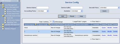
Figure 2-4 Service Config page
Click Add to enter the Add Service page.
l Enter Host for Service Name in the Basic Info field.
l Select CAMS-compliant client only in the Client Configuration field and select Unlimited for Ways to Obtain IP Addresses.
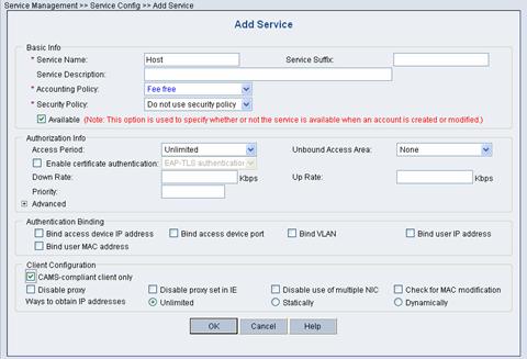
Figure 2-5 Add Service page
Click OK.
3) Add a user account (Host)
Log in the CAMS server configuration platform, and then select User Management > Account User from the navigation tree to enter the Account Management page, as shown in the following figure.
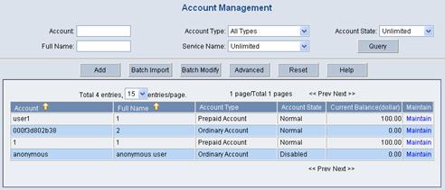
Figure 2-6 Account Management page
Click Add to enter the Add Account page.
l Enter Host for Account, Host for Password, and Host for Full Name.
l Select service Host in the Service Information field.
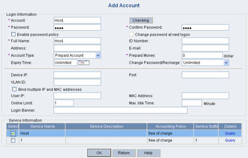
Figure 2-7 Add Account page
Click OK.
4) Configure an access device
Log in the CAMS server configuration platform, and then select System Management > System Configuration from the navigation tree to enter the System Configuration page, as shown in the following figure.

Figure 2-8 System Configuration page
Select Access Device and click Modify. Click Add to enter the Add Access Device page.
Enter the required information such as IP address and shared key for the access device, as shown in the following figure.
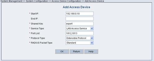
Figure 2-9 Add Access Device page
Click OK and the following dialog box appears.
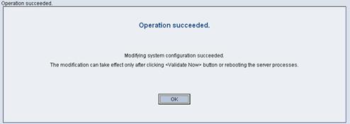
Figure 2-10 Operation succeeded dialog box
Return to the System Configuration page and then click Validate Now.

Figure 2-11 Validate the setting
5) Configure the gateway
Log in the CAMS server configuration platform, and then select System Management > System Configuration from the navigation tree to enter the System Configuration page, as shown in the following figure.
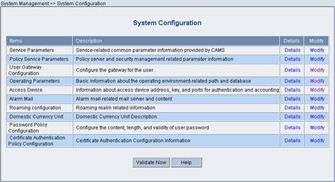
Figure 2-12 System Configuration page
Select User Gateway Configuration and then click Modify.
Click Add to enter the Add Gateway Configuration page. (Take VLAN-interface 10 on Gateway in Figure 2-3 as an example.)
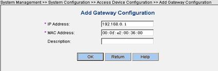
Figure 2-13 Add Gateway Configuration page
Click OK to return to the System Configuration page, and then click Validate Now.
V. Configure the client
You need to install H3C iNode client on the PC.
See the following steps for configuration details:
1) Launch the client

Figure 2-14 Wizard page
2) Select 802.1x protocol
Click Next.
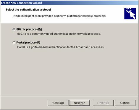
Figure 2-15 Select 802.1x
Select Common connection, and then click Next.
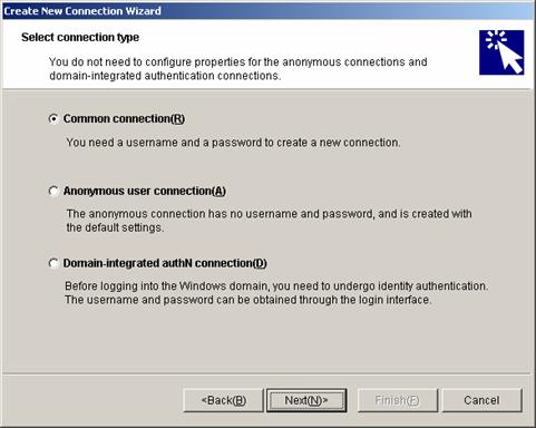
Figure 2-16 Select Common connection
3) Specify the username and password
Click Next.
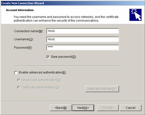
Figure 2-17 Specify the username and password
4) Set the connection property
Click Next.
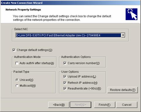
Figure 2-18 Set the connection property
5) Complete the creation of the connection
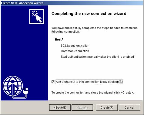
Figure 2-19 Complete connection creation
6) Start the connection
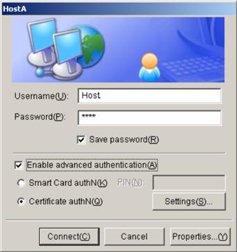
Figure 2-20 Start the connection
2.2.5 Configuration Guidelines
l If there are many user network segments, information about gateways configured on the CAMS server may not be completely received by an access switch, because the total number of configured gateways exceeds the upper limit supported by the switch. Refer to your product specification for the maximum number of gateways supported on the CAMS server and that on the access switch.
l You need to execute the server-type extended command when configuring the RADIUS scheme on an access switch.