- Table of Contents
-
- H3C Low-End Ethernet Switches Configuration Examples(V1.04)
- 01-DHCP Configuration Examples
- 02-QACL Configuration Examples
- 03-802.1x Configuration Examples
- 04-SSH Configuration Examples
- 05-Routing Configuration Examples
- 06-Multicast Protocol Configuration Examples
- 07-VLAN Configuration Examples
- 08-Voice VLAN configuration examples
- 09-QinQ Configuration Examples
- 10-ARP Attack Prevention Configuration Examples
- Related Documents
-
| Title | Size | Download |
|---|---|---|
| 03-802.1x Configuration Examples | 638.75 KB |
Table of Contents
1.2.2 Configuration in Port View
Chapter 2 802.1X Configuration Commands
Chapter 3 Enterprise Network Access Authentication Configuration Example
3.1 Network Application Analysis
3.3.2 Configuring the RADIUS Server
3.3.3 Configuring the Supplicant System
Keywords: 802.1x and AAA
Abstract: This article introduces the application of 802.1x on Ethernet switches in real network environments, and then presents detailed configurations of the 802.1x client, LAN Switch and AAA server respectively.
Acronyms: AAA (Authentication, Authorization and Accounting)
Chapter 1 802.1X Overview
& Note:
The use of this document is restricted to H3C S3600, H3C S5600, H3C S3100, H3C S5100 and H3C S3100-52P Series Ethernet switches.
1.1 Introduction to 802.1X
The LAN defined in IEEE 802 protocols does not provide access authentication. In general, users can access network devices or resources in a LAN as long as they access the LAN. When it comes to application circumstances like telecom network access, building, LAN and mobile office, however, administrators need to control and configure the access of user devices. Therefore, port- or user-based access control comes into being.
802.1x is a port-based network access control protocol. It is widely accepted by vendors, service providers and end users for its low cost, superior service continuity and scalability, and high security and flexibility.
1.2 Features Configuration
1.2.1 Global Configuration
l Enable 802.1x globally
l Set time parameters
l Set the maximum number of authentication request attempts
l Enable the quiet timer
l Enable re-authentication upon reboot
1.2.2 Configuration in Port View
l Enable dot1x on the port
l Enable Guest VLAN
l Set the maximum number of users supported on the port
l Set a port access control method (port-based or MAC-based)
l Set a port access control mode (force-authorized, force-unauthorized or auto)
l Enable client version checking
l Enable proxy detection
1.2.3 Precautions
l The configuration of dot1x takes effect only after the dot1x feature is enabled globally.
l You can configure dot1x parameters associated with Ethernet ports or devices before enabling dot1x. However, the configured dot1x parameters only take effect after dot1x is enabled.
l The configured dot1x parameters are reserved after dot1x is disabled and will take effect if dot1x is re-enabled.
Chapter 2 802.1X Configuration Commands
To implement 802.1x, you need to configure the supplicant system (client), authenticator system (switch) and authentication/authorization server correctly.
l Supplicant system: Ensures that the PC uses a right client.
l Authenticator system: Configuring 802.1x and AAA on the authenticator system is required.
l Authentication/authorization server: Configuring the authentication/authorization server correctly is required.
The following table shows 802.1x configuration commands necessary for configuring the switch (authenticator system). For configuration information on other devices, refer to related manuals.
Table 2-1 802.1x configuration commands
|
To do… |
Use the command… |
Remarks |
|
Enable 802.1x globally |
dot1x |
Required Disabled by default |
|
Enable 802.1x on one or more ports |
In system view dot1x [ interface interface-list ] |
Required Disabled on a port by default 802.1x must be enabled both globally in system view and on the intended port in system view or port view. Otherwise, it does not function. |
|
In port view dot1x |
||
|
Set a port access control method for the specified or all ports |
dot1x port-method { macbased | portbased } [ interface interface-list ] |
Optional macbased by default Port-based access control is required for Guest VLAN. |
|
Enable a Guest VLAN on the specified or all ports |
dot1x guest-vlan vlan-id [ interface interface-list ] |
Required Not enabled by default. The vlan-id of the Guest VLAN must be created beforehand. |
Chapter 3 Enterprise Network Access Authentication Configuration Example
& Note:
The configuration or information displayed may vary with devices. The following takes the H3C S3600 series switch (using software Release 1510) as an example.
3.1 Network Application Analysis
An administrator of an enterprise network needs to authenticate users accessing the network on a per-port basis on the switch to control access to network resources. Table 3-1 shows the details of network application analysis.
Table 3-1 Network application analysis
|
Network requirements |
Solution |
|
Access of users is controlled by authentication. |
Enable 802.1x |
|
Users can only access VLAN 10 before the authentication succeeds. |
Enable Guest VLAN |
|
Users can access VLAN 100 after the authentication succeeds. |
Enable dynamic VLAN assignment |
|
Users select the monthly payment service of 50 dollars and use 2M bandwidth to access the network. |
Configure an accounting policy and bandwidth restraint policy on the RADIUS server |
|
IP address and MAC address are bound after a user logs in. |
Set MAC-to-IP binding |
|
Tear down the connection by force if it is idle for 20 minutes. |
Enable idle cut |
|
Users can be re-authenticated successfully after the switch reboots abnormally. |
3.2 Network Diagram

Figure 3-1 Network diagram for enterprise network application
3.3 Configuration Procedure
3.3.1 Configuring the Switch
# Create a RADIUS scheme named cams, and specify the primary and secondary authentication/accounting servers.
<H3C> system-view
[H3C] radius scheme cams
[H3C-radius-cams] primary authentication 192.168.1.19
[H3C-radius-cams] primary accounting 192.168.1.19
[H3C-radius-cams] secondary authentication 192.168.1.20
[H3C-radius-cams] secondary accounting 192.168.1.20
# Set the password to expert for the switch to exchange messages with the RADIUS authentication and accounting servers.
[H3C-radius-cams] key authentication expert
[H3C-radius-cams] key accounting expert
# Set the username format to fully qualified user name with domain name.
[H3C-radius-cams] user-name-format with-domain
# Set the server type to extended.
[H3C-radius-cams] server-type extended
# Enable re-authentication upon reboot.
[H3C-radius-cams] accounting-on enable
# Create an ISP domain named abc and adopt the RADIUS scheme cams for authentication.
[H3C] domain abc
[H3C-isp-abc] radius-scheme cams
[H3C-isp-abc] quit
# Set the ISP domain abc as the default ISP domain.
[H3C] domain default enable abc
# Enable dynamic VLAN assignment.
[H3C-isp-abc] vlan-assignment-mode integer
# Enable Guest VLAN 10 on the specified port.
[H3C] vlan 10
[H3C-Ethernet1/0/3] dot1x port-method portbased
[H3C-Ehternet1/0/3] dot1x guest-vlan 10
# Enable 802.1x.
[H3C] dot1x
# Enable dot1x in port view.
[H3C-Ethernet1/0/3] dot1x
# Use the display command to view the configuration associated with 802.1x and AAA parameters.
[H3C] display dot1x interface ethernet1/0/3
Global 802.1x protocol is enabled
CHAP authentication is enabled
DHCP-launch is disabled
Proxy trap checker is disabled
Proxy logoff checker is disabled
Configuration: Transmit Period 30 s, Handshake Period 15 s
ReAuth Period 3600 s, ReAuth MaxTimes 2
Quiet Period 60 s, Quiet Period Timer is disabled
Supp Timeout 30 s, Server Timeout 100 s
Interval between version requests is 30s
Maximal request times for version information is 3
The maximal retransmitting times 2
Total maximum 802.1x user resource number is 1024
Total current used 802.1x resource number is 0
Ethernet1/0/3 is link-up
802.1x protocol is enabled
Proxy trap checker is disabled
Proxy logoff checker is disabled
Version-Check is disabled
The port is an authenticator
Authentication Mode is Auto
Port Control Type is Port-based
ReAuthenticate is disabled
Max number of on-line users is 256
Authentication Success: 0, Failed: 0
EAPOL Packets: Tx 0, Rx 0
Sent EAP Request/Identity Packets : 0
EAP Request/Challenge Packets: 0
Received EAPOL Start Packets : 0
EAPOL LogOff Packets: 0
EAP Response/Identity Packets : 0
EAP Response/Challenge Packets: 0
Error Packets: 0
Controlled User(s) amount to 0
[H3C] display radius scheme cams
SchemeName =cams Index=1 Type=extended
Primary Auth IP =192.168.1.19 Port=1812
Primary Acct IP =192.168.1.19 Port=1813
Second Auth IP =192.168.1.20 Port=1812
Second Acct IP =192.168.1.20 Port=1813
Auth Server Encryption Key= expert
Acct Server Encryption Key= expert
Accounting method = required
Accounting-On packet enable, send times = 15 , interval = 3s
TimeOutValue(in second)=3 RetryTimes=3 RealtimeACCT(in minute)=12
Permitted send realtime PKT failed counts =5
Retry sending times of noresponse acct-stop-PKT =500
Quiet-interval(min) =5
Username format =with-domain
Data flow unit =Byte
Packet unit =1
unit 1 :
Primary Auth State=active, Second Auth State=active
Primary Acc State=active, Second Acc State=active
[H3C] display domain abc
The contents of Domain abc:
State = Active
RADIUS Scheme = cams
Access-limit = Disable
Vlan-assignment-mode = Integer
Domain User Template:
Idle-cut = Disable
Self-service = Disable
Messenger Time = Disable
3.3.2 Configuring the RADIUS Server
The configuration of CAMS authentication, authorization and accounting server consists of four parts:
l Creating an accounting policy
l Configuring the access device
The following parts take CAMS server V1.20 (standard version) as an example to introduce CAMS configuration.
I. Logging in the CAMS configuration console
1) Enter the correct user name and password on the login page to log in to the CAMS configuration console.

Figure 3-2 Login page of CAMS configuration console
2) After login, the following page appears:
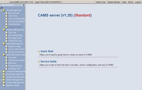
Figure 3-3 CAMS configuration console
II. Creating an accounting policy
1) Enter the Accounting Policy Management page.
Log in the CAMS configuration console. On the navigation tree, select [Charges Management/Accounting Policy] to enter the [Accounting Policy Management] page, as shown in Figure 3-4.
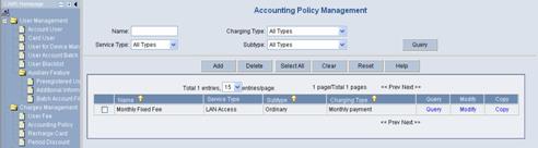
Figure 3-4 Accounting Policy Management
The list shows the created accounting policies. You can query, modify or maintain these policies.
2) Create an accounting policy.
Click <Add> to enter the [Accounting Policy Basic Information] page and create a monthly payment accounting policy, as shown in Figure 3-5.
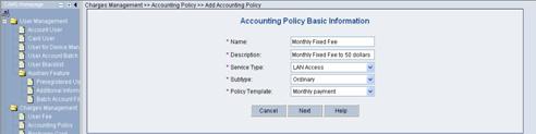
Figure 3-5 Accounting Policy Basic Information
3) Click <Next> to enter the [Accounting Attribute Settings] page, and set Accounting Type to By duration, Monthly Cycle to Monthly and Monthly Fixed Fee to 50 dollars, as shown in Figure 3-6.
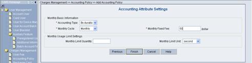
Figure 3-6 Accounting Attribute Settings
Click <OK>. A monthly payment accounting policy is created.
III. Adding a service
1) Enter the Service Config page.
Log in the CAMS configuration console. On the navigation tree, select [Service Management/Service Config] to enter the [Service Config] page, as shown in Figure 3-7.
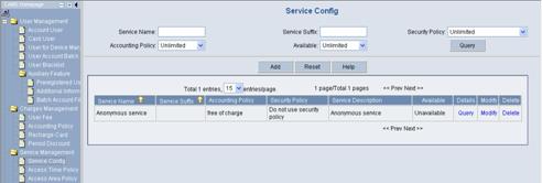
The list shows the created service types. You can query, modify or delete these service types.
2) Add a service.
Click <Add> to enter the [Add Service] page and configure as follows:
l Service Name: abc
l Service Suffix Name: abc
l Accounting Policy: Monthly Fixed Payment
l Upstream Rate Limitation: 2M (2048 Kbps)
l Downstream Rate Limitation: 2M (2048 Kbps)
l VLAN Assignment: VLAN 100
l Authentication Binding: Bind user IP address and bind user MAC address
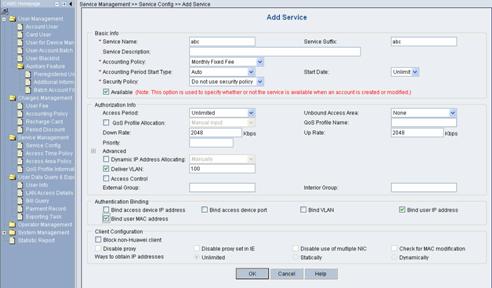
Figure 3-8 Add Service
Click <OK>. A service type is added.
IV. Adding an account user
1) Enter the Account Management page.
Log in the CAMS configuration console. On the navigation tree, select [User Management/Account User] to enter the [Account Management] page, as shown in Figure 3-9.
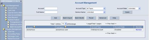
Figure 3-9 Account Management
The list shows the created account users. You can maintain these account users.
2) Add an account user.
Click <Add> to enter the [Add Account] page and configure as follows:
l Account: info
l Password: info
l Full Name: Bruce
l Prepaid Money: 100 dollars
l Bind multiple IP address and MAC address: enable
l Online Limit: 1
l Max. Idle Time: 20 minutes
l Service Information: abc
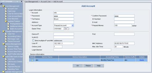
Figure 3-10 Add Account
Click <OK>. An account user is added.
V. Configuring the access device
1) Enter the System Configuration page.
Log in the CAMS configuration console. On the navigation tree, select [System Management/System Configuration] to enter the [System Configuration] page, as shown in Figure 3-11.
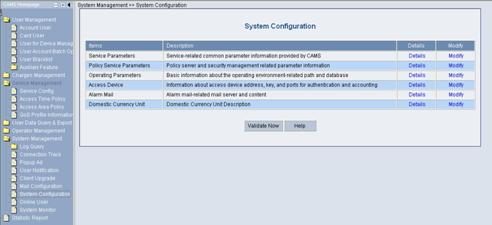
Figure 3-11 System Configuration
2) Click the Modify link for the Access Device item to enter the [Access Device Configuration] page to modify access device configuration like IP address, shared key, and authentication and accounting ports.
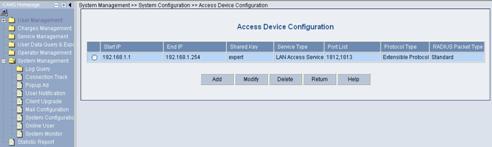
Figure 3-12 Access Device Configuration
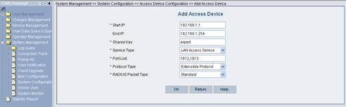
VI. Adding configuration item
1) Click <Add> to enter the [Add Access Device] page and add configuration items, as shown in Figure 3-13.
2) Click <OK>. The prompt page appears as shown in Figure 3-14.
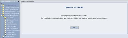
Figure 3-14 Page prompting that system configuration is modified successfully
3) Return to the [System Configuration] page and click <Validate Now> to make the configuration take effect immediately.
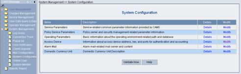
Figure 3-15 Validate Now on System Management page
3.3.3 Configuring the Supplicant System
You need to install an 802.1x client on the PC, which may be H3C’s 802.1x client, the client shipped with Windows XP or other client from the third party. The following takes H3C’s 802.1X as an example to introduce how to configure the supplicant system.
I. Starting up H3C authentication client
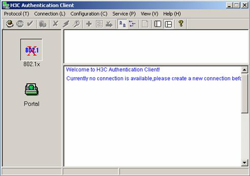
Figure 3-16 H3C authentication client
II. Creating a connection
Right click the 802.1x Authentication icon and select [Create an 802.1x connection], as shown in Figure 3-17.
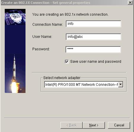
Figure 3-17 Create an 802.1x connection
III. Configuring connection attributes
Click <Next> to enter the [Set special properties] page:
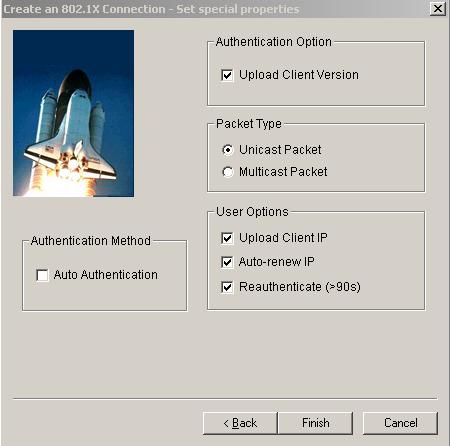
Figure 3-18 Set special properties
Keep default settings and click <OK>. The prompt page appears as shown in Figure 3-19.
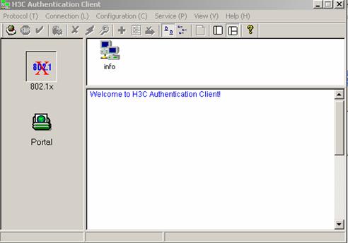
Figure 3-19 Page prompting that a connection is created successfully
IV. Initiating the connection
Double click the info connection:
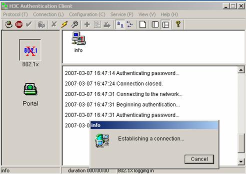
Figure 3-20 Connecting
The connection succeeds:
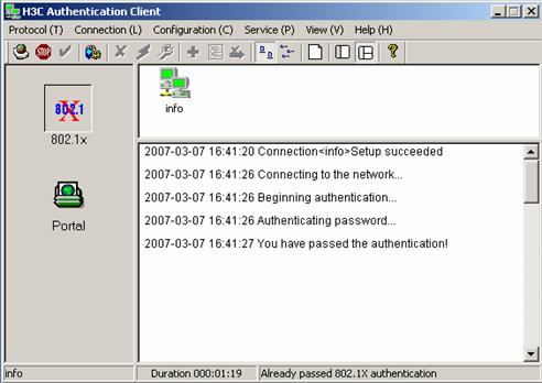
Figure 3-21 Page prompting that the Authentication succeeds
3.3.4 Verifying Configuration
To verify that the configuration of Guest VLAN is taking effect, check that users can access VLAN 10 before 802.1x authentication or the 802.1x authentication fails.
To verify that the dynamically assigned VLAN is taking effect, check that users can access VLAN 100 after 802.1x authentication succeeds. At the same time, 802.1x authentication cooperates with CAMS to complete accounting and real time monitoring.
To verify that the configuration of IP-to-MAC binding is taking effect, check that users can be re-authenticated and access the Internet when the device reboots abnormally. If the configured IP-to-MAC binding is different from that on the CAMS, the user cannot access the Internet.
3.3.5 Troubleshooting
I. Symptom: 802.1x authentication failed
Solution:
l Use the display dot1x command to verify 802.1x is enabled globally and on the specified ports.
l Verify the username and password are set correctly.
l Verify the connection works well.
l Use the debugging dot1x packet command to verify the switch receives and sends EAP and EAPoL packets normally.
II. Symptom: Users can access network resources without 802.1x authentication
l Use the display dot1x command to verify 802.1x is enabled globally and on the specified ports.
l Use the display interface command to verify the statistics of incoming packets are available for the specified port. 802.1x authentication applies only to incoming packets, not outgoing packets.