- Table of Contents
-
- H3C Low-End Ethernet Switches Configuration Examples(V1.04)
- 01-DHCP Configuration Examples
- 02-QACL Configuration Examples
- 03-802.1x Configuration Examples
- 04-SSH Configuration Examples
- 05-Routing Configuration Examples
- 06-Multicast Protocol Configuration Examples
- 07-VLAN Configuration Examples
- 08-Voice VLAN configuration examples
- 09-QinQ Configuration Examples
- 10-ARP Attack Prevention Configuration Examples
- Related Documents
-
| Title | Size | Download |
|---|---|---|
| 08-Voice VLAN configuration examples | 212.1 KB |
Table of Contents
1.2.1 Configuring a Voice VLAN in automatic mode
1.2.2 Configuring a Voice VLAN in manual mode
Chapter 2 Configuration Examples
2.1 Voice VLAN Configuration Examples
Voice VLAN Configuration Examples
Keywords: VLAN, 802.1q, voice VLAN
Abstract: This document introduces how voice VLAN of the H3C series Ethernet switches is applied and configured in a network.
Acronyms: VLAN (Virtual local area network)
Chapter 1 Voice VLAN Overview
1.1 Applicable Switches
This configuration example is applicable to the following models support voice VLAN:
l S3600
l S5600
l S5100-EI
l S3100-EI
1.2 Configuring Voice VLAN
& Note:
l For how to configure VLAN, port type and other related functions that voice VLAN configuration involves, refer to the operation manual that accompanies your product.
l The configuration procedure differs by device. In this configuration example, the S3600 series are taken as an example. For how to configure voice VLAN on other models, refer to their accompanied operation manuals.
l The configuration example in this guide provides only basic configuration procedures. For detailed information about the involved functions, refer to the corresponding operation manual and command manual.
1.2.1 Configuring a Voice VLAN in automatic mode
Follow these steps to configure a voice VLAN in automatic mode:
|
To do... |
Use the command... |
Remarks |
|
Enter system view |
system-view |
— |
|
Add a recognizable voice device vendor OUI to the OUI address list |
voice vlan mac-address oui mask oui-mask [ description text ] |
Optional By default, the switch identifies voice traffic according to the default OUI address list. |
|
Enable the voice VLAN security mode |
voice vlan security enable |
Optional Enabled by default. |
|
Set the voice VLAN aging time |
voice vlan aging minutes |
Optional 1440 minutes by default. |
|
Enable voice VLAN globally |
voice vlan vlan-id enable |
Required |
|
Enter Ethernet port view |
interface interface-type interface-number |
— |
|
Enable voice VLAN on the port |
voice vlan enable |
Required Disabled by default. |
|
Enable voice VLAN legacy on the port to allow for automatic voice VLAN assignment for voice traffic from third-party vendors’ voice devices |
voice vlan legacy |
Optional Disabled by default. |
|
Configure the voice VLAN to operate in automatic mode on the port |
voice vlan mode auto |
Optional Automatic mode applies by default. |
1.2.2 Configuring a Voice VLAN in manual mode
Follow these steps to configure a voice VLAN in manual mode:
|
To do... |
Use the command... |
Remarks |
||
|
Enter system view |
system-view |
— |
||
|
Add a recognizable voice device vendor OUI to the OUI address list |
voice vlan mac-address oui mask oui-mask [ description text ] |
Optional By default, the switch identifies voice traffic according to the default OUI address list. |
||
|
Enable the voice VLAN security mode |
voice vlan security enable |
Optional Enabled by default. |
||
|
Set the voice VLAN aging time |
voice vlan aging minutes |
Optional 1440 minutes by default. |
||
|
Enable voice VLAN globally |
voice vlan vlan-id enable |
Required |
||
|
Enter Ethernet port view |
interface interface-type interface-number |
— |
||
|
Enable voice VLAN on the port |
voice vlan enable |
Required Disabled by default. |
||
|
Enable voice VLAN legacy on the port to allow for automatic voice VLAN assignment for voice traffic from third-party vendors’ voice devices |
voice vlan legacy |
Optional Disabled by default. |
||
|
Configure the voice VLAN to operate in manual mode on the port |
undo voice vlan mode auto |
Required Automatic mode applies by default. |
||
|
Return to system view |
quit |
— |
||
|
Assign the port to the voice VLAN |
Access port |
Enter VLAN view |
vlan vlan-id |
Required |
|
Assign the specified port(s) to the VLAN |
port interface-list |
|||
|
Trunk port or hybrid port |
Enter port view |
interface interface-type interface-number |
||
|
Assign the port to the specified VLAN |
port trunk permit vlan vlan-id port hybrid vlan vlan-id { tagged | untagged } |
|||
|
Configure the voice VLAN as the default VLAN of the port |
port trunk pvid vlan vlan-id port hybrid pvid vlan vlan-id |
Optional |
||
Chapter 2 Configuration Examples
2.1 Voice VLAN Configuration Examples
A company plans to deploy IP phones in the office area and meeting rooms. To guarantee voice quality, the voice traffic must be transmitted in a VLAN dedicated to voice traffic. At the same time, assign different network segments for the IP phones in the meeting rooms and those in the office area.
l Network requirements of the IP phones in the office area
All IP phones can get an IP address and voice VLAN information automatically. In addition, they can send tagged voice traffic. The IP phones connect to a switch port via the PCs of their users. It is required that the switch port exit the voice VLAN automatically if no voice traffic has passed by within 100 minutes.
l Network requirements of the IP phones in the meeting rooms
The company deploys IP phones in two meeting rooms. The IP phone in meeting room 1 sends VLAN untagged voice traffic. The OUI address of the IP phone is 00e3-f200-0000. In addition, the IP address of the IP phone is manually configured. In meeting room 2, a Cisco IP phone capable of getting an IP address and voice VLAN information automatically is deployed. The IP phone sends VLAN tagged voice traffic.
l Overall network requirements
The IP phones and PCs in the office area connect to the enterprise network through Switch A, and the IP phones in the two meeting rooms connect to the enterprise network via Switch B. The two switches and an XE voice server are connected to the core switch. The core switch connects to the Internet through an egress router. In addition, the core switch also operates as the DHCP server to allocate IP addresses and voice VLAN configuration for the IP phones configured to get IP addresses automatically.
2.1.1 Network Diagram
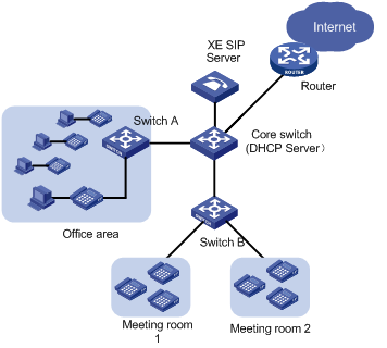
Figure 2-1 Network diagram for voice VLAN configuration
2.1.2 Configuration Outlines
I. Configuration on Switch A
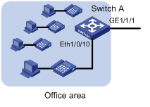
Figure 2-2 Network diagram for Switch A
As the IP phones connected to Switch A get IP addresses automatically, they should send an untagged DHCP request to the DHCP server for an IP address upon their startup. When the DHCP server receives a request, it responds with a temporary IP address, and in addition, the voice VLAN ID, and the IP address of the voice server. After the IP phone receives the response, it discards the temporary IP address and re-sends a DHCP request with the voice VLAN tag to the DHCP server. Thus, the IP phone gets an IP address within the voice VLAN to communicate with the voice server normally.
& Note:
The above procedure describes how a common IP phone gets an IP address. The procedure may differ depending on your IP phone. For the actual procedure of your IP phone, refer to its user manual.
In this network, as Ethernet 1/0/10 of Switch A is required to forward traffic of the default VLAN and the voice VLAN, you should configure Ethernet 1/0/10 as a trunk port or hybrid port. In this example, Ethernet 1/0/10 is configured as a hybrid port. As the traffic from the PCs is untagged, it will be transmitted through the default VLAN. Configure VLAN 100 as the default VLAN and configure the port to transmit the traffic of the default VLAN untagged. As the IP phones send tagged traffic after getting IP addresses within the voice VLAN, configure VLAN 200 as the voice VLAN and configure the voice VLAN to operate in automatic mode on the port. Thus, the port can join/exit the voice VLAN automatically.
& Note:
A hybrid port with voice VLAN enabled in automatic mode joins the voice VLAN in tagged mode automatically and sends the traffic of the voice VLAN tagged.
On Switch A, GigabitEthernet 1/1/1 is uplinked to the core switch to transmit both service traffic and voice traffic. To discriminate data, configure the port as a trunk port to carry VLAN 100 and VLAN 200. As the switch is required to send traffic of the two VLANs tagged, do not configure either of them as the default VLAN.
Figure 2-1 lists the port configurations on Switch A.
Table 2-1 Port configurations on Switch A
|
Port |
Voice VLAN mode |
Port type |
Permitted VLANs and operations on the VLAN traffic |
|
Ethernet 1/0/10 |
Automatic mode |
Trunk/hybrid |
VLAN100: pvid, untagged |
|
GigabitEthernet 1/1/1 |
— |
Trunk |
VLAN100: tagged VLAN200: tagged |
& Note:
The following describes the operations on VLAN traffic:
l pvid: Indicates that the VLAN is configured as the default VLAN of the port.
l untagged: Indicates that the port sends the traffic of the VLAN untagged.
l tagged: Indicates that the port sends the traffic of the VLAN tagged.
For how to configure the default VLAN for a port and configure the port to send traffic untagged/tagged, refer to the accompanied operation manual.
In the following configuration, Ethernet 1/0/10 is configured as a hybrid port.
II. Configuration on Switch B
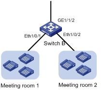
Figure 2-3 Network diagram for Switch B
As two types of IP phones are connected to Switch B, the configuration on Ethernet 1/0/1 is different from that on Ethernet 1/0/2.
l Ethernet 1/0/1
The IP phones connected to Ethernet 1/0/1 are configured with an IP address manually and they send voice traffic untagged. As the port with the voice VLAN mode set to auto does not support receiving untagged voice traffic, you should configure the voice VLAN to operate in manual mode on the port. In addition, configure the voice VLAN as the default VLAN of the port.
l Ethernet 1/0/2
You can configure Ethernet 1/0/2 in a way similar to configuring Ethernet 1/0/10 on Switch A. However, because only IP phones are connected to Ethernet 1/0/2, you can assign the port to the voice VLAN manually to guarantee stable transmission for voice traffic. For the Cisco IP phones connected to the port to communicate with the switch, enable voice VLAN legacy on the port to notify them of the voice VLAN ID, so that the Cisco IP phones can request IP addresses within the voice VLAN. Because the IP phones send tagged voice traffic, you should configure the port to send the traffic of the voice VLAN tagged.
l GigabitEthernet 1/1/2
The port sends the voice traffic received on Switch B. As the meeting rooms should use a voice VLAN different from that for the office area, configure VLAN 400 as the voice VLAN on Switch B and configure the port to send the traffic of VLAN 400 tagged.
Table 2-2 lists the port configurations on Switch B.
Table 2-2 Port configurations on Switch B
|
Port |
Voice VLAN mode |
Port type |
Permitted VLANs and operations on the VLAN traffic |
|
Ethernet 1/0/1 |
Manual mode |
Access/hybrid/trunk |
VLAN400: pvid untagged |
|
Ethernet 1/0/2 |
Manual mode |
Trunk/hybrid |
VLAN400: tagged |
|
GigabitEthernet 1/1/2 |
— |
Trunk/hybrid |
VLAN400: tagged |
In the following configuration, Ethernet 1/0/1 is configured as an access port, and Ethernet 1/0/2 and GigabitEthernet 1/1/2 are configure as trunk ports.
III. Configuration on Core Switch
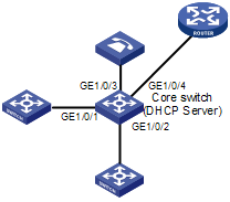
Figure 2-4 Network diagram for the Core Switch
The core switch forwards traffic, allocates IP addresses to IP phones, and specifies the voice VLAN and the voice server address.
According to the configuration on Switch A and Switch B, the core switch is required to forward the traffic of VLAN 100, VLAN 200, and VLAN 400, and allocate IP addresses to IP phones in VLAN 200 and VLAN 400.
As analyzed earlier, when an IP phone is powered up, it first gets an IP address in the default VLAN (VLAN 100) from the DHCP server. The DHCP server should return not only an IP address but also the voice VLAN and the voice server address to the IP phone. To achieve that, you should configure the core switch to use option 184 in the DHCP responses in VLAN 100 for conveying voice related information.
After the IP phone gets the voice VLAN information, it requests for an IP address in the voice VLAN instead of using the IP address obtained in the default VLAN. When receiving the request, the core switch allocates an IP address in VLAN 200 or VLAN 400, whichever the IP phone belongs to. Note that VLAN 200 and VLAN 400 use different IP address segments.
As both the XE voice server and the egress router are connected to the core switch, you should create two VLAN interfaces, and assign GigabitEthernet 1/0/3 and GigabitEthernet 1/0/4 to the two VLANs respectively, thus achieving Layer-3 forwarding.
Table 2-3 lists the interface and port configurations on Switch A.
Table 2-3 Interface and port configurations on the core switch
|
VLAN interface |
IP address and network segment |
Ports involved |
Port type |
Operations on the VLAN traffic |
|
Vlan-interface100 |
192.168.1.1/24 |
GigabitEthernet 1/0/1 |
Trunk |
tagged |
|
Vlan-interface200 |
192.168.2.1/24 |
GigabitEthernet 1/0/1 |
Trunk |
tagged |
|
Vlan-interface400 |
192.168.4.1/24 |
GigabitEthernet 1/0/2 |
Trunk |
tagged |
|
Vlan-interface300 |
192.168.3.1/24 |
GigabitEthernet 1/0/3 |
Access |
untagged |
|
Vlan-interface500 |
192.168.5.1/24 |
GigabitEthernet 1/0/4 |
Access |
untagged |
2.1.3 Configuration Procedure
I. Devices and software version used
Switch A and Switch B are the S3600 series whose software version is Release 1510. The core switch is a S5600 series Ethernet switch whose software version is Release 1510.
II. Configuration steps
l Configuration on Switch A
# Create VLAN 100 and VLAN 200.
<SwitchA> system-view
[SwitchA] vlan 100
[SwitchA-vlan100] quit
[SwitchA] vlan 200
[SwitchA-vlan200] quit
# Assign GigabitEthernet 1/1/1 and Ethernet 1/1/10 to the specified VLANs according to Table 2-1.
[SwitchA] interface GigabitEthernet 1/1/1
[SwitchA-GigabitEthernet1/1/1] port link-type trunk
[SwitchA-GigabitEthernet1/1/1] port trunk permit vlan 100 200
[SwitchA-GigabitEthernet1/1/1] quit
[SwitchA] interface Ethernet 1/0/10
[SwitchA-Ethernet1/0/10] port link-type hybrid
[SwitchA-Ethernet1/0/10] port hybrid vlan 100 untagged
[SwitchA-Ethernet1/0/10] port hybrid pvid vlan 100
[SwitchA-Ethernet1/0/10] quit
# Enable voice VLAN on Ethernet 1/0/10.
[SwitchA-Ethernet1/0/10] voice vlan enable
# Set the voice VLAN aging time to 100 minutes.
[SwitchA-Ethernet1/0/10] quit
[SwitchA] voice vlan aging 100
# Enable voice VLAN security mode so that only voice traffic is transmitted in the voice VLAN. (Optional. The voice VLAN security mode is enabled by default.)
[SwitchA] voice vlan security enable
# Configure VLAN 200 as the voice VLAN globally.
[SwitchA] voice vlan 200 enable
l Configuration on Switch B
# Create VLAN 100 and VLAN 400.
<SwitchB> system-view
[SwitchB] vlan 100
[SwitchB-vlan100] quit
[SwitchB] vlan 400
[SwitchB-vlan400] quit
# Assign Ethernet 1/0/1, Ethernet 1/0/2, and GigabitEthernet 1/1/2 to the specified VLANs according to Table 2-2.
[SwitchB] interface Ethernet 1/0/1
[SwitchB-Ethernet1/0/1] port access vlan 400
[SwitchB-Ethernet1/0/1] quit
[SwitchB] interface Ethernet 1/0/2
[SwitchB-Ethernet1/0/2] port link-type trunk
[SwitchB-Ethernet1/0/2] port trunk permit vlan 100 400
[SwitchB-Ethernet1/0/2] quit
[SwitchB] interface GigabitEthernet1/1/2
[SwitchB-GigabitEthernet1/1/2] port link-type trunk
[SwitchB-GigabitEthernet1/1/2] port trunk permit vlan 100 400
[SwitchB-GigabitEthernet1/1/2] quit
# Enable voice VLAN legacy on Ethernet 1/0/2.
[SwitchB] interface Ethernet 1/0/2
[SwitchB-Ethernet1/0/2] voice vlan legacy
[SwitchB-Ethernet1/0/2] quit
# Configure the voice VLAN to operate in manual mode on Ethernet 1/0/1 and Ethernet 1/0/2, and enable voice VLAN on the two ports.
[SwitchB] interface Ethernet 1/0/1
[SwitchB-Ethernet1/0/1] undo voice vlan mode auto
[SwitchB-Ethernet1/0/1] voice vlan enable
[SwitchB-Ethernet1/0/1] quit
[SwitchB] interface Ethernet 1/0/2
[SwitchB-Ethernet1/0/2] undo voice vlan mode auto
[SwitchB-Ethernet1/0/2] voice vlan enable
[SwitchB-Ethernet1/0/2] quit
# Add an OUI address 00e3-f200-0000 with the description of Meeting room1 globally.
[SwitchB] voice vlan mac-address 00e3-f200-0000 mask ffff-ff00-0000 description Meeting room1
# Enable voice VLAN security mode so that only voice traffic is transmitted in the voice VLAN. This step is optional. The voice VLAN security mode is enabled by default.
[SwitchB] voice vlan security enable
# Configure VLAN 400 as the voice VLAN globally.
[SwitchB] voice vlan 400 enable
l Configure the core switch
# Create VLAN 100, VLAN 200, VLAN 300, VLAN 400, and VLAN 500 on the core switch. Assign the specified ports to their respective VLANs according to Table 2-3. The configuration procedure is omitted here.
# Create VLAN interfaces and assign IP addresses to the VLAN interfaces according to Table 2-3. The configuration procedure is omitted here.
# Enable DHCP globally.
<CoreSwitch> system-view
[CoreSwitch] dhcp enable
# Create a global address pool vlan100 to allocate IP addresses on the network segment 192.168.1.1/24 to devices in the default VLAN (VLAN 100).
[CoreSwitch] dhcp server ip-pool vlan100
[CoreSwitch-dhcp-pool-vlan100] network 192.168.1.0 mask 255.255.255.0
# Configure VLAN 200 as the voice VLAN and the voice server IP address as 192.168.3.3 for option 184 in the address pool vlan100.
[CoreSwitch-dhcp-pool-vlan100] voice-config ncp-ip 192.168.3.3
[CoreSwitch-dhcp-pool-vlan100] voice-config voice-vlan 200 enable
[CoreSwitch-dhcp-pool-vlan100] quit
# Configure VLAN-interface 100 to operate in global address pool mode.
[CoreSwitch] interface Vlan-interface 100
[CoreSwitch-Vlan-interface100] dhcp select global
[CoreSwitch-Vlan-interface100] quit
# Create an address pool for VLAN-interface 200 and VLAN-interface 400 respectively to allocate IP addresses for the IP phones in the office area and the IP phone in meeting room 2.
[CoreSwitch] interface Vlan-interface 200
[CoreSwitch-Vlan-interface200] dhcp select interface
[CoreSwitch-Vlan-interface200] quit
[CoreSwitch] interface Vlan-interface 400
[CoreSwitch-Vlan-interface400] dhcp select interface
& Note:
For detailed information about DHCP configuration, refer to the user manual of the S3600 series.
The core switch thus configured should be able to allocate IP addresses, voice VLANs, and the voice server IP address for IP phones in VLAN 200 and VLAN 400, and to forward voice traffic at Layer 3. If required, configure dynamic routing protocols on the core switch, which is beyond the scope of this document.
III. Configuration remarks
After you finish the configuration, the IP phones in each area can establish connections with the voice server, get telephone numbers, and communicate normally. For the configuration on the voice server, refer to the user manual of the H3C XE voice server.
You are recommended to enable DHCP snooping and some security functions on Switch A and Switch B to ensure that only legal IP phones that get IP addresses from the core switch can use the service, thus preventing malicious interception.