- Table of Contents
-
- H3C Low-End Ethernet Switches Configuration Examples(V1.04)
- 01-DHCP Configuration Examples
- 02-QACL Configuration Examples
- 03-802.1x Configuration Examples
- 04-SSH Configuration Examples
- 05-Routing Configuration Examples
- 06-Multicast Protocol Configuration Examples
- 07-VLAN Configuration Examples
- 08-Voice VLAN configuration examples
- 09-QinQ Configuration Examples
- 10-ARP Attack Prevention Configuration Examples
- Related Documents
-
| Title | Size | Download |
|---|---|---|
| 07-VLAN Configuration Examples | 303.96 KB |
Table of Contents
1.1.1 Support for VLAN on H3C Low-End Ethernet Switches
1.2.1 Configuring Basic VLAN Settings
1.2.2 Configuring Basic Settings of a VLAN Interface
1.2.3 Protocol VLAN Configuration
Chapter 2 Configuration Examples
2.1 VLAN Configuration Example
VLAN Configuration Examples
Keywords: VLAN, 802.1q, VLAN interface, protocol VLAN
Abstract: This document introduces how VLAN of the H3C series Ethernet switches is applied and configured in practical networking implementations and how protocols are used in conjunction with VLANs.
Acronyms: VLAN (Virtual local area network)
Chapter 1 VLAN Overview
1.1 VLAN Support Matrix
1.1.1 Support for VLAN on H3C Low-End Ethernet Switches
Table 1-1 Support for VLAN on H3C low-end ethernet switches
|
Feature (right) |
802.1Q VLAN |
VLAN interface |
Protocol VLAN |
|
Model (below) |
|||
|
l |
l |
l |
|
|
S3600-SI |
l |
l |
l |
|
S5600 |
l |
l |
l |
|
S5100-EI |
l |
¡ |
l |
|
S3100-SI |
l |
¡ |
– |
|
S3100-52P |
l |
l |
– |
& Note:
l In the above table, the solid dots (l) indicate that the corresponding models provide full support for the function; the hollow dots (¡) indicate that the corresponding models provide incomplete support for the function, that is, the corresponding models support only the VLAN-interface for the management VLAN; the dashes (–) indicate that the corresponding models do not support the function.
l For detailed information about the support of your device for VLAN, refer to the user manual for your device.
1.2 Configuration Guide
& Note:
l The configuration procedure differs by device. In this guide, the S3600 series are taken as an example. For how to configure VLAN on other models, refer to their accompanied operation manuals.
l The configuration example in this guide provides only basic configuration procedures. For detailed information about the involved functions, refer to the corresponding operation manual and command manual.
1.2.1 Configuring Basic VLAN Settings
The H3C series switches support IEEE 802.1Q VLAN. The technology allows you to organize Ethernet ports into virtual workgroups by assigning them to different VLANs.
Follow these steps to create a VLAN and perform basic VLAN configuration:
|
To do... |
Use the command... |
Remarks |
|
Enter system view |
system-view |
— |
|
Create multiple VLANs in bulk |
vlan { vlan-id1 to vlan-id2 | all } |
Optional |
|
Create a VLAN and enter VLAN view |
vlan vlan-id |
Required By default, only one default VLAN (VLAN 1) exists in the system. |
|
Assign a name for the current VLAN |
name text |
Optional By default, the name of a VLAN is its VLAN ID, for example, VLAN 0001. |
|
Configure the description of the current VLAN |
description text |
Optional By default, the description of a VLAN is its VLAN ID, for example, VLAN 0001. |
|
Display VLAN information |
display vlan [ vlan-id [ to vlan-id ] | all | dynamic | static ] |
Available in any view |
You can assign a port to a VLAN in Ethernet port view or in VLAN view.
Follow these steps to assign a port to a VLAN in VLAN view:
|
To do... |
Use the command... |
Remarks |
|
Enter system view |
system-view |
— |
|
Enter VLAN view |
vlan vlan-id |
— |
|
Assign a list of Ethernet ports to the VLAN |
port interface-list |
Required By default, all ports belong to the default VLAN (VLAN 1). |
& Note:
Only access ports can be assigned to a VLAN in VLAN view. You can assign trunk or hybrid ports to a VLAN only in Ethernet port view.
Follow these steps to assign a port to a VLAN in Ethernet port view:
|
To do... |
Use the command... |
Remarks |
|
|
Enter system view |
system-view |
— |
|
|
Enter Ethernet port view |
interface interface-type interface-number |
— |
|
|
Configure the port type |
port link-type { access | trunk | hybrid } |
Optional By defaults, all ports are access ports. |
|
|
Assign the current port to the specified VLAN(s) |
For an access port |
port access vlan vlan-id |
Required By default, all the three types of ports belong to the default VLAN (VLAN 1). |
|
For a trunk port |
port trunk permit vlan { vlan-id-list | all } |
||
|
For a hybrid port |
port hybrid vlan vlan-id-list { tagged | untagged } |
||
|
Specify the default VLAN for the current port |
For a trunk port |
port trunk pvid vlan vlan-id |
Optional By default, the default VLAN of an Ethernet port is VLAN 1. Because an access port can be assigned to only one VLAN, its default VLAN is the VLAN to which it belongs. Therefore, you do not need to configure a default VLAN for it. |
|
For a hybrid port |
port hybrid pvid vlan vlan-id |
||
1.2.2 Configuring Basic Settings of a VLAN Interface
You can enable your switch to perform Layer 3 forwarding by configuring VLAN interfaces with IP addresses on the switch.
Follow these steps to configure basic settings of a VLAN interface:
|
To do... |
Use the command... |
Remarks |
|
Enter system view |
system-view |
— |
|
Create a VLAN interface and enter VLAN interface view |
interface Vlan-interface vlan-id |
Required By default, no VLAN interface exists. |
|
Assign an IP address to the current VLAN interface |
ip address ip-address { mask | mask-length } [ sub ] |
Required No IP address is assigned to any VLAN interface by default. |
|
Configure the description of the current VLAN interface |
description text |
Optional By default, the description of a VLAN interface is its name, for example, Vlan-interface1 Interface. |
|
Shut down the VLAN interface |
shutdown |
Optional By default, a VLAN interface is in the up state. In this case, the VLAN interface is up so long as one port in the VLAN is up and goes down if all ports in the VLAN go down. An administratively shut down VLAN interface however will be in the down state until you bring it up, regardless of how the state of the ports in the VLAN changes. |
|
Bring up the VLAN interface |
undo shutdown |
|
|
Display information about the VLAN interface |
display interface Vlan-interface [ vlan-id ] |
Available in any view |
& Note:
l Before creating a VLAN interface for a VLAN, create the VLAN first.
l On some H3C series switches, only one VLAN interface is supported, and you must configure its VLAN as the default VLAN with the management-vlan command before creating the VLAN interface. For detailed configurations, refer to the corresponding user manual.
1.2.3 Protocol VLAN Configuration
Protocol VLAN enables your switch to assign an incoming untagged frame to a VLAN based on its protocol. To configure a protocol VLAN, first create a protocol template to enable protocol VLAN, and then assign Ethernet ports to the protocol VLAN.
Follow these steps to configure a protocol VLAN:
|
To do... |
Use the command... |
Remarks |
|
Enter system view |
system-view |
— |
|
Enter VLAN view |
vlan vlan-id |
— |
|
Create a protocol template |
protocol-vlan [ protocol-index ] { at | ip | ipx { ethernetii | llc | raw | snap } | mode { ethernetii etype etype-id | llc { dsap dsap-id ssap ssap-id } | snap etype etype-id } } |
Required No protocol template exists by default. |
|
Return to system view |
quit |
— |
|
Enter Ethernet port view |
interface interface-type interface-number |
— |
|
Configure the port as a hybrid port |
port link-type hybrid |
Required All Ethernet ports are access ports by default. |
|
Assign the port to the protocol VLAN and configure the port to forward the frames of the VLAN with their VLAN tag removed |
port hybrid vlan vlan-id untagged |
Required All ports belong to VLAN 1 by default. |
|
Associate the port with the protocol VLAN |
port hybrid protocol-vlan vlan vlan-id { protocol-index [ to protocol-index-end ] | all } |
Required By default, an Ethernet port is not associated with any protocol VLAN. |
|
Display information about the protocol templates of the specified VLAN(s) |
display protocol-vlan vlan { vlan-id [ to vlan-id ] | all } |
Available in any view |
|
Display information about the protocol templates of the protocol VLANs associated with the specified port(s) |
display protocol-vlan interface { interface-type interface-number [ to interface-type interface-number ] | all } |
Chapter 2 Configuration Examples
2.1 VLAN Configuration Example
2.1.1 Network Requirements
A company has three departments: the R&D department, the marketing department, and the design department. The three departments are located in the same building. The R&D department and the marketing department are located in different office areas. The design department and part of the R&D department share the same office area. The hosts of the design department use the Apple operating system (OS), and the hosts of the other two departments use Windows. Use VLANs to fulfill the following:
l Employees of the same department can communicate with each other, while employees of different departments cannot.
l The R&D department and the marketing department are on different IP network segments. A switch (Core-Switch A in Figure 2-1) assigns addresses to hosts of the two departments automatically.
l Both the R&D department and the marketing department can access the public servers. However, the design server and the R&D server are accessible to only the employees of the design department and the R&D department respectively.
l The hosts and server of the R&D department and those of the design department cannot access the Internet; the hosts and server of the marketing department and those of the design department cannot access the VPN of the R&D department.
2.1.2 Network Diagram
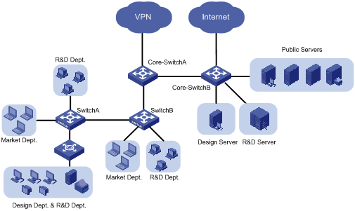
Figure 2-1 Network diagram for VLAN configuration
2.1.3 Configuration Outlines
I. Configuration on Switch A
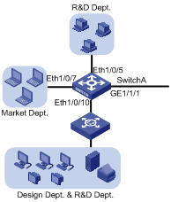
Figure 2-2 Network diagram for Switch A
On Switch A, assign the port connecting to the independent office area of the R&D department and the port connecting to the independent office area of the marketing department to different VLANs, thus isolating the two areas.
As the shared office area is used by two departments, assigning the port connecting to the area to a VLAN cannot isolate the two departments. Considering that the design department and the R&D department use different operating systems, you can assign Apple hosts whose network protocol is Appletalk and Windows hosts whose network protocol is IP to different protocol VLANs.
Configure GigabitEthernet 1/1/1 to permit frames of all existing VLANs to pass through with VLAN tags for VLAN identification.
II. Configuration on Switch B
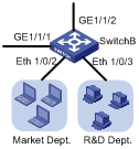
Figure 2-3 Network diagram for Switch B
On Switch B, assign the port connecting to the marketing department and the port connecting to the R&D department to different VLANs. Note that, the configuration of the VLAN to which a department belongs must be the same on both Switch A and Switch B. Configure the port connecting to Core-Switch A to permit the frames of all existing VLANs to pass through with VLAN tags.
III. Configuration on Core-Switch A
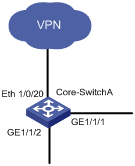
Figure 2-4 Network diagram for Core-Switch A
On Core-Switch A, configure the port connecting to Switch B to permit the frames of the three departments to pass through.
Configure Core-Switch A as the DHCP server for IP address assignment. As it is the egress device for the R&D department to access the VPN, configure Core-Switch A as the gateway for the R&D department and configure the port connecting to the VPN to permit only the frames of the R&D department to pass through. As Core-Switch B is the egress device for accessing the Internet and only the marketing department is allowed to access the Internet, configure Core-Switch B as the gateway for the marketing department.
IV. Configuration on Core-Switch B
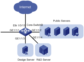
Figure 2-5 Network diagram for Core-Switch B
Each server is connected to Core-Switch B through an individual port. Assign these ports to different VLANs to provide the departments exclusive access to their respective servers.
As the public servers are accessible to both the R&D department and the marketing department, create an individual VLAN for the public servers to forward Layer 3 traffic between the servers and the clients. As Core-Switch A forwards Layer 3 traffic between the R&D department and the public servers, configure the link between Core-Switch B and Core-Switch A to permit the frames of the VLAN created for the public servers to pass through besides the frames of the three departments.
As Core-Switch B is the egress device for accessing the Internet and only the marketing department is allowed to access the Internet, configure a VLAN interface with an IP address for the VLAN of the marketing department and configure the port connecting to the Internet to permit only the frames of the VLAN to pass through. The IP address of the VLAN interface will be used as the gateway address for the marketing department on Core-Switch A.
V. Summary
Assign the hosts and server of the R&D department, those of the marketing department, and those of the design department to VLAN 100, VLAN 200, and VLAN 300 respectively. The public servers belong to VLAN 500 and lie on the network segment 192.168.50.0. The following diagram shows the planned VLANs:
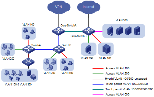
Figure 2-6 Network diagram for the deployment of VLANs
2.1.4 Configuration Procedure
I. Device and version used
S3600 series, Test 1510.
II. Configuration procedure
l Configure Switch A
# Create VLAN 100, VLAN 200, and VLAN 300.
<SwitchA> system-view
[SwitchA] vlan 100
[SwitchA-vlan100] quit
[SwitchA] vlan 200
[SwitchA-vlan200] quit
[SwitchA] vlan 300
[SwitchA-vlan300]
[SwitchA-vlan300] quit
# Assign Ethernet 1/0/5 to VLAN 100.
[SwitchA] interface Ethernet 1/0/5
[SwitchA-Ethernet1/0/5] port access vlan 100
[SwitchA-Ethernet1/0/5] quit
# Assign Ethernet 1/0/7 to VLAN 200.
[SwitchA] interface Ethernet 1/0/7
[SwitchA-Ethernet1/0/7] port access vlan 200
[SwitchA-Ethernet1/0/7] quit
# Create a protocol template for VLAN 100 to carry IP and a protocol template for VLAN 300 to carry Appletalk.
[SwtichA] vlan 100
[SwitchA-vlan100] protocol-vlan ip
[SwitchA-vlan100] quit
[SwitchA] vlan 300
[SwitchA-vlan300] protocol-vlan at
[SwitchA-vlan300] quit
# Create a user-defined protocol template for VLAN 100 to carry ARP for IP communication, assuming that Ethernet_II encapsulation is used.
[SwitchA] vlan 100
[SwitchA-vlan100] protocol-vlan mode ethernetii etype 0806
# Configure Ethernet 1/0/10 as a hybrid port permitting the frames of VLAN 100 and VLAN 300 to pass through untagged.
[SwitchA] interface Ethernet 1/0/10
[SwitchA-Ethernet1/0/10] port link hybrid
[SwitchA-Ethernet1/0/10] port hybrid vlan 100 300 untagged
# Associate Ethernet 1/0/10 with all the protocol templates of VLAN 100 and VLAN 300.
[SwitchA-Ethernet1/0/10] port hybrid protocol-vlan vlan 100 all
[SwitchA-Ethernet1/0/10] port hybrid protocol-vlan vlan 300 all
[SwitchA-Ethernet1/0/10] quit
# Configure GigabitEthernet 1/1/1 as a trunk port permitting the frames of VLAN 100, VLAN 200, and VLAN 300 to pass through with VLAN tags.
[SwitchA] interface GigabitEthernet 1/1/1
[SwitchA-GigabitEthernet1/1/1] port link-type trunk
[SwitchA-GigabitEthernet1/1/1] port trunk permit vlan 100 200 300
l Configure Switch B
# Create VLAN 100, VLAN 200, and VLAN 300 on Switch B as you have done on Switch A.
# Assign Ethernet 1/0/2 and Ethernet 1/0/3 to VLAN 200 and VLAN 100 respectively.
<SwitchB> system-view
[SwitchB] interface Ethernet 1/0/2
[SwitchB-Ethernet1/0/2] port access vlan 200
[SwitchB-Ethernet1/0/2] quit
[SwitchB] interface Ethernet 1/0/3
[SwitchB-Ethernet1/0/3] port access vlan 100
[SwitchB-Ethernet1/0/3] quit
# Configure GigabitEthernet 1/1/1 and GigabitEthernet 1/1/2 as trunk ports permitting the frames of VLAN 100, VLAN 200, and VLAN 300 to pass through with VLAN tags.
[SwitchB] interface GigabitEthernet 1/1/1
[SwitchB-GigabitEthernet1/1/1] port link-type trunk
[SwitchB-GigabitEthernet1/1/1] port trunk permit vlan 100 200 300
[SwitchB-GigabitEthernet1/1/1] quit
[SwitchB] interface GigabitEthernet 1/1/2
[SwitchB-GigabitEthernet1/1/2] port link-type trunk
[SwitchB-GigabitEthernet1/1/2] port trunk permit vlan 100 200 300
[SwitchB-GigabitEthernet1/1/2] quit
l Configure Core-Switch A
# Create VLAN 100, VLAN 200, and VLAN 300 on Core-Switch A. The configuration procedure is the same as that on Switch A.
# Configure GigabitEthernet 1/1/1 and GigabitEthernet 1/1/2 as trunk ports permitting the frames of VLAN 100, VLAN 200, and VLAN 300 to pass through with VLAN tags. The configuration procedure is the same as that on Switch B.
# Create VLAN-interface 100 and assign it IP address 192.168.30.1. Use this address as the IP address of the gateway for the R&D department. Allocate IP addresses in the address pool 192.168.30.0/24 for the hosts of the R&D department.
[Core-SwitchA] dhcp enable
[Core-SwitchA] interface Vlan-interface 100
[Core-SwitchA-Vlan-interface100] ip address 192.168.30.1 24
[Core-SwitchA-Vlan-interface100] dhcp select interface
[Core-SwitchA-Vlan-interface100] quit
# Create a global IP address pool mk with the address segment 192.168.40.0/24 to allocate IP addresses for the hosts of the marketing department. Configure the gateway IP address as 192.168.40.1 for the hosts, pointing to Core-Switch B.
[Core-SwitchA] dhcp server ip-pool mk
[Core-SwitchA-dhcp-pool-mk] network 192.168.40.0 mask 255.255.255.0
[Core-SwitchA-dhcp-pool-mk] gateway-list 192.168.40.1
& Note:
For detailed information about DHCP configuration, refer to the user manual of the S3600 series.
# Create VLAN 500 and VLAN-interface 500 on Core-Switch A and assign IP address 192.168.50.1/24 to VLAN-interface 500. Configure the trunk port GigabitEthernet 1/1/1 to carry VLAN 500 and configure GigabitEthernet 1/1/1 to permit the frames of VLAN 500 to pass through with VLAN tags.
[Core-SwitchA] vlan 500
[Core-SwitchA-vlan500] quit
[Core-SwitchA] interface Vlan-interface 500
[Core-SwitchA-Vlan-interface500] ip address 192.168.50.1 24
[Core-SwitchA-Vlan-interface500] quit
[Core-SwitchA] interface GigabitEthernet 1/1/1
[Core-SwitchA-GigabitEthernet1/1/1] port trunk permit vlan 500
# Create a VLAN-interface on Core-Switch A to forward traffic of the R&D department to the VPN and assign an IP address to the VLAN-interface. Assign Ethernet 1/0/20 to the VLAN corresponding to the VLAN-interface. The configuration procedure is omitted here.
l Configuration on Core-Switch B
# Create VLAN 100, VLAN 200, VLAN 300, and VLAN 500 on Core-Switch B. The configuration procedure is the same as that on Switch A.
# Configure GigabitEthernet 1/1/1 as a trunk port permitting the frames of VLAN 100, VLAN 200, VLAN 300, and VLAN 500 to pass through with VLAN tags. The configuration procedure is omitted here.
# Create a VLAN-interface on Core-Switch B to forward traffic of the marketing department to the Internet and assign an IP address to the VLAN-interface. Assign Ethernet 1/0/15 to the VLAN corresponding to the VLAN-interface. The configuration procedure is omitted here.
# Configure GigabitEthernet 1/1/3 and GigabitEthernet 1/1/4 to permit only the frames of VLAN 300 and only the frames of VLAN 100 to pass through respectively.
# Configure GigabitEthernet 1/1/2 to permit only the frames of VLAN 500 to pass through.
# Assign IP address 192.168.40.1 to VLAN-interface 200. The configuration procedure is omitted here.
III. Configuration remarks
After you finish the configuration, the hosts of the three departments should be isolated at the data link layer.
As no VLAN interface is created for the VLAN of the marketing department on the VPN gateway Core-Switch A, the hosts of the marketing department should not be able to access the VPN or the R&D department through Layer 3 forwarding. Similarly, as no VLAN interface is created for the VLAN of the R&D department on the Internet gateway Core-Switch B, the hosts of the R&D department should not be able to access the Internet or the marketing department through Layer 3 forwarding.
Thus, all departments are isolated at both the data link layer and the network layer.
& Note:
To prevent users from modifying the IP addresses and gateways of hosts for accessing unauthorized network resources, you are recommended to enable DHCP-Snooping on Switch A and Switch B to monitor the IP addresses of clients. For detailed information about DHCP-Snooping configuration, refer to the user manual of the S3600 series.
2.2 Precautions
l Because IP depends on ARP for address resolution in Ethernet, you are recommended to configure the IP and ARP templates in the same VLAN and associate them with the same port to prevent communication failure.
l The maximum number of protocol templates that can be bound to a port varies by device.