- Table of Contents
-
- H3C S9500 Series Routing Switches Installation Manual-(V1.24)
- 00-1Cover
- 01-Chapter 1 Product Overview
- 02-Chapter 2 Installation Preparations
- 03-Chapter 3 Switch Installation
- 04-Chapter 4 System Commissioning
- 05-Chapter 5 Switch Monitoring and Maintenance
- 06-Appendix A Cable Management
- 07-Appendix B Engineering Labels for Cables
- 08-Appendix C Installation of Lightning Arrester for AC Power
- Related Documents
-
| Title | Size | Download |
|---|---|---|
| 04-Chapter 4 System Commissioning | 729 KB |
Table of Contents
Chapter 4 System Commissioning
4.1 Setting Up Configuration Environment
4.1.1 Setting Up Configuration Environment
4.1.2 Setting Terminal Parameters
4.2.1 Checklist for Switch Power-On
4.2.3 Verifying after Power-on (Recommended)
Chapter 4 System Commissioning
4.1 Setting Up Configuration Environment
4.1.1 Setting Up Configuration Environment
Connect a terminal (a PC in this example) to the switch with the console cable.

Figure 4-1 Connect a PC to the switch with a Console cable
4.1.2 Setting Terminal Parameters
This section describes how to set the terminal parameters.
1) Start the PC, and run the terminal emulation program. The following uses a PC running Windows XP HyperTerminal as an example.
2)
Select Start > Programs > Accessories
> Communications > HyperTerminal to access the HyperTerminal
window. Click ![]() in the window to set up a new connection. The
Connection Description dialog box appears, as shown in Figure 4-2. .
in the window to set up a new connection. The
Connection Description dialog box appears, as shown in Figure 4-2. .
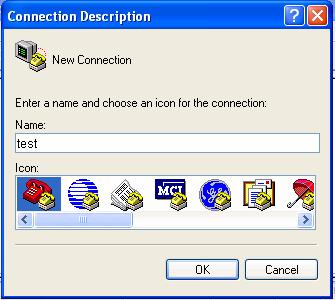
Figure 4-2 Connection Description interface of HyperTerminal
3) Enter the name of the new connection in the Connection Description dialog box, and click OK. The system displays the interface shown in Figure 4-3. Select a port in the Connect using drop-down list.
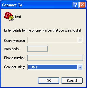
Figure 4-3 Select a port for the HyperTerminal connection
4) Set serial port parameters. Set the bits per second to 9600, data bits to 8, parity to none, stop bits to 1, and flow control to none.
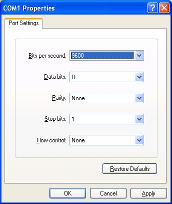
Figure 4-4 Set serial port parameters
5) Click OK after setting the serial port parameters to enter the HypterTerminal window, as shown in Figure 4-5.
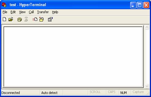
Figure 4-5 HyperTerminal window
6) Select Properties in the HyperTerminal window to access the Properties window. Click Settings in the Window (as shown in Figure 4-6), select VT100 for terminal emulation, and click OK.
& Note:
You are recommended to select the Windows keys option button.
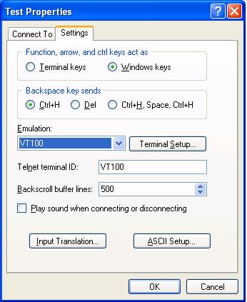
Figure 4-6 Set the terminal emulation parameters
4.2 Powering On the Switch
4.2.1 Checklist for Switch Power-On
Before powering on the switch, make sure that:
l The interface cables, power cables and the grounding cable are correctly connected.
l The power outlet voltage is the same as the one indicated on the switch label.
l The console cable is correctly connected, the console terminal or PC is powered on, and the terminal parameters are properly configured.
![]() Caution:
Caution:
Before powering on the switch, learn where the power switch is located so that you can disconnect the power supply in time in case of an emergency..
4.2.2 Powering on the Switch
To power on the switch, follow the procedure below:
l Turn on the power switch of the power source providing power to the switch.
l Turn on the power switch of the PWR on the switch.
4.2.3 Verifying after Power-on (Recommended)
To ensure the configuration works that you will make on the switch, you are recommended to check the switch after powering it on to make sure that:
l The cooling system is working. In this case, you can hear the noise caused by fan rotation and feel that there is air exhausted out.
l All the system LEDs on the SRPUs function normally.
4.2.4 Boot Interface
The S9505 switch is used as an example in this section.
The following is the information that will be output at the console terminal when you power on the switch.
ZBB_TEST
Starting...
*************************************************
* *
* H3C S9500 Bootrom, Version 206 *
* *
*************************************************
Copyright (c) 2004-2007 H3C Technologies Co., Ltd. All rights reserved.
CPU type : MPC755
CPU L2 Cache : 1024KB
CPU Clock Speed : 400MHz
BUS Clock Speed : 100MHz
Memory Size : 512MB
Board self testing...........................
The board is steady
SlotNo of this board is 6
The MCX is existent
BootRom main system CRC check is OK
82559 register testing is OK
EPLD1 testing is OK
EPLD2 testing is OK
16c2552 register testing is OK
Please check LEDs......................LED testing finished
The switch's Mac address is 000f.e222.ce4d
Press Ctrl+B to enter Boot Menu... 0
Auto-booting...
Boot from primary file
Boot from cf:/s9500v100r006b01d002sp01_full.app
Initialize CF card...done
Loading from CF card...done
Decompress Image................................................................
................................................................................
................................................................................
...............................OK!
Starting at 0x10000...
Be sure the BaudRate is 9600bps!
User interface con0 is available.
Press ENTER to get started.
The above prompt information appears when the switch completes its boot sequence. Press <Enter> to begin configuring the switch at the prompt “<H3C>”.
The S9500 series provide abundant command views. For more information about the configuration commands and the Command Line Interface (CLI), see H3C S9500 Series Routing Switches Operation Manual.